鹰眼摄像头(OV7725)的使用
原载:http://blog.csdn.net/lxk7280/article/details/26975233?utm_source=tuicool
凭借着OV7620,将已经调好速度控制和角度控制的车子能跑起来了。基础功能实现后就开始对车子优化了。
一个好的人眼睛最重要,同样对于一个好的平衡车,摄像头传感器最重要。因此我决心首先做的是对摄像头的优化。
方针:
OV7620 --> OV7725(鹰眼摄像头) 使用:KEIL 鹰眼摄像头 超核库
OV7620的缺点:
OV7620是1/3”CMOS彩色/黑白图像传感器。它支持连续和隔行两种 扫描方式,VGA与QVGA两种图像格式;最高像素为664×492, 帧速率为30fps。而他的缺点正是在此,帧速率太低。每秒中只能产生30唱图像。可以确定他的
VSYNC信号为30HZ。
帧速率不高为何是缺点:
因为车子跑到一定速度之后,图像变化很快,帧的速率低导致了道路实时性差,不能够及时刷新道路情况。所以会影响智能车的提速。
鹰眼摄像头(OV7725)的优点:
1.高达150HZ的帧频率。
2.硬件二值化。(也有人认为是缺点。)
3.BGA封装:
但是鹰眼的制造商野火,采用捆绑销售,每次买的时候必须购买套装。不过商家也是为了购买者着想,因为很多人不会自己驱动OV7725,只会对例程进行修改,不会移植,这样的购买者买套件确实也不失为一个好方法。
不过博主比较穷,在一番软磨之下,商家给我单卖了一个鹰眼摄像头(OV7725),在此谢谢商家了。
驱动鹰眼的步骤:
1.知道该款摄像头的工作特点和方式。
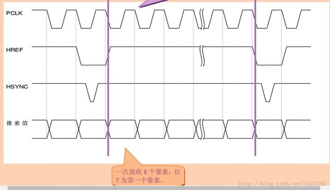
第一大步:理解时序图。
2.在我介绍OV7620的使用(http://blog.csdn.net/lxk7280/article/details/22207001)的时候,就说了理解时序图是驱动一款摄像头的重中之重。尤其是对于鹰眼这款比较特殊的摄像头。
接下来一个必须理解的地方,否则就驱动不了该款摄像头。
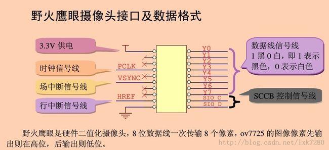
那就是:鹰眼摄像头的一个PCLK信号传来的时候,会传输8个像素点。而不是OV7620的一个PCLK信号,对应1个像素点。
So:如果一行为80个点,那么一个行信号中只会有10个PCLK信号,而不是80个PCLK信号。
示例:采集到:0xFF 0X00 。 对应二值化的像素点。 黑黑黑黑白白白白
为了更好的让自己理解鹰眼摄像头的时序图,我在实验室的示波器上仔细看了下各个信号的波形。如下图:
场信号和行信号波形:
看完这么多关于时序图的波形后,相信大家对鹰眼摄像头的波形都了解了。
接下来开始进攻第二大部分:SCCB的操作。
3. 没有对SCCB进行操作,就没办法操作摄像头。
然后,撰写关于鹰眼摄像头的函数:
接下来就能成功的在上位机上看到相应的图像了。
有人会奇怪为什么使用OV系列的摄像头每次都要进行SCCB的操作呢?难道它自己不会保存上次的操作结果吗?
原因是:OV系列的摄像头的寄存器是EEPROM,不稳定,数据很容易丢失,因此程序每次初始化时我们都要重新写入寄存器设置。
需要修改的寄存器有,PCLK速率,帧率、图像亮度、对比度、色饱和度、镜像等功能。
步骤:
首先给出OV7725的SCCB各个功能对应的寄存器的写入值:
- #ifndef _OV7725_REG_H_
- #define _OV7725_REG_H_
- #define OV7725_ID 0x21
- #define OV7725_GAIN 0x00
- #define OV7725_BLUE 0x01
- #define OV7725_RED 0x02
- #define OV7725_GREEN 0x03
- #define OV7725_BAVG 0x05
- #define OV7725_GAVG 0x06
- #define OV7725_RAVG 0x07
- #define OV7725_AECH 0x08
- #define OV7725_COM2 0x09
- #define OV7725_PID 0x0A
- #define OV7725_VER 0x0B
- #define OV7725_COM3 0x0C
- #define OV7725_COM4 0x0D
- #define OV7725_COM5 0x0E
- #define OV7725_COM6 0x0F
- #define OV7725_AEC 0x10
- #define OV7725_CLKRC 0x11
- #define OV7725_COM7 0x12
- #define OV7725_COM8 0x13
- #define OV7725_COM9 0x14
- #define OV7725_COM10 0x15
- #define OV7725_REG16 0x16
- #define OV7725_HSTART 0x17
- #define OV7725_HSIZE 0x18
- #define OV7725_VSTRT 0x19
- #define OV7725_VSIZE 0x1A
- #define OV7725_PSHFT 0x1B
- #define OV7725_MIDH 0x1C
- #define OV7725_MIDL 0x1D
- #define OV7725_LAEC 0x1F
- #define OV7725_COM11 0x20
- #define OV7725_BDBase 0x22
- #define OV7725_BDMStep 0x23
- #define OV7725_AEW 0x24
- #define OV7725_AEB 0x25
- #define OV7725_VPT 0x26
- #define OV7725_REG28 0x28
- #define OV7725_HOutSize 0x29
- #define OV7725_EXHCH 0x2A
- #define OV7725_EXHCL 0x2B
- #define OV7725_VOutSize 0x2C
- #define OV7725_ADVFL 0x2D
- #define OV7725_ADVFH 0x2E
- #define OV7725_YAVE 0x2F
- #define OV7725_LumHTh 0x30
- #define OV7725_LumLTh 0x31
- #define OV7725_HREF 0x32
- #define OV7725_DM_LNL 0x33
- #define OV7725_DM_LNH 0x34
- #define OV7725_ADoff_B 0x35
- #define OV7725_ADoff_R 0x36
- #define OV7725_ADoff_Gb 0x37
- #define OV7725_ADoff_Gr 0x38
- #define OV7725_Off_B 0x39
- #define OV7725_Off_R 0x3A
- #define OV7725_Off_Gb 0x3B
- #define OV7725_Off_Gr 0x3C
- #define OV7725_COM12 0x3D
- #define OV7725_COM13 0x3E
- #define OV7725_COM14 0x3F
- #define OV7725_COM16 0x41
- #define OV7725_TGT_B 0x42
- #define OV7725_TGT_R 0x43
- #define OV7725_TGT_Gb 0x44
- #define OV7725_TGT_Gr 0x45
- #define OV7725_LC_CTR 0x46
- #define OV7725_LC_XC 0x47
- #define OV7725_LC_YC 0x48
- #define OV7725_LC_COEF 0x49
- #define OV7725_LC_RADI 0x4A
- #define OV7725_LC_COEFB 0x4B
- #define OV7725_LC_COEFR 0x4C
- #define OV7725_FixGain 0x4D
- #define OV7725_AREF1 0x4F
- #define OV7725_AREF6 0x54
- #define OV7725_UFix 0x60
- #define OV7725_VFix 0x61
- #define OV7725_AWBb_blk 0x62
- #define OV7725_AWB_Ctrl0 0x63
- #define OV7725_DSP_Ctrl1 0x64
- #define OV7725_DSP_Ctrl2 0x65
- #define OV7725_DSP_Ctrl3 0x66
- #define OV7725_DSP_Ctrl4 0x67
- #define OV7725_AWB_bias 0x68
- #define OV7725_AWBCtrl1 0x69
- #define OV7725_AWBCtrl2 0x6A
- #define OV7725_AWBCtrl3 0x6B
- #define OV7725_AWBCtrl4 0x6C
- #define OV7725_AWBCtrl5 0x6D
- #define OV7725_AWBCtrl6 0x6E
- #define OV7725_AWBCtrl7 0x6F
- #define OV7725_AWBCtrl8 0x70
- #define OV7725_AWBCtrl9 0x71
- #define OV7725_AWBCtrl10 0x72
- #define OV7725_AWBCtrl11 0x73
- #define OV7725_AWBCtrl12 0x74
- #define OV7725_AWBCtrl13 0x75
- #define OV7725_AWBCtrl14 0x76
- #define OV7725_AWBCtrl15 0x77
- #define OV7725_AWBCtrl16 0x78
- #define OV7725_AWBCtrl17 0x79
- #define OV7725_AWBCtrl18 0x7A
- #define OV7725_AWBCtrl19 0x7B
- #define OV7725_AWBCtrl20 0x7C
- #define OV7725_AWBCtrl21 0x7D
- #define OV7725_GAM1 0x7E
- #define OV7725_GAM2 0x7F
- #define OV7725_GAM3 0x80
- #define OV7725_GAM4 0x81
- #define OV7725_GAM5 0x82
- #define OV7725_GAM6 0x83
- #define OV7725_GAM7 0x84
- #define OV7725_GAM8 0x85
- #define OV7725_GAM9 0x86
- #define OV7725_GAM10 0x87
- #define OV7725_GAM11 0x88
- #define OV7725_GAM12 0x89
- #define OV7725_GAM13 0x8A
- #define OV7725_GAM14 0x8B
- #define OV7725_GAM15 0x8C
- #define OV7725_SLOP 0x8D
- #define OV7725_DNSTh 0x8E
- #define OV7725_EDGE0 0x8F
- #define OV7725_EDGE1 0x90
- #define OV7725_DNSOff 0x91
- #define OV7725_EDGE2 0x92
- #define OV7725_EDGE3 0x93
- #define OV7725_MTX1 0x94
- #define OV7725_MTX2 0x95
- #define OV7725_MTX3 0x96
- #define OV7725_MTX4 0x97
- #define OV7725_MTX5 0x98
- #define OV7725_MTX6 0x99
- #define OV7725_MTX_Ctrl 0x9A
- #define OV7725_BRIGHT 0x9B
- #define OV7725_CNST 0x9C
- #define OV7725_UVADJ0 0x9E
- #define OV7725_UVADJ1 0x9F
- #define OV7725_SCAL0 0xA0
- #define OV7725_SCAL1 0xA1
- #define OV7725_SCAL2 0xA2
- #define OV7725_SDE 0xA6
- #define OV7725_USAT 0xA7
- #define OV7725_VSAT 0xA8
- #define OV7725_HUECOS 0xA9
- #define OV7725_HUESIN 0xAA
- #define OV7725_SIGN 0xAB
- #define OV7725_DSPAuto 0xAC
- #endif //_OV7725_REG_H_
接着,对一些驱动OV7725时需要用到的值进行宏定义。
- #ifndef _OV7725_EAGLE_H_
- #define _OV7725_EAGLE_H_
- #include "OV7725_REG.h"
- #define uint8 unsigned char
- #define uint16 unsigned short
- //行中断
- #define OV7725_HREF_PORT PTA
- #define OV7725_HREF_PIN 14
- //场中断
- #define OV7725_VSYNC_PORT PTB
- #define OV7725_VSYNC_PIN 10
- //像素中断
- #define OV7725_PCLK_PORT PTE
- #define OV7725_PCLK_PIN 3
- //配置摄像头 属性?
- #define MAX_ROW 20 //定义摄像头图像宽度
- #define MAX_COL 200 //定义摄像头图像高度
- typedef struct
- {
- uint8 addr; /*寄存器地址*/
- uint8 val; /*寄存器值*/
- } reg_s;
- /*返回数组元素的个数*/
- #define ARR_SIZE( a ) ( sizeof( (a) ) / sizeof( ((a)[0]) ) )
- extern uint8 ov7725_eagle_init(uint8 *imgaddr);
- extern void ov7725_eagle_get_img(void);
- #endif //_OV7725_EAGLE_H_
然后,撰写关于鹰眼摄像头的函数:
- #include "sys.h"
- #include "gpio.h"
- #include "delay.h"
- #include "dma.h"
- #include "ftm.h"
- #include "lptm.h"
- #include "flash.h"
- #include "stdio.h"
- #include "uart.h"
- #include "OV7725_REG.h"
- #include "OV7725_Eagle.h"
- #include "sccb.h"
- #define OV7725_EAGLE_Delay_ms(time) DelayMs(time)
- volatile extern unsigned int Col_Num,Col;//行计数
- volatile extern unsigned char Image[MAX_COL][MAX_ROW];
- volatile extern unsigned char Flag;
- uint8 *ov7725_eagle_img_buff;
- //内部函数声明
- static uint8 ov7725_eagle_reg_init(void); //鹰眼 寄存器 初始化
- static void ov7725_eagle_port_init(); //鹰眼 引脚 初始化
- void OV7725_Init()
- {
- while(ov7725_eagle_reg_init() == 0);
- ov7725_eagle_port_init();
- }
- /*!
- * @brief 鹰眼ov7725管脚初始化(内部调用)
- * @since v5.0
- */
- void ov7725_eagle_port_init()
- {
- unsigned int i;
- GPIO_InitTypeDef GPIO_InitStruct1;
- DMA_InitTypeDef DMA_InitStruct1;
- //数据IO口初始化
- for(i=0;i<8;i++)
- {
- GPIO_InitStruct1.GPIO_Pin = i;
- GPIO_InitStruct1.GPIO_InitState = Bit_SET;
- GPIO_InitStruct1.GPIO_IRQMode = GPIO_IT_DISABLE;
- GPIO_InitStruct1.GPIO_Mode = GPIO_Mode_IN_FLOATING;
- GPIO_InitStruct1.GPIOx = PTD;
- GPIO_Init(&GPIO_InitStruct1);
- }
- //像素中断 PCLK 初始化
- GPIO_InitStruct1.GPIO_Pin = OV7725_PCLK_PIN;
- GPIO_InitStruct1.GPIO_InitState = Bit_SET;
- GPIO_InitStruct1.GPIO_IRQMode = GPIO_IT_DMA_RISING;
- GPIO_InitStruct1.GPIO_Mode = GPIO_Mode_IPD;
- GPIO_InitStruct1.GPIOx = OV7725_PCLK_PORT;
- GPIO_Init(&GPIO_InitStruct1);
- //行中断 HREF 初始化
- GPIO_InitStruct1.GPIO_Pin = OV7725_HREF_PIN;
- GPIO_InitStruct1.GPIO_InitState = Bit_SET;
- GPIO_InitStruct1.GPIO_IRQMode = GPIO_IT_RISING;
- GPIO_InitStruct1.GPIO_Mode = GPIO_Mode_IPD;
- GPIO_InitStruct1.GPIOx = OV7725_HREF_PORT;
- GPIO_Init(&GPIO_InitStruct1);
- // 场中断 VSYNC 初始化
- GPIO_InitStruct1.GPIO_Pin = OV7725_VSYNC_PIN;
- GPIO_InitStruct1.GPIO_InitState = Bit_SET;
- GPIO_InitStruct1.GPIO_IRQMode = GPIO_IT_RISING; //GPIO_IT_RISING
- GPIO_InitStruct1.GPIO_Mode = GPIO_Mode_IPD; //GPIO_Mode_IPD
- GPIO_InitStruct1.GPIOx = OV7725_VSYNC_PORT;
- GPIO_Init(&GPIO_InitStruct1);
- //配置DMA
- // DMA_InitStruct1.Channelx = DMA_CH1; //DMA 1通道
- // DMA_InitStruct1.PeripheralDMAReq =PORTE_DMAREQ; //C端口(PCLK) 上升呀触发
- // DMA_InitStruct1.MinorLoopLength = 170; //传输次数 超过摄像头每行像素数即可
- // DMA_InitStruct1.TransferBytes = 1; //每次传输1个字节
- // DMA_InitStruct1.DMAAutoClose = ENABLE; //连续采集
- // DMA_InitStruct1.EnableState = ENABLE; //初始化后立即采集
- //
- // DMA_InitStruct1.SourceBaseAddr =(uint32_t)&PTD->PDIR;//摄像头端口接D0-D7
- // DMA_InitStruct1.SourceMajorInc = 0; //地址不增加
- // DMA_InitStruct1.SourceDataSize = DMA_SRC_8BIT; //8BIT数据
- // DMA_InitStruct1.SourceMinorInc = 0;
- // //目前修改到22点37
- // DMA_InitStruct1.DestBaseAddr =(uint32_t)ov7725_eagle_img_buff; //(uint32_t)ov7725_eagle_img_buff; //DMA 内存 //uint8_t DMABuffer[400];
- // DMA_InitStruct1.DestMajorInc = 0;
- // DMA_InitStruct1.DestDataSize = DMA_DST_8BIT;
- // DMA_InitStruct1.DestMinorInc = 1; //每次传输 +1个字节
- // DMA_Init(&DMA_InitStruct1);
- }
- /*!
- * @brief 鹰眼ov7725场中断服务函数
- * @since v5.0
- */
- void PORTB_IRQHandler(void)//功 能:PORTB 外部中断服务 //V
- {
- uint8 i=10;
- if((PORTB->ISFR>>i)==1)
- {
- Flag = 0;
- PORTB->ISFR|=(1<<10);
- Col = 0;
- Col_Num = 0;
- DMA_SetEnableReq(DMA_CH1,DISABLE); //close DMA ISr
- NVIC_EnableIRQ(PORTA_IRQn);//行
- NVIC_DisableIRQ(PORTB_IRQn);//场
- }
- }
- void PORTA_IRQHandler(void)//功 能:PORTA 外部中断服务//Herf
- {
- unsigned int Send_Buffer;
- uint8 colour[2] = {254, 0};
- DMA_InitTypeDef DMA_InitStruct1;
- uint8 i=14,j,k;
- if((PORTA->ISFR>>i)==1);
- {
- PORTA->ISFR|=(1<<14);
- if(Col_Num++ > 15) //消隐区啦
- {
- if(Col_Num%2) //进入行采集
- {
- //配置DMA
- DMA_InitStruct1.Channelx = DMA_CH1; //DMA 1通道
- DMA_InitStruct1.PeripheralDMAReq =PORTE_DMAREQ; //E端口(PCLK) 上升呀触发
- DMA_InitStruct1.MinorLoopLength = 24; //170 //传输次数 超过摄像头每行像素数即可
- DMA_InitStruct1.TransferBytes = 1; //每次传输1个字节
- DMA_InitStruct1.DMAAutoClose = ENABLE; //连续采集
- DMA_InitStruct1.EnableState = ENABLE; //初始化后立即采集
- DMA_InitStruct1.SourceBaseAddr =(uint32_t)&PTD->PDIR;//摄像头端口接D0-D7
- DMA_InitStruct1.SourceMajorInc = 0; //地址不增加
- DMA_InitStruct1.SourceDataSize = DMA_SRC_8BIT; //8BIT数据
- DMA_InitStruct1.SourceMinorInc = 0;
- DMA_InitStruct1.DestBaseAddr =(uint32_t)Image[Col]; //DMA 内存 //uint8_t DMABuffer[400];
- DMA_InitStruct1.DestMajorInc = 0;
- DMA_InitStruct1.DestDataSize = DMA_DST_8BIT;
- DMA_InitStruct1.DestMinorInc = 1; //每次传输 +1个字节
- DMA_Init(&DMA_InitStruct1);
- ///////////////////////////////////////////////////////
- ///////////////////////////////////////////////////////
- Col ++;
- if(Col==MAX_COL) //暂时先取200行
- {
- Flag = 1; //一场采集完成
- DMA_SetEnableReq(DMA_CH1,DISABLE); /////////
- NVIC_DisableIRQ(PORTA_IRQn);//行
- UART_SendData(UART4,0XFF); //////调试用
- for(j=0;j<80;j++)
- for(k=0;k<23;k++)
- {
- Send_Buffer = colour[ (Image[j][k] >> 7 ) & 0x01 ];
- UART_SendData(UART4,Send_Buffer);
- Send_Buffer = colour[ (Image[j][k] >> 6 ) & 0x01 ];
- UART_SendData(UART4,Send_Buffer);
- Send_Buffer = colour[ (Image[j][k] >> 5 ) & 0x01 ];
- UART_SendData(UART4,Send_Buffer);
- Send_Buffer = colour[ (Image[j][k] >> 4 ) & 0x01 ];
- UART_SendData(UART4,Send_Buffer);
- Send_Buffer = colour[ (Image[j][k] >> 3 ) & 0x01 ];
- UART_SendData(UART4,Send_Buffer);
- Send_Buffer = colour[ (Image[j][k] >> 2 ) & 0x01 ];
- UART_SendData(UART4,Send_Buffer);
- Send_Buffer = colour[ (Image[j][k] >> 1 ) & 0x01 ];
- UART_SendData(UART4,Send_Buffer);
- Send_Buffer = colour[ (Image[j][k] >> 0 ) & 0x01 ];
- UART_SendData(UART4,Send_Buffer);
- }
- NVIC_EnableIRQ(PORTB_IRQn);//场
- }
- }
- }
- }
- }
- /*OV7725初始化配置表*/
- reg_s ov7725_eagle_reg[] =
- {
- //寄存器,寄存器值次
- {OV7725_COM4 , 0xC1},
- {OV7725_CLKRC , 0x00},
- {OV7725_COM2 , 0x03},
- {OV7725_COM3 , 0xD0},
- {OV7725_COM7 , 0x40},
- {OV7725_HSTART , 0x3F},
- {OV7725_HSIZE , 0x50},
- {OV7725_VSTRT , 0x03},
- {OV7725_VSIZE , 0x78},
- {OV7725_HREF , 0x00},
- {OV7725_SCAL0 , 0x0A},
- {OV7725_AWB_Ctrl0 , 0xE0},
- {OV7725_DSPAuto , 0xff},
- {OV7725_DSP_Ctrl2 , 0x0C},
- {OV7725_DSP_Ctrl3 , 0x00},
- {OV7725_DSP_Ctrl4 , 0x00},
- #if (OV7725_EAGLE_W == 80)
- {OV7725_HOutSize , 0x14},
- #elif (OV7725_EAGLE_W == 160)
- {OV7725_HOutSize , 0x28},
- #elif (OV7725_EAGLE_W == 240)
- {OV7725_HOutSize , 0x3c},
- #elif (OV7725_EAGLE_W == 320)
- {OV7725_HOutSize , 0x50},
- #else
- #endif
- #if (OV7725_EAGLE_H == 60 )
- {OV7725_VOutSize , 0x1E},
- #elif (OV7725_EAGLE_H == 120 )
- {OV7725_VOutSize , 0x3c},
- #elif (OV7725_EAGLE_H == 180 )
- {OV7725_VOutSize , 0x5a},
- #elif (OV7725_EAGLE_H == 240 )
- {OV7725_VOutSize , 0x78},
- #else
- #endif
- {OV7725_EXHCH , 0x00},
- {OV7725_GAM1 , 0x0c},
- {OV7725_GAM2 , 0x16},
- {OV7725_GAM3 , 0x2a},
- {OV7725_GAM4 , 0x4e},
- {OV7725_GAM5 , 0x61},
- {OV7725_GAM6 , 0x6f},
- {OV7725_GAM7 , 0x7b},
- {OV7725_GAM8 , 0x86},
- {OV7725_GAM9 , 0x8e},
- {OV7725_GAM10 , 0x97},
- {OV7725_GAM11 , 0xa4},
- {OV7725_GAM12 , 0xaf},
- {OV7725_GAM13 , 0xc5},
- {OV7725_GAM14 , 0xd7},
- {OV7725_GAM15 , 0xe8},
- {OV7725_SLOP , 0x20},
- {OV7725_LC_RADI , 0x00},
- {OV7725_LC_COEF , 0x13},
- {OV7725_LC_XC , 0x08},
- {OV7725_LC_COEFB , 0x14},
- {OV7725_LC_COEFR , 0x17},
- {OV7725_LC_CTR , 0x05},
- {OV7725_BDBase , 0x99},
- {OV7725_BDMStep , 0x03},
- {OV7725_SDE , 0x04},
- {OV7725_BRIGHT , 0x00},
- {OV7725_CNST , 0xFF},
- {OV7725_SIGN , 0x06},
- {OV7725_UVADJ0 , 0x11},
- {OV7725_UVADJ1 , 0x02},
- };
- uint8 ov7725_eagle_cfgnum = ARR_SIZE( ov7725_eagle_reg ) ; /*结构体数组成员数目*/
- /*!
- * @brief 鹰眼ov7725寄存器 初始化
- * @return 初始化结果(0表示失败,1表示成功)
- * @since v5.0
- */
- uint8 ov7725_eagle_reg_init(void)
- {
- uint16 i = 0;
- uint8 Sensor_IDCode = 0;
- SCCB_GPIO_init();
- //OV7725_Delay_ms(50);
- if( 0 == SCCB_WriteByte ( OV7725_COM7, 0x80 ) ) /*复位sensor */
- {
- // DEBUG_PRINTF("\n警告:SCCB写数据错误");
- return 0 ;
- }
- OV7725_EAGLE_Delay_ms(50);
- if( 0 == SCCB_ReadByte( &Sensor_IDCode, 1, OV7725_VER ) ) /* 读取sensor ID号*/
- {
- // DEBUG_PRINTF("\n警告:读取ID失败");
- return 0;
- }
- // DEBUG_PRINTF("\nGet ID success,SENSOR ID is 0x%x", Sensor_IDCode);
- // DEBUG_PRINTF("\nConfig Register Number is %d ", ov7725_eagle_cfgnum);
- if(Sensor_IDCode == OV7725_ID)
- {
- for( i = 0 ; i < ov7725_eagle_cfgnum ; i++ )
- {
- if( 0 == SCCB_WriteByte(ov7725_eagle_reg[i].addr, ov7725_eagle_reg[i].val) )
- {
- // DEBUG_PRINTF("\n警告:写寄存器0x%x失败", ov7725_eagle_reg[i].addr);
- return 0;
- }
- }
- }
- else
- {
- return 0;
- }
- // DEBUG_PRINTF("\nOV7725 Register Config Success!");
- return 1;
- }
由于鹰眼摄像头的特色,直接导致了图像发送给上位机的时候需要进行一些细操作,才能在上位机上看到相应图像。如:
- for(i=0;i<80;i++) //本来应该是278
- for(j=0;j<20;j++) //320 may be too large; //暂时为了提高上位机刷图速度降低两边宽度
- {
- Send_Buffer = colour[ (Image[i][j] >> 7 ) & 0x01 ];
- UART_SendData(UART4,Send_Buffer);
- Send_Buffer = colour[ (Image[i][j] >> 6 ) & 0x01 ];
- UART_SendData(UART4,Send_Buffer);
- Send_Buffer = colour[ (Image[i][j] >> 5 ) & 0x01 ];
- UART_SendData(UART4,Send_Buffer);
- Send_Buffer = colour[ (Image[i][j] >> 4 ) & 0x01 ];
- UART_SendData(UART4,Send_Buffer);
- Send_Buffer = colour[ (Image[i][j] >> 3 ) & 0x01 ];
- UART_SendData(UART4,Send_Buffer);
- Send_Buffer = colour[ (Image[i][j] >> 2 ) & 0x01 ];
- UART_SendData(UART4,Send_Buffer);
- Send_Buffer = colour[ (Image[i][j] >> 1 ) & 0x01 ];
- UART_SendData(UART4,Send_Buffer);
- Send_Buffer = colour[ (Image[i][j] >> 0 ) & 0x01 ];
- UART_SendData(UART4,Send_Buffer);
- }
接下来就能成功的在上位机上看到相应的图像了。
大概总结:对于每一款摄像头的操作,先对它进行SCCB的写操作,初始化成自己需要的分辨率、模式,等等。
SCCB初始化之后,再进行场中断、行中断、像素中断的函数处理编辑。
最后发送到上位机上,进行显示和处理。很多上位机都可以让用户自己在Visual Stdio上编写自己的算法,直接在上位机上处理,很赞。


