自定义控件三部曲之绘图篇(十一)——Paint之setXfermode(二)
前言:念念不忘必有回响
系列文章:
Android自定义控件三部曲文章索引:http://blog.csdn.net/harvic880925/article/details/50995268
这篇文章将逐个讲解每个模式的意义。这里所讲的各种模式,在大家理解了之后可以回过头来看看setColorFilter(new PorterDuffColorFilter(Color.RED, PorterDuff.Mode.XXXX));中的混合过程,其实在PorterDuffColorFilter中的混合过程与这里的setXfermode()设置混合模式的计算方式和效果是完全相同的,只是在PorterDuffColorFilter中只能使用纯色彩,而且是完全覆盖在图片上方;而setXfermode()则不同,它只会在目标图像和源图像交合的位置起作用,而且源图像不一定是纯色的。
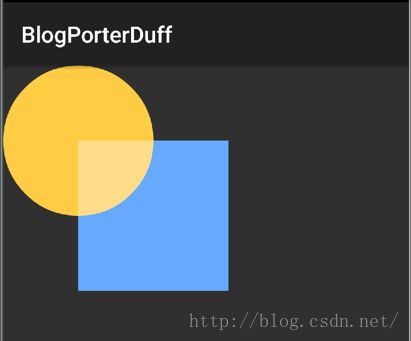
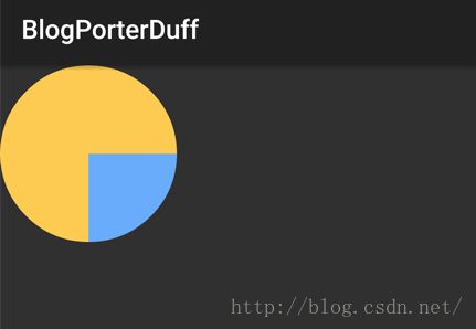
在开始讲解之前,我们随便拿一个效果图来看一下,我们在这个效果图中需要关注哪两点
对应代码:
canvas.drawBitmap(dstBmp, 0, 0, mPaint);
mPaint.setXfermode(new PorterDuffXfermode(PorterDuff.Mode.LIGHTEN));
canvas.drawBitmap(srcBmp,width/2,height/2, mPaint);
前面在讲canvas的脏区域更新时,已经提到,在最后一句计算效果图像时,是以源图像所在区域为计算目标的,把计算后的源图像更新到对应区域内。
所以如上图所示,我们在计算源图像所在区域效果图时,需要着重关注两个区域:
1、如图标示区域一:区域一是源图像和目标图像的相交区域,由于在这个区域源图像和目标图像像素都不是空白像素,所以可以明显看出颜色的计算效果。
2、如图标示区域二:在区域二中,源图像所在区域的目标图像是空白像素,所以这块区域所表示的意义就是,当某一方区域是空白像素时,此时的计算结果。
总而言之:我们在下面的各个模式计算时,只需要关注图示中的区域一和区域二;其中区域一表示当源图像和目标图像像素都不是空白像素时的计算结果,而区域二则表示当某一方区域是空白像素时,此时的计算结果。
一、颜色叠加相关模式
这部分涉及到的几个模式有Mode.ADD(饱和度相加)、Mode.DARKEN(变暗),Mode.LIGHTEN(变亮)、Mode.MULTIPLY(正片叠底)、Mode.OVERLAY(叠加),Mode.SCREEN(滤色)1、Mode.ADD(饱和度相加)
它的公式是Saturate(S + D);ADD模式简单来说就是对SRC与DST两张图片相交区域的饱和度进行相加同样使用上篇中的示例,一个矩形,一个圆形来做相加
代码如下:(再次帖出代码,这将是最后一次帖出示例代码了,下面都是基于这个例子的基础上,具体的代码讲解,上篇已经讲过,这里就不再缀述了)
public class MyView extends View {
    private int width = 400;
    private int height = 400;
    private Bitmap dstBmp;
    private Bitmap srcBmp;
    private Paint mPaint;

    public MyView(Context context, AttributeSet attrs) {
        super(context, attrs);
        setLayerType(View.LAYER_TYPE_SOFTWARE, null);
        srcBmp = makeSrc(width, height);
        dstBmp = makeDst(width, height);
        mPaint = new Paint();
    }

    @Override
    protected void onDraw(Canvas canvas) {
        super.onDraw(canvas);

        int layerID = canvas.saveLayer(0,0,width*2,height*2,mPaint,Canvas.ALL_SAVE_FLAG);

        canvas.drawBitmap(dstBmp, 0, 0, mPaint);
        mPaint.setXfermode(new PorterDuffXfermode(PorterDuff.Mode.ADD));
        canvas.drawBitmap(srcBmp,width/2,height/2, mPaint);
        mPaint.setXfermode(null);

        canvas.restoreToCount(layerID);

    }

    // create a bitmap with a circle, used for the "dst" image
    static Bitmap makeDst(int w, int h) {
        Bitmap bm = Bitmap.createBitmap(w, h, Bitmap.Config.ARGB_8888);
        Canvas c = new Canvas(bm);
        Paint p = new Paint(Paint.ANTI_ALIAS_FLAG);

        p.setColor(0xFFFFCC44);
        c.drawOval(new RectF(0, 0, w, h), p);
        return bm;
    }

    // create a bitmap with a rect, used for the "src" image
    static Bitmap makeSrc(int w, int h) {
        Bitmap bm = Bitmap.createBitmap(w, h, Bitmap.Config.ARGB_8888);
        Canvas c = new Canvas(bm);
        Paint p = new Paint(Paint.ANTI_ALIAS_FLAG);

        p.setColor(0xFF66AAFF);
        c.drawRect(0, 0, w, h, p);
        return bm;
    }
}
与上篇文章唯一不同的地方在于,只是把模式改为了Mode.ADD
效果图如下:

从效果图中可以看出,只有源图与目标图像相交的部分的图像的饱和度产生了变化,没相交的部分是没有变的,因为对方的饱和度是0,当然不相交的位置饱和度是不会变的。
这个模式的应用范围比较少,暂时想不到哪里会用到;
2、Mode.LIGHTEN(变亮)
它的算法是: [Sa + Da - Sa*Da,Sc*(1 - Da) + Dc*(1 - Sa) + max(Sc, Dc)]圆形和矩形的效果图为:
这个效果比较容易理解,两个图像重合的区域才会有颜色值变化,所以只有重合区域才有变亮的效果,源图像非重合的区域,由于对应区域的目标图像是空白像素,所以直接显示源图像。
大家对公式其实不必理解,用过Photoshop的同学,应该都知道图层模式里的“变亮”模式,在博客《自定义控件三部曲之绘图篇(九)——Paint之setColorFilter》中已经讲过在photoshop中的操作方法。
所以大家想知道结果,直接拿目标图像和源图像在photoshop中模拟一下就可以得到结果;
我们在实际应用中,会有下面的这个情况,当选中一本书时,给这本书加上灯光效果
其实它是两张图合成的:
DST:目标图像
SRC:源图像
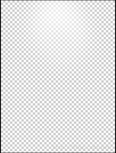
可以看到,在这张图片的最上方中间的位置有些白色半透明的填充,其它位置都是透明的。
下面我们来看一下代码:
public class LightBookView extends View {
    private Paint mBitPaint;
    private Bitmap BmpDST,BmpSRC;

    public LightBookView(Context context, AttributeSet attrs) {
        super(context, attrs);
        mBitPaint = new Paint();
        BmpDST = BitmapFactory.decodeResource(getResources(),R.drawable.book_bg,null);
        BmpSRC = BitmapFactory.decodeResource(getResources(),R.drawable.book_light,null);
    }

    @Override
    protected void onDraw(Canvas canvas) {
        super.onDraw(canvas);

        int layerId = canvas.saveLayer(0, 0, getWidth(), getHeight(), null, Canvas.ALL_SAVE_FLAG);
        //先画书架,做为目标图像
        canvas.drawBitmap(BmpDST,0,0,mBitPaint);
        mBitPaint.setXfermode(new PorterDuffXfermode(PorterDuff.Mode.LIGHTEN));
        //再图光点
        canvas.drawBitmap(BmpSRC,0,0,mBitPaint);

        mBitPaint.setXfermode(null);
        canvas.restoreToCount(layerId);

    }
}
意思就是先把书架做为目标图像画在底层,然后给mBitPaint设置上PorterDuffXfermode,然后将处理过的源图盖在目标图像上。代码难度不大,就不再细讲。
3、Mode.DARKEN(变暗)
对应公式是: [Sa + Da - Sa*Da,Sc*(1 - Da) + Dc*(1 - Sa) + max(Sc, Dc)]示例图像为:

同样是对应photoshop中的混合模式中的变暗模式;同样大家可以在photoshop中就可以得到效果,就不再细讲了。
4、Mode.MULTIPLY(正片叠底)
公式是:[Sa * Da, Sc * Dc]示例图像为:
有些同学会奇怪了,Photoshop中也有正片叠底啊,相交区域正片叠底后的颜色确实是绿色的,但源图像的非相交区域怎么没了?
我们来看下他的计算公式:[Sa * Da, Sc * Dc],在计算alpha值时的公式是Sa * Da,是用源图像的alpha值乘以目标图像的alpha值;由于源图像的非相交区域所对应的目标图像像素的alpha是0,所以结果像素的alpha值仍是0,所以源图像的非相交区域在计算后是透明的。
在两个图像的相交区域的混合方式是与photoshop中的正片叠底效果是一致的。
5、Mode.OVERLAY(叠加)
这个没有给出公式……示例图像为:
虽然没有给出公式,但从效果图中可以看到,源图像交合部分有效果,非交合部分依然是存在的,这就可以肯定一点,当目标图像透明时,在这个模式下源图像的色值不会受到影响;
6、Mode.SCREEN(滤色)
对应公式是:[Sa + Da - Sa * Da, Sc + Dc - Sc * Dc]示例图像为:
同样,只是源图像与目标图像交合部分有效果,源图像非交合部分保持原样。
到这里,这六种混合模式就讲完了,我们下面总结一下:
1、这几种模式都是PhotoShop中存在的模式,是通过计算改变交合区域的颜色值的
2、除了Mode.MULTIPLY(正片叠底)会在目标图像透明时将结果对应区域置为透明,其它图像都不受目标图像透明像素影响,即源图像非交合部分保持原样。
7、示例——twitter标识的描边效果
由于这些模式在photoshop中都存在,直接拿目标图像和源图像在photoshop中就可以演示出来,就没有多举例子,其实,在实现时实现两图像混合时,也经常会用到这些模式的,比如这里twitter的暗光效果我们这里有两张源图:
图一:
图二:
然后完成的效果如下:
我们先想想这个要实现的效果有哪些特性:
首先,
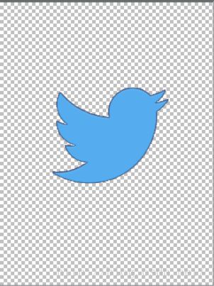
在图一中,小鸟整个都是蓝色的
在图二中,只有小鸟的边缘部分是白色的,中间部分是透明的。
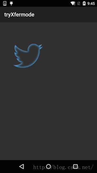
在最终的合成图中:图一和图二中小鸟与边缘的是显示的,而且还有某种效果,但小鸟中间的区域变透明了!显示的是底部Activity的背景色。
想到我们前面学到的几种样式中,只有Mode.MULTIPLY(正片叠底)会在两个图像的一方透明时,结果像素就是透明的。所以这里使用的模式就是Mode.MULTIPLY
对应代码如下:
public class TwitterView extends View {
    private Paint mBitPaint;
    private Bitmap BmpDST,BmpSRC;
    public TwitterView(Context context, AttributeSet attrs) {
        super(context, attrs);
        mBitPaint = new Paint();
        BmpDST = BitmapFactory.decodeResource(getResources(),R.drawable.twiter_bg,null);
        BmpSRC = BitmapFactory.decodeResource(getResources(),R.drawable.twiter_light,null);
    }

    @Override
    protected void onDraw(Canvas canvas) {
        super.onDraw(canvas);

        int layerId = canvas.saveLayer(0, 0, getWidth(), getHeight(), null, Canvas.ALL_SAVE_FLAG);

        canvas.drawBitmap(BmpDST,0,0,mBitPaint);
        mBitPaint.setXfermode(new PorterDuffXfermode(PorterDuff.Mode.MULTIPLY));
        canvas.drawBitmap(BmpSRC,0,0,mBitPaint);

        mBitPaint.setXfermode(null);
        canvas.restoreToCount(layerId);
    }
}
二、SRC相关模式
在讲完了photoshop中存在的几个模式以后,还有几个是在处理结果时以源图像显示为主的几个模式,所以大家在遇到当图像相交时,需要显示源图像时,就需要从这几个模式中考虑了这部分所涉及的模式有:Mode.SRC、Mode.SRC_IN、Mode.SRC_OUT、Mode.SRC_OVER、Mode.SRC_ATOP
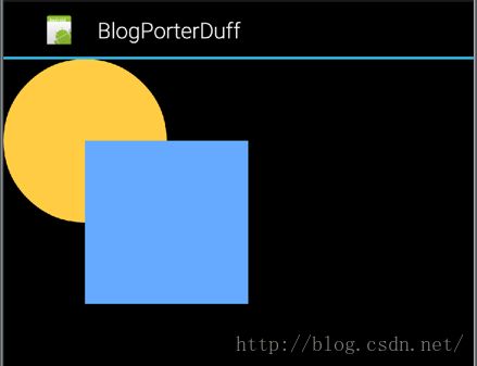
1、Mode.SRC
计算公式为:[Sa, Sc]从公式中也可以看出,在处理源图像所在区域的相交问题时,全部以源图像显示
所以示例图像为:
2、Mode.SRC_IN
计算公式为:[Sa * Da, Sc * Da]在这个公式中结果值的透明度和颜色值都是由Sa,Sc分别乘以目标图像的Da来计算的。所以当目标图像为空白像素时,计算结果也将会为空白像素。
示例图像为:
大家注意SRC_IN模式与SRC模式的区别,一般而言,是在相交区域时无论SRC_IN还是SRC模式都是显示源图像,而唯一不同的是,当目标图像是空白像素时,在SRC_IN所对应的区域也将会变成空白像素;
其实更严格的来讲,SRC_IN模式是在相交时利用目标图像的透明度来改变源图像的透明度和饱和度。当目标图像透明度为0时,源图像就完全不显示。
利用这个特性,我们能完成很多功能,比如:
示例1:图形圆角
我们有两张图像:图像一:(我们熟悉的小狗 )
图像二:(去角遮罩)
效果为:
可以看到这个遮罩的四个角都是圆形切角,都是透明的。
现在我们需要利用SRC_IN的特性,显示SRC图像,但会把目标图像中空白像素的部分去掉的特性来做了。
由于我们需要最终显示小狗图像,所以这里需要将小狗 图像做为SRC,将遮罩做为目标图像
代码为:
public class RoundImageView_SRCIN extends View {
    private Paint mBitPaint;
    private Bitmap BmpDST,BmpSRC;

    public RoundImageView_SRCIN(Context context, AttributeSet attrs) {
        super(context, attrs);
        setLayerType(View.LAYER_TYPE_SOFTWARE, null);
        mBitPaint = new Paint();
        BmpDST = BitmapFactory.decodeResource(getResources(),R.drawable.dog_shade,null);
        BmpSRC = BitmapFactory.decodeResource(getResources(),R.drawable.dog,null);
    }


    @Override
    protected void onDraw(Canvas canvas) {
        super.onDraw(canvas);

        int layerId = canvas.saveLayer(0, 0, getWidth(), getHeight(), null, Canvas.ALL_SAVE_FLAG);

        canvas.drawBitmap(BmpDST,0,0,mBitPaint);
        mBitPaint.setXfermode(new PorterDuffXfermode(PorterDuff.Mode.SRC_IN));
        canvas.drawBitmap(BmpSRC,0,0,mBitPaint);

        mBitPaint.setXfermode(null);
        canvas.restoreToCount(layerId);
    }
}
示例2:图片倒影
前面我们讲过,SRC_IN模式是在相交时利用目标图像的透明度来改变源图像的透明度和饱和度。所以当目标图像的透明度在0-255之间时,就会把源图像的透明度和颜色值都会变小。利用这个特性,我们可以做出倒影效果
用到的遮罩为:
这个遮罩好像还不太清,它是一个从上到下的白色填充渐变;白色的透明度从49%到0;
对应的代码为:
public class InvertedImageView_SRCIN  extends View{
    private Paint mBitPaint;
    private Bitmap BmpDST,BmpSRC,BmpRevert;
    public InvertedImageView_SRCIN(Context context, AttributeSet attrs) {
        super(context, attrs);
        setLayerType(View.LAYER_TYPE_SOFTWARE, null);
        mBitPaint = new Paint();
        BmpDST = BitmapFactory.decodeResource(getResources(),R.drawable.dog_invert_shade,null);
        BmpSRC = BitmapFactory.decodeResource(getResources(),R.drawable.dog,null);

        Matrix matrix = new Matrix();
        matrix.setScale(1F, -1F);
        // 生成倒影图
        BmpRevert = Bitmap.createBitmap(BmpSRC, 0, 0, BmpSRC.getWidth(), BmpSRC.getHeight(), matrix, true);
    }

    @Override
    protected void onDraw(Canvas canvas) {
        super.onDraw(canvas);

        //先画出小狗图片
        canvas.drawBitmap(BmpSRC,0,0,mBitPaint);

        //再画出倒影
        int layerId = canvas.saveLayer(0, 0, getWidth(), getHeight(), null, Canvas.ALL_SAVE_FLAG);
        canvas.translate(0,BmpSRC.getHeight());

        canvas.drawBitmap(BmpDST,0,0,mBitPaint);
        mBitPaint.setXfermode(new PorterDuffXfermode(PorterDuff.Mode.SRC_IN));
        canvas.drawBitmap(BmpRevert,0,0,mBitPaint);

        mBitPaint.setXfermode(null);

        canvas.restoreToCount(layerId);
    }
}
代码中稍微有点难度的地方,可能是在利用小狗图片生成对应的倒影图像的位置:
Matrix matrix = new Matrix();
matrix.setScale(1F, -1F);
// 生成倒影图
BmpRevert = Bitmap.createBitmap(BmpSRC, 0, 0, BmpSRC.getWidth(), BmpSRC.getHeight(), matrix, true);
这里主要是利用matrix将图像做一个翻转,有关位移matrix的知识,我们会在讲解canvas的变换时细讲,这里就不再讲解了,继续关注吧。
SRC_IN模式就讲这两个例子吧,其实它的用途是很多的,比如扣图,你能否利用我们圆角示例的来实现一个扣图效果呢?自己试试吧
3、Mode.SRC_OUT
计算公式为:[Sa * (1 - Da), Sc * (1 - Da)]从公式中可以看出,计算结果的透明度=Sa * (1 - Da);也就是说当目标图像图像完全透明时,计算结果将是透明的;
示例图像为:

从示例图中也可以看出,源图像与目标图像的相交部分由于目标图像的透明度为100%,所以相交部分的计算结果为空白像素。在目标图像为空白像素时,完全以源图像显示。
所以这个模式的特性可以概括为:以目标图像的透明度的补值来调节源图像的透明度和色彩饱和度。即当目标图像为空白像素时,就完全显示源图像,当目标图像的透明度为100%时,交合区域为空像素。
Mode.SRC_OUT简单来说,当目标图像有图像时结果显示空白像素,当目标图像没有图像时,结果显示源图像。
1、橡皮擦效果
利用这个特性,我们可以实现橡皮擦效果原理:我们说了简单来讲Mode.SRC_OUT模式,当目标图像有图像时计算结果为空白像素,当目标图像没有图像时,显示源图像;
所以我们把手指轨迹做为目标图像,在与源图像计算时,有手指轨迹的地方就变为空白像素了,看起来的效果就是被擦除了。
代码如下:
public class DogView_SRCOUT extends View {
    private Paint mBitPaint;
    private Bitmap BmpDST,BmpSRC;
    private Path mPath;
    private float mPreX,mPreY;
    public DogView_SRCOUT(Context context, AttributeSet attrs) {
        super(context, attrs);

        setLayerType(View.LAYER_TYPE_SOFTWARE, null);
        mBitPaint = new Paint();
        mBitPaint.setColor(Color.RED);
        mBitPaint.setStyle(Paint.Style.STROKE);
        mBitPaint.setStrokeWidth(45);

        BmpSRC = BitmapFactory.decodeResource(getResources(),R.drawable.dog,null);
        BmpDST = Bitmap.createBitmap(BmpSRC.getWidth(), BmpSRC.getHeight(), Bitmap.Config.ARGB_8888);
        mPath = new Path();
    }

    @Override
    protected void onDraw(Canvas canvas) {
        super.onDraw(canvas);

        int layerId = canvas.saveLayer(0, 0, getWidth(), getHeight(), null, Canvas.ALL_SAVE_FLAG);

        //先把手指轨迹画到目标Bitmap上
        Canvas c = new Canvas(BmpDST);
        c.drawPath(mPath,mBitPaint);

        //然后把目标图像画到画布上
        canvas.drawBitmap(BmpDST,0,0,mBitPaint);

        //计算源图像区域
        mBitPaint.setXfermode(new PorterDuffXfermode(PorterDuff.Mode.SRC_OUT));
        canvas.drawBitmap(BmpSRC,0,0,mBitPaint);

        mBitPaint.setXfermode(null);
        canvas.restoreToCount(layerId);
    }


    @Override
    public boolean onTouchEvent(MotionEvent event) {
        switch (event.getAction()){
            case MotionEvent.ACTION_DOWN:
                mPath.moveTo(event.getX(),event.getY());
                mPreX = event.getX();
                mPreY = event.getY();
                return true;
            case MotionEvent.ACTION_MOVE:
                float endX = (mPreX+event.getX())/2;
                float endY = (mPreY+event.getY())/2;
                mPath.quadTo(mPreX,mPreY,endX,endY);
                mPreX = event.getX();
                mPreY =event.getY();
                break;
            case MotionEvent.ACTION_UP:
                break;
        }
        postInvalidate();
        return super.onTouchEvent(event);
    }
}
首先这里涉及到使用贝赛尔曲线构造手指轨迹的知识,请参考 《自定义控件三部曲之绘图篇(六)——Path之贝赛尔曲线和手势轨迹、水波纹效果
》
代码难度不大就不再讲了,既然我们实现了擦除效果,那我们稍微加以改进,就变成了刮刮卡效果了
2、刮刮卡效果
首先,搞一个刮刮卡图片:(guaguaka_pic.png)
然后再搞个中奖结果:(guagua_text.png)
结果如下:
对应代码为:
public class GuaGuaCardView_SRCOUT extends View{
    private Paint mBitPaint;
    private Bitmap BmpDST,BmpSRC,BmpText;
    private Path mPath;
    private float mPreX,mPreY;
    public GuaGuaCardView_SRCOUT(Context context, AttributeSet attrs) {
        super(context, attrs);

        setLayerType(View.LAYER_TYPE_SOFTWARE, null);
        mBitPaint = new Paint();
        mBitPaint.setColor(Color.RED);
        mBitPaint.setStyle(Paint.Style.STROKE);
        mBitPaint.setStrokeWidth(45);

        BmpText = BitmapFactory.decodeResource(getResources(),R.drawable.guaguaka_text,null);
        BmpSRC = BitmapFactory.decodeResource(getResources(),R.drawable.guaguaka_pic,null);
        BmpDST = Bitmap.createBitmap(BmpSRC.getWidth(), BmpSRC.getHeight(), Bitmap.Config.ARGB_8888);
        mPath = new Path();
    }

    @Override
    protected void onDraw(Canvas canvas) {
        super.onDraw(canvas);

        canvas.drawBitmap(BmpText,0,0,mBitPaint);

        int layerId = canvas.saveLayer(0, 0, getWidth(), getHeight(), null, Canvas.ALL_SAVE_FLAG);

        //先把手指轨迹画到目标Bitmap上
        Canvas c = new Canvas(BmpDST);
        c.drawPath(mPath,mBitPaint);

        //然后把目标图像画到画布上
        canvas.drawBitmap(BmpDST,0,0,mBitPaint);

        //计算源图像区域
        mBitPaint.setXfermode(new PorterDuffXfermode(PorterDuff.Mode.SRC_OUT));
        canvas.drawBitmap(BmpSRC,0,0,mBitPaint);

        mBitPaint.setXfermode(null);
        canvas.restoreToCount(layerId);
    }

    @Override
    public boolean onTouchEvent(MotionEvent event) {
        switch (event.getAction()){
            case MotionEvent.ACTION_DOWN:
                mPath.moveTo(event.getX(),event.getY());
                mPreX = event.getX();
                mPreY = event.getY();
                return true;
            case MotionEvent.ACTION_MOVE:
                float endX = (mPreX+event.getX())/2;
                float endY = (mPreY+event.getY())/2;
                mPath.quadTo(mPreX,mPreY,endX,endY);
                mPreX = event.getX();
                mPreY =event.getY();
                break;
            case MotionEvent.ACTION_UP:
                break;
        }
        postInvalidate();
        return super.onTouchEvent(event);
    }
}
与上面橡皮擦效果不同的是,在绘图时,在特效前先把刮刮卡的中奖文字绘在底部,这时候当橡皮擦把刮刮卡的图片给擦除掉时,就露出底部的刮刮卡的中奖文字了。
4、Mode.SRC_OVER
计算公式为:[Sa + (1 - Sa)*Da, Rc = Sc + (1 - Sa)*Dc]示例图像为:

我们可以看到,在计算结果中,源图像没有变。它的意思就是在目标图像的顶部绘制源图像。从公式中也可以看出目标图像的透明度为Sa + (1 - Sa)*Da;即在源图像的透明度基础上增加一部分目标图像的透明度。增加的透明度是源图像透明度的补量;目标图像的色彩值的计算方式同理,所以当源图像透明度为100%时,就原样显示源图像;
5、Mode.SRC_ATOP
计算公式为:[Da, Sc * Da + (1 - Sa) * Dc]示例图像为:
很奇怪,它的效果图竟然与SRC_IN模式是相同的,我们来对比一下它们的公式:
SRC_IN: [Sa * Da, Sc * Da]
SRC_ATOP:[Da, Sc * Da + (1 - Sa) * Dc]
先看透明度:在SRC_IN中是Sa * Da,在SRC_ATOP是Da
SRC_IN是源图像透明度乘以目标图像的透明度做为结果透明度,而SRC_ATOP是直接使用目标图像的透明度做为结果透明度
再看颜色值:
SRC_IN的颜色值为 Sc * Da,SRC_ATOP的颜色值为Sc * Da + (1 - Sa) * Dc;SRC_ATOP在SRC_IN的基础上还增加了(1 - Sa) * Dc;
所以总结来了:
1、当透明度只有100%和0%时,SRC_ATOP是SRC_IN是通用的
2、当透明度不只有100%和0%时,SRC_ATOP相比SRC_IN源图像的饱和度会增加,即会显得更亮!
所以,前面利用SRC_IN实现的圆角效果是完全可以使用SRC_OUT模式来实现的
1、圆角效果(当透明度只有100%和0%时,SRC_ATOP是SRC_IN是通用的)
效果图不变:代码中仅将SRC_IN模式改为SRC_OUT模式即可:
public class RoundImageView_SRCOUT extends View {
    private Paint mBitPaint;
    private Bitmap BmpDST,BmpSRC;

    public RoundImageView_SRCOUT(Context context, AttributeSet attrs) {
        super(context, attrs);
        setLayerType(View.LAYER_TYPE_SOFTWARE, null);
        mBitPaint = new Paint();
        BmpDST = BitmapFactory.decodeResource(getResources(),R.drawable.dog_shade,null);
        BmpSRC = BitmapFactory.decodeResource(getResources(),R.drawable.dog,null);
    }


    @Override
    protected void onDraw(Canvas canvas) {
        super.onDraw(canvas);

        int layerId = canvas.saveLayer(0, 0, getWidth(), getHeight(), null, Canvas.ALL_SAVE_FLAG);

        canvas.drawBitmap(BmpDST,0,0,mBitPaint);
        mBitPaint.setXfermode(new PorterDuffXfermode(PorterDuff.Mode.SRC_OUT));
        canvas.drawBitmap(BmpSRC,0,0,mBitPaint);

        mBitPaint.setXfermode(null);
        canvas.restoreToCount(layerId);
    }
}
示例2:图片倒影(颜色饱和度增加)
前面我们讲过,当目标图像的透明度不是100%和0%时,源图像的颜色值就会比SRC_IN模式的颜色值饱和度增加。我们来对比下效果:
同样只需要在将原图片倒影代码的SRC_IN模式改成SRC_OUT即可,代码如下:
public class InvertedImageView_SRCOUT extends View{
    private Paint mBitPaint;
    private Bitmap BmpDST,BmpSRC,BmpRevert;
    public InvertedImageView_SRCOUT(Context context, AttributeSet attrs) {
        super(context, attrs);
        setLayerType(View.LAYER_TYPE_SOFTWARE, null);
        mBitPaint = new Paint();
        BmpDST = BitmapFactory.decodeResource(getResources(),R.drawable.dog_invert_shade,null);
        BmpSRC = BitmapFactory.decodeResource(getResources(),R.drawable.dog,null);

        Matrix matrix = new Matrix();
        matrix.setScale(1F, -1F);
        // 生成倒影图
        BmpRevert = Bitmap.createBitmap(BmpSRC, 0, 0, BmpSRC.getWidth(), BmpSRC.getHeight(), matrix, true);
    }

    @Override
    protected void onDraw(Canvas canvas) {
        super.onDraw(canvas);

        //先画出小狗图片
        canvas.drawBitmap(BmpSRC,0,0,mBitPaint);

        //再画出倒影
        int layerId = canvas.saveLayer(0, 0, getWidth(), getHeight(), null, Canvas.ALL_SAVE_FLAG);
        canvas.translate(0,BmpSRC.getHeight());

        canvas.drawBitmap(BmpDST,0,0,mBitPaint);
        mBitPaint.setXfermode(new PorterDuffXfermode(PorterDuff.Mode.SRC_IN));
        canvas.drawBitmap(BmpRevert,0,0,mBitPaint);

        mBitPaint.setXfermode(null);

        canvas.restoreToCount(layerId);
    }
}
效果图如下:

然后再来看看原来SRC_IN的效果图,对比一下:
明显亮度是有增加的。
所以对于SRC_ATOP的结论就出来了,一般而言SRC_ATOP是可以和SRC_IN通用的,但SRC_ATOP所产生的效果图在目标图不是透明度不是0或100%的时候,会比SRC_IN模式产生的图像更亮些;
好了,这篇就先到这里了,下篇继续给大家讲解xfermode的应用。
如果本文有帮到你,记得加关注哦
源码下载地址:http://download.csdn.net/detail/harvic880925/9507075
请大家尊重原创者版权,转载请标明出处:http://blog.csdn.net/harvic880925/article/details/51284710 谢谢
如果你喜欢我的文章,那么你将会更喜欢我的微信公众号,将定期推送博主最新文章与收集干货分享给大家(一周一次)


