AMP Logical Link Creation
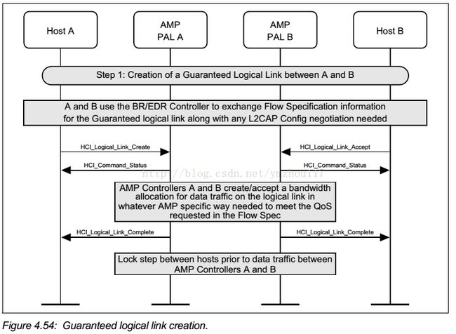
Step 1:Host A sends a Logical Link Create command to its AMP Controller. AMP Controllers A and B dowhatever AMP specific action is required to meet the bandwidth request. EachAMP Controller sends the Logical Link Creation Complete event to its host. Bothdevices can now pass data traffic over the AMP channel.
A flow diagram of the establishment of a Guaranteed logical connection between two devices is shown in Figure 4.54.
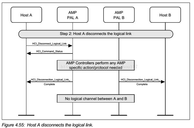
Step 2:Host A sendsa Logical Link Disconnect command to its AMP Controller. AMP Controllers A andB do whatever AMP specific action is required to meet the request. Each AMP Controller sends the Logical Link Disconnect Complete event to its host.
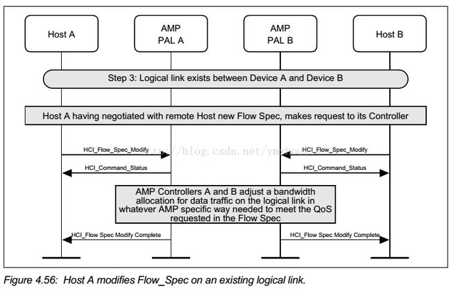
Step 3:During normal operation the Host may modify logical link characteristics.