
Introduction
Workload Deployer and PureApplication Systems come with predefined pattern types and plug-ins that incorporate years of expertise and best practices to address specific workload solutions. They are application-centric (as opposed to middleware-centric) because they allow you to focus on the application itself rather than on the required hardware or architecture.
The idea is that you specify an existing application (for example, an .ear file), and a set of policies that correspond to the service level agreement (SLA) you wish to achieve, and let Workload Deployer or PureApplication Systems transform that input into an installed, configured, and integrated middleware solution. You do not directly create the required topology. As the application runs, additional nodes, such as caching nodes, app server nodes, and web proxy nodes, are automatically added or removed driven by the policies you establish to keep performance acceptable. The deployed virtual application pattern is called a virtual application instance, or simply a virtual application.
Virtual application patterns promise to save time and money by offering a paradigm shift in the way we deliver cloud solutions. However, this dynamic behavior of virtual application patterns is not free. Unless you use one of the predefined pattern types and plug-ins to get this type of functionality, you need to develop one or more plug-ins. While plug-ins are generally easy to use, developing them can be seen as a daunting task. We intend to change that perception with this series and encourage more plug-in development.
This article series consist of three parts:
- Creating plug-ins for virtual application patterns, Part 1: An introduction (this article)
- Creating plug-ins for virtual application patterns, Part 2: A closer look (future article)
- Creating plug-ins for virtual application patterns, Part 3: Design considerations (future article)
Prerequisites
To follow along in this article, you will need to download and install the following items:
- The IBM Workload Plug-in Development Kit (PDK): You can download this kit from the GUI in Workload Deployer or PureApplication Systems using the Download Tooling menu that appears in the Welcome page. You can also download it directly from the IBM Workload Plugin Development Kit page. The version used in these articles is PDK v1.0.0.6.
If you have not done so already, you will be asked to first register for an IBM Common Profile Account.
- Eclipse Helios 3.6 SR2 or later (32-bit): Download from the eclipse.org site. The Java EE Developers package is recommended.
- Java 6 JDK 32-bit: Download from the Java site.
- Apache Ant 7.1 or higher: Download from the Apache Ant site.
Make sure you use the exact software versions described above. Eclipse is optional; you do not need it to build plug-ins for virtual application patterns, but we highly recommend it because it simplifies some of the work involved in creating plug-ins. We chose it as the development tool for this article series. If you use Eclipse, you can optionally use the Ant tool that comes in the Eclipse installation directory:
<eclipse-installation-directory>/ plugins/org.apache.ant_1.*
Back to top
Preparing your environment
The following section gives you an abridged version of how to install the necessary components and prepare your Eclipse environment to work with plug-ins. This is enough to get you started, but, if you need more information, consult the Information Center for IBM Workload Deployer orIBM PureApplication Systems, as well as the Plug-in Developer's Guide that comes with the PDK.
Installing and building the plug-in development components
Once you download all the necessary software, follow these steps:
- Create a directory for the PDK and extract the pdk-1.0.0.6 zip file there.
- Install Ant.
- Set the
ANT_HOMEenvironment variable to the directory where you installed Ant. - Add the
Antbin directory to your path. - Install the Java 6 JDK 32 bit.
- Set the
JAVA_HOMEenvironment variable to point to your Java installation directory. - Add the Java bin directory to your path.
- Go to the directory where you extracted the PDK zip package, and run Ant from the command line to build the plug-in development components (simply type
antand press Enter).
Eclipse PDK environment setup
Installing and configuring Eclipse for plug-in development involves the following steps:
- Install Eclipse Helios 3.6 SR2 32-bit or later version (32-bit).
- Start Eclipse.
- Within the Eclipse workspace, click Help > Install New Software to bring up the "Available Software" window.
- Click Add to add a new software repository, and then Archive to point to the archive: com.ibm.maestro.plugin.pdk.site.zip.
- Give the repository a name, such as
Workload Deployer Eclipse Plug-in, and click OK. - Wait for the Name area to display "IBM Workload Plugin Development Kit", and click Select All.
- Uncheck the box labeled Contact all update sites during the install to find the required software.
- Click Next and wait for the installation to complete.
After configuring your environment correctly, you are ready to begin creating pattern types and plug-ins. In this article, we walk you through a simple example that will help get you started with developing plug-ins, but first let us review some basic terms and concepts.
Back to top
Creating virtual application patterns
Whether you use existing pattern types and plug-ins or create your own, once they have been loaded into the Workload Deployer or PureApplication System catalog, you can use them to build virtual application patterns. You do this using the Virtual Application Builder included with the GUI. Figure 1 illustrates how to open the Virtual Application Builder:
- Depending on which system you are using, Workload Deployer or PureApplication System, choose Patterns > Virtual Applications orWorkload Console > Patterns > Virtual Applications. Click the green plus sign to start a new pattern.
- In the Create Application dialog, select the Pattern Type and the corresponding template you wish to work with. Then click Start Building.
You build a virtual application pattern according to a specific pattern type and an optional template. For example, to build a standard JEE web application, you can choose the Web Application Pattern Type 2.0 and the template Blank Java EE web application. Templates are previously created patterns that you save as application templates for reuse.
Figure 1. Starting the Virtual Application Builder

Click Start Building to open the Virtual Application Builder.
Figure 2. The Virtual Application Builder

Figure 2 illustrates how the Virtual Application Builder works. After you select a pattern type using an optional template, and open the builder, the Resource Palette shows a list of assets that you can use to build your pattern. These assets consist of components, links, and policies that the associated plug-ins expose. You drag and drop components from the Resource Palette onto the canvas, and create links between them. You can apply policies to individual components or to the entire pattern, in which case they would be applied to every component that has such a policy defined in its model.
Clicking an element on the canvas shows its configurable properties in the Property Editor. These properties are attributes that you can customize. Figure 2 shows them as circled "A's". Components, policies, and links can all have configurable properties.
As you build an application, the back-end of the Virtual Application Builder scans the artifacts associated with the plug-in to help guide the modeling according to how the plug-in intends. The implementation and maintenance details of components, policies, and links are all encapsulated within the plug-in itself.
Different views of your pattern
What you see by default in the Virtual Application Builder is a Diagram View of your pattern. You can also view the pattern in List View and Source View formats as shown in Figure 3. Here is a brief description of what those views are:
- The Diagram View allows you to graphically build the topology and provides many visual cues along the way. It is useful while initially designing the virtual application pattern.
- The List View lets you easily see all the attributes that need to be configured by a given virtual application pattern design.
- The Source View displays read-only content. It is a serialization of the pattern shown in the Diagram view. This is a good place to start if you get errors trying to deploy your pattern.
Figure 3. Different views of a virtual application pattern

Back to top
Pattern types and plug-ins
Figure 4 shows the high-level relationship between pattern types and plug-ins. A pattern type denotes a collection of plug-ins which, together, determine which resources appear in the Resource Palette, and which attributes can be configured in the Virtual Application Builder. Plug-ins expose components, links, and policies, which you use to build the pattern. They also determine how an application is built, configured, deployed, and managed throughout its lifecycle.
A pattern type logically groups a set of related plug-ins to support a specific type of workload solution. Because of this, pattern types are also called workload models.
You can create your own pattern types to address a custom workload or extend an existing pattern type with additional plug-ins.
Figure 4. Pattern types and plug-ins

Back to top
A simple example
This first article presents a simple example that consists of a pattern type and a plug-in containing two components and a link, as seen in Figure 5.
Figure 5. Our simple example

The pattern type and the plug-in allow you to build a basic virtual application pattern that connects one component to the other. Each component has an attribute that can be customized. The link enables you to connect Simple Component 1 to Simple Component 2, but does not create any real dependencies or facilitate any interaction between the two.
We do not go beyond that in this first article since it already gives us plenty to discuss. The idea is to first give you a solid understanding of the basic concepts before moving on to other topics in subsequent articles.
Back to top
From app model to virtual machines
Composing a virtual application pattern in the Virtual Application Builder creates a logical description or application model of the virtual application. Your saved work becomes a JSON document called the app model. During deployment, this app model or metadata is converted to a topology document, which is a physical description of the topology that makes up the virtual application. Workload Deployer and PureApplication System know how to deploy the topology document as a collection of virtual machines, as well as how to install and configure software on them.
Components in a virtual application pattern usually denote one or more deployed virtual machines while links represent dependencies between them. This may not always be the case, however, since the application model is independent of the topology document. Artifacts you drag onto the canvas are only those parts of the logical model that plug-ins expose so that you can build the virtual application pattern according to the design offered by the plug-in.
The conversion steps from a logical model to a physical document are actually defined within the plug-in itself.
Back to top
General steps for developing a plug-in
Follow the steps below to develop a pattern type and an associated plug-in using the Eclipse PDK. This article walks you through each of these steps:
- Create a pattern type project.
- Update the generated
patterntype.jsonfile to fit your project's needs. - Create a new plug-in project.
- Update the
plugin/appmodel/metadata.jsonfile to define the configurable application model components that should be exposed in the Virtual Application Builder. - Update the generated
plugin/config.jsonfile to fit your project's needs. - Create the parts and nodeparts that need to be installed on the virtual machines.
- Create additional roles as needed.
- Update the generated life cycle scripts.
- Create the OSGi service components. If you are using the Eclipse PDK, this step will automatically do the following:
- Generate the .vm templates or .java source files to transform the application model to a topology document.
- Create the corresponding service declaration .xml files.
- Update the plug-in's META-INF/MANIFEST.MF file to reference the new OSGi service components.
- Update the default velocity templates.
- Build the pattern type (or plug-in) and export the resulting .tgz file to the file system.
- Import the pattern type or plug-in into Workload Deployer or PureApplication System, and use the plug-in to build a virtual application pattern.
Creating a pattern type for a new plug-in is not mandatory. You can also add your new plug-in to an existing pattern type.
Back to top
Step 1: Create a pattern type project
Within Eclipse, to create a pattern type, perform the following steps:
- Choose File > New > Other...and select IBM Workload Plug-in Development > IBM Workload Pattern Type Project.
- Click Next.
- Give your project a name and use the same name for the Pattern type name field. The name used in this example is
patterntypeSimple. - For the Pattern type version field, use
1.0.0.0. - Click Finish. If Eclipse asks if you want to switch to the Workload Plug-in Development perspective, reply Yes.
- These steps create a directory structure for the pattern type, with the file
patterntype.jsonin its root folder, as shown in Figure 6.Figure 6. Generated skeleton code for a new pattern type project
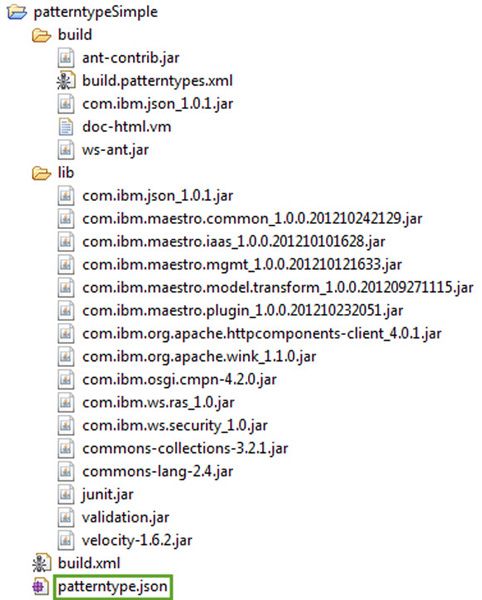
Eclipse adds additional items to the project, such as the Tivoli® maestro libraries and Ant-ready build files, to help facilitate the process of creating the pattern type. The build directory contains the build.patterntypes.xml file and the Ant .jar files used to build the pattern type. The lib folder includes the .jar files needed for compiling the project, and build.xml is the Ant build file required to build the pattern type project. The file patterntype.json holds the details of the pattern type. In a sense, the pattern type project is self-sufficient, meaning all the libraries and scripts necessary to build it are included in the project itself. The same is true for plug-in projects.
The JSON Editor
The Eclipse PDK environment includes a JSON Editor, which lets you easily edit and validate the content of a JSON file. From the Package Explorer view, if you double-click the patterntype.json file of the pattern type just created, the system shows you its content in the JSON editor. As illustrated in Figure 7, you can either work with the editor's Configuration view or its Source view. Making changes to one will automatically update the other. The JSON editor performs in-place validation of input, and displays errors, warnings, and tips, as necessary in the Configuration view.
Figure 7. Generated skeleton code for a new pattern type project

Back to top
Step 2: Update the patterntype.json file
The generated JSON source already has everything you need, so you do not need to modify the patterntype.json file for this example. Notice that the pattern type does not include any references to plug-ins. This is because plug-ins associate themselves with pattern types, and not the other way around.
Switch to the Source view, and make sure patterntype.json looks like the source code shown in Figure 7. If you make any changes, press Ctrl+Sto save your work.
Back to top
Step 3: Create a new plug-in project
To create a new plug-in project:
- If you are not already there, switch to the Workload Plug-in Development perspective via Window > Open Perspective > Other > Workload Plug-in Development perspective.
- Select File > New > Project > IBM Workload Plug-in Development > IBM Workload Plug-in Project. The IBM Workload Plug-in Project may also appear directly under Project. Click Next.
- In the New Project dialog, give the project and the new plug-in a name. For this example, use the name
pluginSimplefor both. - Check the Generate project skeleton and click Finish.
Eclipse will generate the directory structure shown in Figure 8.
Figure 8. Generated project skeleton for a new plug-in project
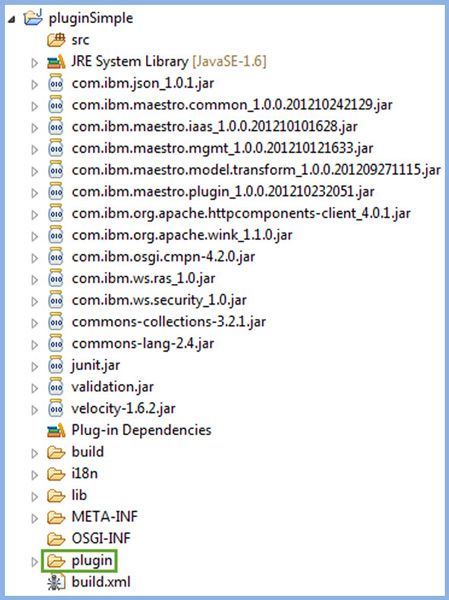
At first glance, the generated project may seem overwhelming just to get started with a simple example, but, in reality, outside of the plug-in directory, most of what you see consists of supporting files and libraries. Besides the Tivoli maestro libraries and the Ant-ready build files to help build the plug-in, there are other folders that get generated when you choose to generate the skeleton code of a new plug-in project. Table 1 provides a brief description.
Table 1. Folders automatically generated for a plug-in project
| Folder | Description |
|---|---|
| src | Contains any Java™ source code associated with OSGi service components. |
| build | Contains the build.plugins.xml file and the Ant .jar files used to build the plug-in. |
| i18n | Holds the translation files for plug-in localization. |
| lib | Includes the .jar files needed for compiling the plug-in project. |
| META-INF | Contains the manifest file for the plug-in. |
| OSGI-INF | Holds the OSGi service components. |
| plugin | Contains the config.json file as well as the plug-in configuration directory. |
| build.xml | This is the Ant build file that is required to build the plug-in project. You can customize it further as needed. |
The plugin directory
The plugin directory represents the plug-in itself, which is the basic unit of content for virtual applications. A plug-in is a collection of files and directories that implements a specific capability. Plug-ins are packaged as .tgz archive files to be imported into Workload Deployer or PureApplication Systems. Figure 9 shows the structure of the plugin directory within the project. Technically, the only required file is config.json, which must be placed in the root directory of the plug-in archive, but we start our plug-in development by focusing on two files: metadata.json and config.json.
Figure 9. The plugin folder directory structure
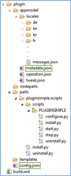
Table 2 provides more details about the files and directories in the plug-in folder. Do not worry if the descriptions in Tables 1 and 2 do not make complete sense yet. They soon will. Some entries are not used in our simple example, so you have a few less things to worry about for now.
Table 2. The plug-in files and directories
| File / Directory | Description |
|---|---|
| appmodel/metadata.json | Defines the plug-in elements - components, links, and policies - and attributes that you want to make available to users in the Virtual Application Builder. |
| appmodel/operation.json | Defines the operations that could be invoked during virtual application runtime. Operations defined in this file will launch actions on a component of a running pattern. We do not use operation.json in our example. |
| appmodel/tweak.json | Defines the configuration parameters that can be changed (tweaked) on a running virtual application. These parameters are the mutable configuration in a running deployment. We do not use tweak.json in our example. |
| nodeparts | This directory contains nodeparts, which are artifacts installed by the activation script on deployed virtual machines generally to augment the OS, or to be used by other parts. The workload agent, which is the component responsible for installing plug-in parts, is a nodepart. Other than the workload agent, which gets installed automatically, we do not use nodeparts in our example. |
| parts | Parts are mostly used to install software on virtual machines. They are groups of files that can be specific to the target machine. The activation script downloads and installs all nodeparts, including the workload agent. The workload agent, in turn, downloads and installs all required parts. |
| templates | Templates map the transformation of the application model to its physical model on the cloud. |
Back to top
Step 4: Update the metadata.json file
The metadata.json file is where you define the components, links, and policies that should be made available to the user in the Virtual Application Builder. When you first create the plug-in project, the generated appmodel/metadata.json file is empty, with just an opening and closing bracket ([ ]). You need to edit the metadata.json file to look like Listing 1.
Listing 1. The updated metadata.json file
[
   {
      "id": "componentSimple1",
      "type": "component",
      "image": "appmodel\/images\/monkey.png",
      "thumbnail": "appmodel\/images\/thumbnail\/monkey.png",
      "label": "componentSimple1",
      "description": "Simple Component 1",
      "attributes": [
         {
            "id": "Name",
            "type": "string",
            "required": false,
            "label": "SampleValue1",
            "description": "Sample Value 1"
         }
      ],
      "category": "application"
   },
   {
      "id": "linkSimple",
      "type": "link",
      "source": [
         "componentSimple1"
      ],
      "target": [
         "componentSimple2"
      ],
      "label": "Simple Link",
      "description": "Simple Link",
      "attributes": [
         {
            "id": "simpleConnector",
            "type": "string",
            "required": false,
            "label": "Simple Connector"
         }
      ]
   },
   {
      "id": "componentSimple2",
      "type": "component",
      "label": "componentSimple2",
      "description": "Simple Component 2",
      "category": "application",
      "image": "appmodel\/images\/banana.png",
      "thumbnail": "appmodel\/images\/thumbnail\/banana.png",
      "attributes": [
         {
            "id": "Name",
            "type": "string",
            "required": false,
            "label": "SampleValue2",
            "description": "Sample Value 2"

         }
      ]
   }
]
There are a few ways in which you can update metadata.json:
- Type and then type some more.
- Cut and paste the code directly from Listing 1 into your workspace.
- Import the file from the patterntypeSimple-1.0.0.0.tgz file, which is included in the Download section of this article.
- Use the Configuration view of the JSON editor to create the entries.
The outer square brackets in Listing 1 indicate that metadata.json is an array of comma-separated JSON objects, each incorporating within its curly braces fields that describe the elements. In this case, we have three metadata elements, respectively called componentSimple1, componentSimple2, and linkSimple. Make a note of their IDs since they must match corresponding package names in the config.json file later. The link object toward the end of the file includes an array of source and target components. This example tells the Virtual Application Builder to show two components and one link, and allow a one-directional link from Simple Component 1 to Simple Component 2, as seen in Figure 5.
Elements and their attributes in the metadata.json file are almost self-explanatory. The image and thumbnail attributes, for example, refer to the images and thumbnails that decorate the components in the Virtual Application Builder. Note that metadata.json in Listing 1 includes references to images that do not yet exist in the appmodel/images folder. You need to import these images from the provided archive at the end of this article, or choose your own. Just make sure the image files for thumbnails are 48 x 48 pixels.
Perhaps the easiest way to import these images into your workspace is through the Configuration view of the JSON editor for metadata.json. In the fields labeled Image and Thumbnail, press Browse… and find the image you wish to import. The system automatically creates theappmodel/images and appmodel/images/thumbnail folders and places the different image files there. For this example, use the same image files (monkey.png and banana.png) for both the images and the thumbnail images. Confirm that the appmodel/images directories were created and that they contain the images you imported.
When done modifying the metadata.json file, press Ctrl+S or choose File > Save from the menu to save your work.
Visual aid for plug-in developers
Notice in Figure 9 the P icon next to the pluginsimple.scripts folder, and the R icon next to the PLUGINSIMPLE folder, as well as some files marked with an asterisk or a checkmark. These types of decorations are visual aids to help plug-in developers identify things easier. Table 3 lists some of the more common decorations.
Table 3. Decorations used in plug-in projects
| Decoration | Description |
|---|---|
| R | Denotes a plug-in role. |
| * | Means it is a standard script for a nodepart or a part. |
| Checkmark | Means it is a role lifecycle script. |
| P | Denotes a plug-in part. |
| N | Denotes a plug-in nodepart. |
The plug-in configuration file
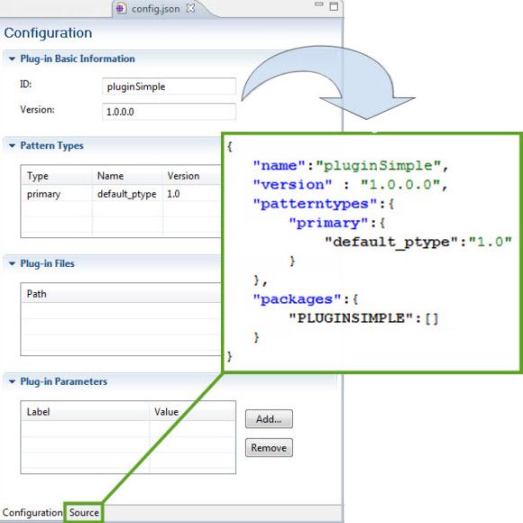
The config.json file, highlighted in Figure 9, is called the plug-in configuration file and it is where you define the relationship between a pattern-type and a plug-in. Figure 10 shows the default config.json file. At least three elements are required: name, version, and patterntypes. Name and version refer to the plug-in's name and version number, while patterntypes refers to the pattern type with which the plug-in is associated.
Figure 10. Configuration and source view of config.json
Back to top
Step 5: Update the generated config.json file
The config.json file needed for this example is slightly more complex than the one generated by default. The next step in this example is to change it to look like Listing 2.
Listing 2. The updated config.json file
{
   "name": "pluginSimple",
   "version": "1.0.0.0",
   "patterntypes": {
      "primary": {
         "patterntypeSimple": "1.0"
      }
   },
   "packages": {
      "componentSimple1Pkg": [
         {
            "persistent": true,
            "requires": {
               "arch": "x86_64",
               "memory": 128
            },
            "parts": [
               {
                  "part": "parts\/componentSimple1.scripts.tgz"
               }
            ]
         }
      ],
      "componentSimple2Pkg": [
         {
            "requires": {
               "arch": "x86_64",
               "memory": 128
            },
            "parts": [
               {
                  "part": "parts\/componentSimple2.scripts.tgz"
               }
            ]
         }
      ],
      "linkSimplePkg": [
         {
            "parts": [
               {
                  "part": "parts\/linkSimple.scripts.tgz"
               }
            ]
         }
      ]
   }
}
Escaped forward slashes in the JSON code
You may be wondering why the forward slashes in Listing 2 are escaped in the strings that contain paths when a single forward slash would do the trick. Using \/ inside a string helps embed JSON code in a <script> HTML tag, which does not permit </ inside a string. It is, therefore, considered good practice to escape forward slashes in JSON code. Some encoding mechanisms, such as PHP's json_encode() method, automatically escape forward slashes. The PDK plug-in does the same for any code it generates.
Back to top
Associating a plug-in with pattern types
The patterntypes element in Listing 2 is where you associate a plug-in with pattern types. A plug-in can be associated with a single primary pattern type as well as one or more secondary pattern types. For a plug-in to be usable, its primary pattern type must be enabled within the Workload Deployer or PureApplication System GUI.
Defining it this way in the config.json file is the easiest way to associate a plug-in with a pattern type. There is also a linked option that provides additional flexibility. If a plug-in declares a linked relationship with a pattern type, it associates that linked pattern type to the plug-in's primary pattern type, which means that when you import the plug-in, any plug-ins associated with the linked pattern type are automatically associated with the plug-in's primary pattern type. For example, assume your config.json file had the following entry:
"patterntypes": {
      "primary": {
         "patterntypeSimple": "1.0"
      },
      "linked": {
         "webapp": "2.0"
      }
   },
All of the plug-ins associated with webapp (the short name for the Web Application Pattern Type 2.0) are also automatically associated with patterntypeSimple. Therefore, when using patterntypeSimple, you would also see the assets of webapp in the Resource Palette. You can also use linked to extend an existing pattern type with additional plugins, without having to change the pattern type itself.
Back to top
Using packages
As the name implies, the packages element allows you to include packages within the plug-in itself. Packages refer to the images, binaries, and attributes necessary to configure a specific role. A role generally refers to a middleware role that a VM plays among the different VMs in the deployed virtual application pattern. For example, DB2®, WebSphere® Application Server, and WebSphere MQ are all roles.
The concept of a role in plug-in development can be a bit confusing at first. For practical purposes, think of a role as the software that gets installed on one or more virtual machines to enable a function - a role if you may - in the deployed pattern. This software is specified in the packages element of the config.json file as a series of nodeparts and parts. Further, the installation and configuration sequence of the software is managed through life cycle scripts mainly to deploy things in the right order in the virtual application pattern. We discuss this topic further below.
A packages element defines the nodeparts and parts that should be bundled with a VM for a particular role. Instead of including the image and binaries directly in the plug-in, you can also reference them from a local or remote location. Our example uses three packages, one for each of the assets that make up the simple plug-in.
Packages that are related to components include a requires element, which identifies specific conditions and constraints that apply to the package. For example, if a package is specific to PureApplication System versus Workload Deployer, the requires element includes an entry such as this:
"products" : ["IPAS"]
Using the requires element allows you to define, among other things, the required architecture, hardware configuration, and operating system for virtual machines that a specific package can be deployed on. For example, the code in Listing 2 specifies that any software included as part of either package can only be installed on a 64-bit OS with a minimum of 128 GB of memory.
Plug-in packages help abstract the OS, hardware, and architectural requirement details from the GUI elements you use in the Virtual Application Builder. The goal is precisely to hide the configuration and deployment details from the person building the Virtual Application Pattern so that he or she can focus on the application itself while Workload Deployer or PureApplication System handles the OS, hardware, and architectural requirements behind the scenes through plug-ins.
Back to top
Using persistent VMs
Besides the requires element in Listing 2, each packages element for components has a persistent attribute set to true. This tells the system to reboot, rather than replace, the virtual machine if it were to stop unexpectedly. Setting this attribute to true is for virtual machines that have recoverable state information, and therefore, it is not really necessary for our example. We put it in there to bring up the point of persistent VMs. The rules of when to use persistent versus non-persistent virtual machines is beyond the scope of this first article. Notice that the linkSimple package does not have a persistent attribute or any architectural requirements because links are mainly used for other purposes.
Back to top
Using parts and nodeparts
The way you bundle a package with your plug-in is through a part or a nodepart. The packages element in the config.json file lets you specify a collection of parts, nodeparts, or both. A part is simply a set of files, generally scripts and binaries, associated with a specific role or dependency. Parts get installed by the workload agent. A nodepart is a set of scripts mainly used to install and configure the OS and base software before parts are deployed. Nodeparts get installed by the activation script. Scripts for both parts and nodeparts are packaged in .tgz files that get bundled with the plug-in. The config.json file in Listing 2 references the parts needed for our example. The next step is to create them.
Back to top
Step 6: Creating parts and nodeparts
To create a part or a nodepart, take the following steps:
- For a part, right-click the plugin/parts folder and select New > Plug-in Part. Similarly for a nodepart, right-click the plugin/nodeparts folder and select New > Plug-in Node Part. Depending on what you choose, the New Plug-in Part or New Plug-in Node Part dialog appears.
- Give the part or nodepart a name, consistent with its entry in the config.json file (without the .tgz extension).
- Choose the script stubs that you want to automatically include with the creation of your part or nodepart. For each entry in this example, choose to create the directory structure as well as the install.py and uninstall.py Python scripts. Figure 11 illustrates the input for the first simple component.
- Create the parts for the config.json file shown in Listing 2. When you build the plug-in later, the PDK creates the corresponding .tgz files for these and includes them in the plug-in .tgz package. Note that for our simple example, we create only parts.
Figure 11. Creating a new plug-in part

Back to top
Using the activation script
When you deploy a virtual application pattern, an activation script in each VM downloads and installs all the nodeparts you have defined for it in your plug-in. Whether you create a nodepart or not, the activation script always downloads an internal nodepart called the workload agent, which is an Open Services Gateway initiative (OSGi) application responsible for installing parts and driving the lifecycle of the roles and dependencies in a plug-in. The activation script downloads and installs all the nodeparts, including the workload agent, and the workload agent, in turn, downloads and installs all the required parts.
Table 4 lists some of the key differences between nodeparts and parts.
Table 4. Comparison between nodeparts and parts
| Nodeparts | Parts |
|---|---|
|
|
| Example: A firewall nodepart that modifies firewall rules before parts are installed. | Example: A WebSphere Application Server. |
Back to top
Using links
Links help establish communication between components. In the Virtual Application Builder, links appear as light blue lines with arrow heads that show the direction of communication. In the case where two components each map to a virtual machine, a link usually opens an inbound and an outbound port from one VM to another or to an external service. By default, all inbound and outbound traffic in a VM is disabled.
Links also provide additional configuration points. For example, in the Virtual Application Builder, you may use a link, such as the User Registry link, to map a role defined in your application to a physical user or group defined in LDAP. This link opens the required firewall ports between the VMs, and also requires you to provide additional configuration information, such as the role name and user or group mapping information.
Back to top
Virtual images vs. virtual appliances
A virtual image is a binary image of a virtual machine, which contains an OS and can also contain middleware and additional applications. Virtual images are normally not self-configurable, which means they do not accept configuration points from the deployment platform (in this case, Workload Deployer or PureApplication System) that allows them to reconfigure the OS or the software based on deployment-specific values. After a virtual image has been deployed, you may have to manually configure the OS or the middleware it is running.
A virtual appliance is a self-configurable virtual image, which means it contains an activation engine - a set of scripts and libraries - that can accept a list of parameters from the deployment platform and use those values to further configure the OS and the bundled software. The VMs that get deployed with Workload Deployer and PureApplication system are virtual images with an activation engine that can run scripts (for example, an activation script) to configure the OS and the software at deployment time.
Note: For legacy reasons, the terms virtual image and virtual appliance are used interchangeably in both Workload Deployer and PureApplication system. This is not a real issue as long as you can distinguish between them. Workload Deployer and PureApplication system work with virtual appliances that are compliant with the Open Virtualization Format (OVF), which is a standard way of packaging and distributing virtual machines.
Back to top
Using roles and life cycle scripts
Recall that a role essentially represents the software that needs to get installed on one or more virtual machines for the VMs to fulfill a role within the deployed virtual application pattern. A VM can have several roles and there can be multiple VMs with the same role.
Because in a pattern the installation and configuration of one VM may depend on another VM, you cannot allow the system to just blindly install all of the parts at once. For each VM, you need to manage the installation and configuration of the software to make sure it is synchronized correctly with the other VMs in the deployed pattern. For example, a WebSphere Application Server role may depend on the configuration of a DB2 role to complete before it can complete its own configuration. This kind of orchestration is done via life cycle scripts, also known as role life cycle scripts. The conductor in this case is the workload agent that gets installed on each VM. After a VM is fully deployed and instantiated, the workload agent begins configuring it for the role it will play in the application.
The install.py and uninstall.py scripts that you optionally create with each part are examples of life cycle scripts. Life cycle scripts mainly use Python for the control logic and leverage maestro scripts and libraries to do most of the infrastructure work. Table 5 provides a brief description of the available life cycle scripts.
Table 5. Life cycle scripts
| Script | Description |
|---|---|
| install.py | Runs only once in the entire lifetime of the VM and does not run again even if the machine is rebooted. A good example of where install.py is useful is to download and install software that needs to be installed on a VM. |
| configure.py | Downloads any artifacts uploaded by the plug-in and configures the software. |
| starts.py | Starts the software, usually a middleware server. |
| stops.py | Stops the software. |
| uninstall.py | Uninstalls the software. |
Roles change their state depending on which lifecycle script is running. In our example, we only worry about three types of scripts: install.py, configure.py, and start.py. Figure 12 shows how these scripts trigger the next role state, assuming a scenario with no errors. If the process terminates with errors, the role moves into a TERMINATED or ERROR state.
You can use the various lifecycle states that a role can assume to resolve dependencies between roles. In other words, the execution of a script supporting one role can be dependent on the lifecycle status change of another role. Lifecycle state changes are used to coordinate the sequence of script executions across the entire pattern (such as across VMs).
Figure 12. Lifecycle scripts triggering role state changes

A life cycle script helps the workload agent coordinate the installation and configuration of the software deployed on a VM. The scripts notify the workload agent of the role's state by setting the maestro.role_status variable. For example:
set maestro.role_status = 'RUNNING'
There is more to say about that, but not in this first part. In Part 2, we will dive deeper into roles and how they help with event notification between VMs. For now, it is enough to allow the script to report to the workload agent that it is in the RUNNING state.
Back to top
Step 7: Create additional roles as needed
When you create the parts for this example, the Eclipse PDK only generates the install.py and uninstall.py life cycle scripts. Since we do not use uninstall.py in our example, you can safely delete it. However, you will need to create the configure.py and start.py scripts. You do this by creating new roles associated with each of the parts.
For each component part (componentSimple1.script and componentSimple2.script), create a new role as follows:
- Right-click inside the Project Explorer window and select New > Plug-in Role.
- Give the role a name consistent with the ID of the component (as entered in the metadata.json file). For our example, the role name for componentSimple1.script is componentSimple1, and the role name for componentSimple2.script is componentSimple2.
- From the dropdown labeled Create in part:, select in which part to create the role.
- Choose to create the directory structure and script stubs for
configure.pyandstart.py. Uncheck all others.
For the link part, create a new role as follows:
- Right-click inside the Project Explorer window and select New > Plug-in Role.
- Give the role a name consistent with the ID of the component (as entered in the metadata.json file). For our example, the role name for linkSimple.script is linkSimple.
- From the dropdown labeled Create in part:, select linkSimple.script.
- Choose to create the directory structure and script stubs for
changed.py.Uncheck all others.
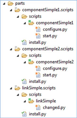
After completing these steps, your directory structure for life cycle scripts looks similar to Figure 13. This assumes you deleted all the instances of uninstall.py.
Figure 13. Lifecycle scripts used in our example
Back to top
Rules and tips for life cycle scripts
The following are rules that every life cycle script must follow:
- All parts must have an
install.pylife cycle script at the root of the .tgz archive file of the scripts. For scripts to be loaded, each component part'sinstall.pyscript must contain the following line:maestro.install_scripts('scripts')This copies the scripts bundled with the plug-in to the workload agent's script directory (scriptdir) and makes them executable so that the agent can start invoking them as part of the deployment.
- Each role's start.py script must notify the workload agent of its status. For example:
maestro.role_status = 'RUNNING'
This tells the system that the software has been installed and is in a RUNNING state.
- A role cannot include a dot(.) character in its name.
- Since the life cycle scripts of different roles get invoked concurrently, make sure you manage them correctly, especially if they share resources or services. To prevent resource conflicts, you can schedule tasks to run certain scripts at specific times, and not in parallel with other role scripts.
- To call a .sh shell script within a life cycle script, always use the method
maestro.trace_call. - In each shell script that you call, use
&to run it as a separate background process, and redirect stdout (1) and stderr (2) to/dev/null(the null device). For example:yourscript.sh 1>2>/dev/null &This prevents any output from stdout or stderr from being displayed.
- Implement as much code as you can in life cycle scripts to avoid dependencies on shell scripts that may be tied to a particular shell or OS.
Back to top
Step 8: Update the generated life cycle scripts
After explaining the rules above, this step will make better sense. For our example to work correctly, we need to add some important missing pieces to the generated life cycle scripts:
Following Rule #1 above
Edit the install.py script of all the parts and, if it is not already provided, at the end of each file (after the logger entry), add the line:
maestro.install_scripts('scripts')
Following Rule #2 above
Edit the start.py script of all the component parts, and at the end of each file (after the logger entry), add the line:
maestro.role_status = 'RUNNING'
You can also log an additional message such as:
Logger.info("componentSimple1 status changed to RUNNING!");
This allows you to see the message in the log files when you are deploying and testing the application.
Finally, modify the changed.py script in the linkSimple component to also log a message:
logger.info("Something has changed!");
Back to top
Transforms and the topology document
So far, you have described the components and link that should appear in the Virtual Application Builder via the appmodel/metadata.json file, as well as the plug-in configuration information for the plug-in via the plugin/config.json file. You have also created the necessary parts and lifecycle scripts for the different roles that we cover in our example. The next step is to tell Workload Deployer or PureApplication System how to transform that metadata or application model into a topology document.
Recall that each package in config.json defines its own set of hardware, OS, and architecture requirements. For each of the packages defined in config.json, you need to specify information that says how to transform that entry into a topology document fragment. You can do this in one of two ways:
- By defining one or more VM templates (.vm files) in the
plugin/templatesdirectory. A vm-template is a virtual machine template. Each .vm file describes how to create a particular VM based on the components, links, and policies defined in the metadata.json file. It can also include requests for other resources such as storage. - By creating Java code that extends specific Kernel services classes, such as TopologyProvider, TopologyProcessor, ServiceProvisioner, and PostProvisioner.
Topology fragments are later combined and resolved into a topology document. It is often recommended to use templates when possible and only use Java code for more complex situations, where a template does not suffice. However, some people may prefer (and recommend) that you directly use Java instead of templates. It becomes a philosophical question. Either way, you eventually end up with Java code because, at runtime, the Apache Velocity engine converts VM templates (also called velocity templates) into Java code. VM templates are simply a convenience for most simple tasks. You can also mix both approaches. For example, one component can use a template-based implementation while another uses a Java-based implementation.
Fortunately, regardless of which implementation method you use, the Eclipse PDK does most of the work in creating transforms for you. All you have to do is create the service components using the New OSGI Service Component wizard. The wizard automatically creates the service components as well as the topology provider for each of the components or links you specify. That is our next step.
Back to top
Step 9: Creating the OSGi service components
To create a new OSGi service component, take the following steps:
- Go to the Project Explorer view and right-click the OSGI-INF folder.
- Select New > OSGI Service Component to bring up the OSGI Service Component wizard.
- In the Name field, enter the ID of the component or link, as specified in the config.json file. The wizard automatically fills the rest of the fields. Notice that the name of the definition file as well as the name of the service declaration .xml file is automatically made lowercase. The field for the component vm-template name is also automatically filled.
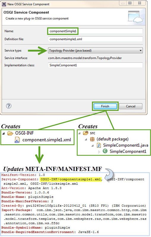
- The Service type dropdown lets you select which type of service to create, in this case whether a template- or Java-based topology provider. Figure 14 illustrates what happens when you choose the template-based implementation, and Figure 15 illustrates what happens when you choose the Java-based implementation.
- Choose the template-based implementation for our example.
- When you click Finish, the new service component is added to the OSGI-INF folder in the plug-in. Any associated template or Java source files get created, and the MANIFEST.MF file is updated automatically.
- For our example, you need to repeat these steps for componentSimple1 and componentSimple2
- For linkSimple, perform the same steps but delete the name that gets automatically filled in the Component vm-template field (linksimple.vm) and copy it over to the Link vm-template field before pressing Finish. This way, the wizard automatically generates a link vm template rather than a component vm template.
Figure 14. Creating the template-based topology document

Figure 15. Creating the Java-based topology
Back to top
OSGi declarative services
OSGi is a specification for creating highly modular Java applications. It allows you to break up a complex Java application into multiple modules and more easily manage cross-dependencies between them. Transform implementations are delivered as OSGi Declarative Services (DS) classes. This allows them to be declarative, meaning they require no explicit code for publishing or consuming services. Instead of having to create explicit Java interfaces and implementations for each component, link, and policy directly, OSGi allows you to declare in an XML file the corresponding implementation classes and interfaces necessary for performing the topology transformation.
OSGi provides many other benefits to Java. All major Java application server vendors today have adopted OSGi, and many complex applications, such as Eclipse, embed OSGi technology in their core engine. If you are interested, see the OSGi web site.
Reviewing the service declaration files
Listings 3 and 4 show the generated service declaration files for both the template-based and Java-based implementations of the first component (componentSimple1). We include the Java-based implementation of the first component to highlight a few things, but remember that you only need one type of implementation per component or link, and, for this example, that is the template-based one.
If you compare Listings 3 and 4, you notice that the template-based implementation still uses an implementation class that extends TopologyProvider. The difference is that for the Java-based implementation, you supply your own Java class that extends TopologyProvider (see the class ComponentSimple1 in Listing 5 as an example), whereas the template-based implementation gets converted to a Java class that extends TopologyProvider based on the generated VM template files. The Java code creates a topology.json output, using a JSON4J type library that dynamically creates JSON elements. Part 2 of this series covers this topic in more detail.
Listing 3. The template-based componentsimple1.xml file
<?xml version="1.0" encoding="UTF-8"?>
<scr:component xmlns:scr="http://www.osgi.org/xmlns/scr/v1.1.0"
 name="componentSimple1">;
  <implementation class="com.ibm.maestro.model.transform.template.
   TemplateTransformer" />;
  <service>
   <provide interface="com.ibm.maestro.model.transform.TopologyProvider" />
  </service>
  <property name="component.template" type="String" value="templates/
   componentsimple1.vm" />
</scr:component>
Listing 4. The Java-based componentsimple1.xml file
<?xml version="1.0" encoding="UTF-8"?>
<scr:component xmlns:scr="http://www.osgi.org/xmlns/scr/v1.1.0"
  name="componentSimple1">;
	<implementation class="SimpleComponent1" />;
	<service>
		<provide interface="com.ibm.maestro.model.transform.TopologyProvider" />
	</service>
</scr:component>
Listing 5. The Java-based implementation skeleton
package default;

import com.ibm.json.java.JSONObject;
import com.ibm.maestro.model.transform.TopologyProvider;

public class ComponentSimple1 extends TopologyProvider {

	/**
     * Transforms a component from the application model into objects for the topology
     * document.
     *
     * @param vmTemplateNamePrefix
     *            Prefix for the vm-template name. Ensures uniqueness in the topology
     *            document; transforms may append arbitrary strings.
     * @param applicationUrl
     *            URL of the root of the application artifacts (within the storehouse).
     * @param applicationComponent
     *            Component object from the application model.
     * @param transformer
     *            TODO
     * @return Partial topology document containing objects created for the component.
     * @throws Exception
     *             Terminates the transformation process with an error.
     */
	@Override
	public JSONObject transformComponent(String prefix, String applicationUrl,
			JSONObject component, com.ibm.maestro.model.transform.Transformer
            transformer) throws Exception {
		//TODO: implement your component transform logic
		return new JSONObject();
	}

	/**
     * Transforms a link from the application model by updating the partial
     * topology documents associated with the source and target components.
     * Note that all component transforms are run before the link transforms.
     *
     * @param sourceFragment
     *            Partial topology document associated with the source component.
     * @param targetFragment
     *            Partial topology document associated with the target component.
     * @param applicationUrl
     *            URL of the root of the application artifacts (within the storehouse).
     * @param applicationLink
     *            Link object from the application model.
     * @param transformer
     *            TODO
     * @throws Exception
     *             Terminates the transformation process with an error.
     */
	@Override
	public void transformLink(JSONObject sourceFragment, JSONObject targetFragment,
     String applicationUrl,
		JSONObject link, com.ibm.maestro.model.transform.Transformer transformer)
         throws Exception {
		//TODO: Implement your link transform logic
	}
}
Back to top
Step 10: Update the velocity templates
When you create the OSGi service components for our example, the tool generates default velocity templates (.vm files) and places them in the plug-in/templates folder. If you correctly created the OSGi service components, your MANIFEST.MF file has been updated to point to the .xml files in Listings 3 and 4, as illustrated in Figure 14 and Figure 15, and your plug-in/templates folder has three files: componentsimple1.vm,componentsimple2.vm, and linksimple.vm. The next step is to update those files to match the components in our example. Listings 6 through 8 show what they look like. Update them accordingly.
Listing 6. The updated componentsimple1.vm file
{
    "vm-templates": [
        {
            "persistent":false,
            "name": "componentSimple1",
            "roles": [
                {
                    "parms": {

                    },
                    "type": "componentSimple1",
                    "name": "componentSimple1"
                }
            ],
            "packages": [
                "componentSimple1Pkg"
            ]
        }
    ]
}
Listing 7. The updated componentsimple2.vm file
{
    "vm-templates": [
        {
            "persistent":false,
            "name": "componentSimple2",
            "roles": [
                {
                    "parms": {

                    },
                    "type": "componentSimple2",
                    "name": "componentSimple2"
                }
            ],
            "packages": [
                "componentSimple2Pkg"
            ]
        }
    ]
}
Listing 8. The updated linksimple.vm file
#set( $sourceRole     = "componentSimple1" )  ## sourceRole
 value used after template rendered
#set( $sourcePackages = ["linkSimplePkg"] )  ## sourcePackages
 value used after template rendered
#set( $source = $provider.getMatchedRole( $sourceFragment, $sourceRole ) )
#set( $targetRole  = "componentSimple2" )
#set( $target = $provider.getMatchedRole( $targetFragment, $targetRole ) )
#if ( $target )
      #set( $roleType    = "banana" )
      #set( $dependsRole = "${target.template.name}.$target.role.name" )
#end


[
    {
        "role"        : "$dependsRole",
        "type"        : "$roleType",

    }
]
You can link components to introduce dependencies between roles that are associated with each component. These dependencies are defined in the transformation document of the link and show which role is dependent on the other, and what parameters are passed between them using a role depends element. During the deployment, these dependencies are used to process and synchronize the application.
Back to top
Step 11: Building the pattern type and plug-in
To build a pattern type, you simply right click its project and select IBM Workload Plug-in > Build. This also builds any associated plug-ins. During the build, the console window displays the different build operations and eventually concludes with either a "BUILD SUCCESSFUL" or BUILD FAILED" message. If the build is successful, refresh your project to see a created export directory as shown in Figure 16. The .tgz files are what you need to import into Workload Deployer or PureApplication system.
Figure 16. The generated export file after building a pattern type

You can also build the plug-in project independently in the same way. Right click the plug-in project and select IBM Workload Plug-in > Build.
Back to top
Deploying your work directly into Workload Deployer or PureApplication System
If you have the right access, you can deploy your work directly from Eclipse into Workload Deployer or PureApplication System. To do this, first you must configure the information necessary to communicate with the deployer. Go to Windows > Preferences and choose IBM Workload Plug-in to bring up the IBM Workload Plug-in window as seen in Figure 17.
Figure 17. IBM Workload Plug-in preferences window
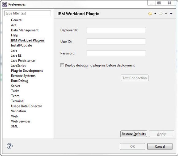
Test your connection and make sure it is successful before applying the changes.
Once you have done this, you can right-click a pattern type or plug-in project and choose IBM Workload Plug-in > Install/update to deployer to directly update the Workload Deployer or PureApplication System with your pattern type and plug-in. Similarly, you can choose IBM Workload Plug-in > Remove from deployer to delete pattern types and plug-ins from the deployer. Remember that to add or delete a plug-in, its associated pattern type must be enabled. If you get an HTTP Response code 403 (Access Forbidden), it means you cannot use this method. You have to manually export the file and import it into Workload Deployer.
Back to top
Step 12: Manually exporting and importing the pattern type and plug-in
Exporting
After successfully building a pattern type or plug-in from Eclipse to manually export it, perform the following steps:
- Right-click the corresponding project (pattern type or plug-in) and select Export.
- In the Export dialog, select General > File System and press Next.
- Specify the .tgz package under export directory and the location where the system should place the exported file. Click Finish.
Importing
Within Workload Deployer or PureApplication System, go to the Cloud > Pattern Types menu to import the .tgz file you exported earlier corresponding to the Simple pattern type, as illustrated in Figure 18. Importing the pattern type automatically imports the associated plug-in. Once you import the pattern, you must enable it. You also have the option of importing a plug-in independently. To do this, you must navigate to Cloud > System Plug-ins, and click the + icon on the toolbar to add the new plug-in and browse to the corresponding .tgz file.
Figure 18. Importing and enabling a pattern type

Back to top
Using the plug-in to create and deploy a virtual application
You are now ready to create and deploy a virtual application instance based on the pattern type and plug-in you created:
- Review Figure 1, Figure 2, and Figure 5 and navigate to Patterns > Virtual Applications to create a new virtual application instance based on the pattern type "patterntype.Simple 1.0".
- Within the Virtual Application Builder, drag the simple components that now appear in the Resource Palette onto the canvas and make your virtual application pattern look like Figure 5.
- Save your work, giving your new pattern a name.
- Exit the Virtual Application Builder.
- Find your new Virtual Application Pattern under Patterns > Virtual Application and select Deploy.
- In the Deploy Virtual Application window, leave the default values as is and press Ok to begin the deployment.
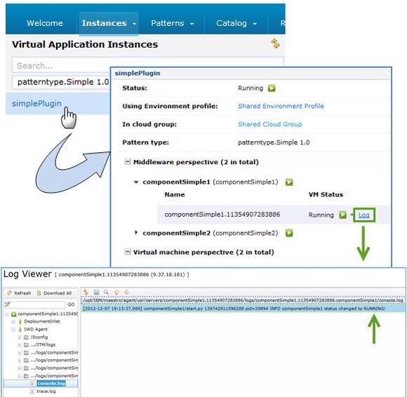
- During deployment and activation, you can inspect the VM instances created and their state by navigating to Instances > Virtual Application Instances. You can also review the logs to make sure the system invoked the different lifecycle scripts in your plug-in. Figure 19 shows an example.
Figure 19. Reviewing the logs
Back to top
Conclusion
This concludes our introduction to creating plug-ins for use in virtual application patterns. With these essential concepts, you are on your way to explore more complex examples. Part 2 will dive deeper into the topic of plug-ins by walking you through a more complex example.
Acknowledgements
The authors would like to thank Andre Tost for his insights and suggestions during his review of this article.