实训周实验(eNSP安装+简单使用+实验项目)总结
本学期末的实训也结束了,相应地本学期结束了,本周实训深度学习了OSI七层模型里的一些协议,以及几个网络拓扑的搭建和使用命令。
eNSP里用的是华为模拟机,但是这学期开的课用的是H3C教材,老师说H3和华为本是出自一家,但是机器的命令还是有很多地方不同。
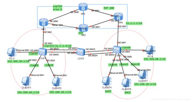
以下,是实训总实验拓扑结构
实验要求如下:
实验要求:
一、address
1.每台设备需要配置LOOP 0地址作为标识(例如:1.1.1.1、2.2.2.)掩码为32位,接口地址配置为24位的掩码。
2.SW2为DHCP-server,要求为PC4/PC5动态配置地址,要求使用接口地址池方式分配,网段地址为192.168.45.0/24,dns-list:100.1.1.1 lease:2 exclude-address: 192.168.45.1-192.168.45.10
二、广域网技术
1.R1与R3之间使用ppp链路,要求两台路由器使用CHAP认证,使用双向认证,用户名为jisuanji,密码使用密文为huawei@123。
三、Switching
1.在交换机上创建相关VLAN,分别为10/20/30/45/60;
2.为增加链路带宽及实现链路负载,配置链路聚合SW3分别于SW1/SW2使用LACP-static方式。
3.交换机互联的接口配置Trunk,且允许相关vlan通过,
4.配置RSTP协议,要求所有access接口都能够快速收敛。
5.将PC3/PC6的接口的BPDU过滤掉。
四、VLAN间技术
1.SW2与R4之间使用VLANIF技术
2.SW1与R1之间使用单臂路由技术,SW1允许要允许相应Vlan通过,R1要创建相应子接口。
五、Routing
1.R1/R2/R3/SW1运行OSPF进程号为10,相连的接口都属于区域0(如图)并且使用LOOP 0接口作为OSPF router-id,要求路由可达,R1/R2与R1/SW1为保证网络安全性,
需配置OSPF的接口认证,用户名huawei,密码huawei@123.
2. R2/R3/R4运行RIP进程号为100,使用V2版本,取消自动聚合,R2和R3属于性能比较低路由器,要求R4发布路由时使用手动聚合,为保证数据安全性,需配置Rip
V2密文认证,用户名huawei,密码huawei@123.
3.在R2/R3路由器上ospf和RIP进行互相引入,为防止环路使用打tag。
4.要求PC-3能够访问PC-6,且通过ISP访问。
六、远程访问功能
1.为确保网络网络设备的正常运行,网络工程师希望可以远程管理设备,需要在SW1、SW2开启Telnet服务,用户名为gongshang,密码为gongshang@123,权限为15.
七、PING
1.要求PC1与PC2能够互访,可以适当创建三层接口。
2.要求PC1/PC2都能访问到PC4/PC5,且通过ISP访问。
3.要求PC2能够访问到PC7,通过二层网络访问。
先放一下eNSP的安装包
百度云链接
提取码:bbjy
原实验拓扑以及要求
提取码:jhji
安装步骤很简单,跟着系统提示走就可以了,但是要注意一点Wireshark和Oracle VM VirtualBox也都要安装才能使用。
打开网络拓扑结构前要先注册设备:右上角菜单->工具->注册设备
以前的版本只有上面三个选项,新版有五个,前三个一定要勾上,然后点注册,直到注册成功。
所有的实验做完之后,保存步骤为:
先在所有的设备中 save之前的设置。
然后关闭设备->保存
点叉号关闭eNSP的时候也要点“是”保存拓扑。
下面开始我们的实验步骤:
1.启动每台设备,更改每个设备的名字为R1,R2,R3,R4,SW1,SW2,SW3
[Huawei]sysname SW1
对每个机器更改名字。
2.配置PC3,CLIENT1,CLIENT2,CLIENT7,PC6主机的ip地址与网关(网关以最后八位为254)
因为4和5要做DHCP,所以暂且不配。
3.先看实验目标,第三个要求为:要求PC2能够访问到PC7,通过二层网络访问,此时用不到上面四个路由器,所以先来做第三个目标要求,根据以上要求可以知道,在LSW1上要做VLAN划分,SW2上做VLANIF,并且之间连接的接口要做链路聚合。同时,主机3和主机6的BPDU报文要过滤掉,并且与主机相连的接口设置为边缘端口。
SW1上的命令:
[SW1]stp enable
[SW1]stp mode rstp
[SW1]vlan batch 10 20 30
[SW1]int g 0/0/2
[SW1-GigabitEthernet0/0/2]port link-type access
[SW1-GigabitEthernet0/0/2]port default vlan 10
[SW1-GigabitEthernet0/0/2]stp edged-port enable
[SW1]int g 0/0/3
[SW1-GigabitEthernet0/0/3]port link-type access
[SW1-GigabitEthernet0/0/3]port default vlan 20
[SW1-GigabitEthernet0/0/3]stp edged-port enable
[SW1]int g 0/0/4
[SW1-GigabitEthernet0/0/4]port link-type access
[SW1-GigabitEthernet0/0/4]port default vlan 30
[SW1-GigabitEthernet0/0/4]bpdu disable
[SW1-GigabitEthernet0/0/4]stp edged-port enable
[SW1]int Eth-Trunk 1
[SW1-Eth-Trunk1]port link-type trunk
[SW1-Eth-Trunk1]port trunk allow-pass vlan 20
[SW1-Eth-Trunk1]mode lacp-static
[SW1-Eth-Trunk1]trunkport GigabitEthernet 0/0/20 to 0/0/21
SW3的命令
[SW3]stp enable
[SW3]stp mode rstp
[SW3]vlan batch 20
[SW3]int Eth-Trunk 1
[SW3-Eth-Trunk1]port link-type trunk
[SW3-Eth-Trunk1]port trunk allow-pass vlan 20
[SW3-Eth-Trunk1]mode lacp-static
[SW3-Eth-Trunk1]trunkport GigabitEthernet 0/0/20 to 0/0/21
[SW3]int Eth-Trunk 2
[SW3-Eth-Trunk2]port link-type trunk
[SW3-Eth-Trunk2]port trunk allow-pass vlan 20
[SW3-Eth-Trunk2]mode lacp-static
[SW3-Eth-Trunk2]trunkport GigabitEthernet 0/0/23 to 0/0/24
SW2的命令
[SW2]stp enable
[SW2]stp mode rstp
[SW2]int Eth-Trunk 1
[SW2-Eth-Trunk1]port link-type trunk
[SW2-Eth-Trunk1]port trunk allow-pass vlan 20
[SW2-Eth-Trunk1]mode lacp-static
[SW2-Eth-Trunk1]trunkport GigabitEthernet 0/0/23 to 0/0/24
[SW2]vlan batch 20 45 60
[SW2]interface Vlanif 20
[SW2-Vlanif20]ip add 192.168.20.254 24
[SW2]int g 0/0/5
[SW2-GigabitEthernet0/0/5]port link-type access
[SW2-GigabitEthernet0/0/5]port default vlan 20
[SW2-GigabitEthernet0/0/5]stp edged-port enable
[SW2]int g 0/0/4
[SW2-GigabitEthernet0/0/4]bpdu disable
这时候在CLIENT7上ping一下CLIENT2,可以ping通~
2ping7也可以ping通
(这里有个注意事项:可能是我的电脑问题,内存才4G,所以信号会不稳定,第一次做这个实验的时候,2去ping7是不通的,但是7ping2可以通,然后2ping7才可以通,用机房里的机器就不会出现这个问题。所以当2ping7不通的时候,可以7ping2试一试)
4.这时候SW1上除了单臂路由还未配置外,SW2还剩下几个VLANIF和DHCP没有配置,命令如下
SW2:
[SW2]int Vlanif 60
[SW2-Vlanif60]ip add 192.168.60.254 24
[SW2]int g 0/0/4
[SW2-GigabitEthernet0/0/4]port link-type access
[SW2-GigabitEthernet0/0/4]port default vlan 60
[SW2-GigabitEthernet0/0/4]stp edged-port enable
[SW2]int g 0/0/2
[SW2-GigabitEthernet0/0/2]port link-type access
[SW2-GigabitEthernet0/0/2]port default vlan 45
[SW2-GigabitEthernet0/0/2]stp edged-port enable
[SW2]int g 0/0/3
[SW2-GigabitEthernet0/0/3]port link-type access
[SW2-GigabitEthernet0/0/3]port default vlan 45
[SW2-GigabitEthernet0/0/3]stp edged-port enable
[SW2]dhcp enable
[SW2]int Vlanif 45
[SW2-Vlanif45]ip add 192.168.45.254 24
[SW2-Vlanif45]dhcp select interface
[SW2-Vlanif45]dhcp server dns-list 100.1.1.1
[SW2-Vlanif45]dhcp server excluded-ip-address 192.168.45.1 192.168.45.10
[SW2-Vlanif45]dhcp server lease day 2
配置好DHCP后,可以在CLIENT2和3的命令行里输入 ipconfig 看一看是否已经自动分配了ip地址
成功。
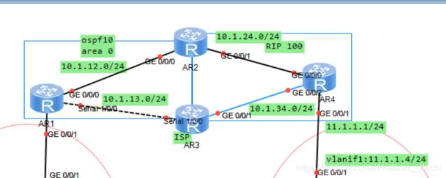
5.下面的网络配置好之后,那么开始配置上面四个路由器,因为实验项目没给网段,所以,我自己给分配了一下网段,如下。
配置过程:配置ip地址,ospf协议,宣告网络,rip协议,宣告网络,双向引入,打tag标记
命令如下:
R1
[R1]int g 0/0/0
[R1-GigabitEthernet0/0/0]ip add 10.1.12.1 24
[R1]int se 1/0/0
[R1-Serial1/0/0]ip add 10.1.13.1 24
[R1]int LoopBack 0
[R1-LoopBack0]ip add 1.1.1.1 32
[R1-LoopBack0]ospf 10
[R1-ospf-10]area 0.0.0.0
[R1-ospf-10-area-0.0.0.0]network 1.1.1.1 0.0.0.0
[R1-ospf-10-area-0.0.0.0]network 10.1.12.0 0.0.0.255
[R1-ospf-10-area-0.0.0.0]network 10.1.13.0 0.0.0.255
R2
[R2]int g 0/0/0
[R2-GigabitEthernet0/0/0]ip add 10.1.12.2 24
[R2]int g 0/0/1
[R2-GigabitEthernet0/0/1]ip add 10.1.24.2
[R2]int LoopBack 0
[R2-LoopBack0]ip add 2.2.2.2 32
[R2]ospf 10
[R2-ospf-10]area 0.0.0.0
[R2-ospf-10-area-0.0.0.0]network 2.2.2.2 0.0.0.0
[R2-ospf-10-area-0.0.0.0]network 10.1.12.0 0.0.0.255
[R2]rip 100
[R2-rip-100]version 2
[R2-rip-100]undo summary
[R2-rip-100]network 10.0.0.0
[R2]ospf 10
[R2-ospf-10]import-route rip 100 route-policy ospf2rip
[R2]rip 100
[R2-rip-100]import-route ospf 10 route-policy rip2ospf
//双向引入
[R2]ospf 10
[R2-ospf-10] import-route rip 100 route-policy ospf2rip
[R2-ospf-10]q
[R2]rip 100
[R2-rip-100] import-route ospf 10 route-policy rip2ospf
[R2-rip-100]q
//打标签
[R2]route-policy ospf2rip deny node 10
[R2-route-policy]if-match tag 100
[R2]route-policy ospf2rip permit node 20
[R2-route-policy]apply tag 200
[R2]route-policy rip2ospf deny node 10
[R2-route-policy]if-match tag 300
[R2]route-policy rip2ospf permit node 20
[R2-route-policy]apply tag 400
R3
[R3]int se 1/0/0
[R3-Serial1/0/0]ip add 10.1.13.3 24
[R3]int g 0/0/1
[R3-GigabitEthernet0/0/1]ip add 10.1.34.3 24
[R3]int LoopBack 0
[R3-LoopBack0]ip add 3.3.3.3 32
[R3]ospf 10
[R3-ospf-10]area 0.0.0.0
[R3-ospf-10-area-0.0.0.0]network 3.3.3.3 0.0.0.0
[R3-ospf-10-area-0.0.0.0]network 10.1.13.0 0.0.0.255
[R3]rip 100
[R3-rip-100]version 2
[R3-rip-100]undo summary
[R3-rip-100]network 10.0.0.0
//双向引入
[R3]ospf 10
[R3-ospf-10] import-route rip 100 route-policy ospf2rip
[R3]rip 100
[R3-rip-100] import-route ospf 10 route-policy rip2ospf
//打标签
[R3]route-policy rip2ospf deny node 10
[R3-route-policy] if-match tag 200
[R3]route-policy rip2ospf permit node 20
[R3-route-policy] apply tag 100
[R3]route-policy ospf2rip deny node 10
[R3-route-policy] if-match tag 400
[R3]route-policy ospf2rip permit node 20
[R3-route-policy] apply tag 300
R4
[R4]int LoopBack 0
[R4-LoopBack0]ip add 4.4.4.4 32
[R4]int g 0/0/0
[R4-GigabitEthernet0/0/0]ip add 10.1.24.4 24
[R4-GigabitEthernet0/0/0]quit
[R4]int g 0/0/2
[R4-GigabitEthernet0/0/2]ip add 10.1.34.4 24
[R4-GigabitEthernet0/0/2]q
[R4]int g 0/0/1
[R4-GigabitEthernet0/0/1]ip add 11.1.1.1 24
[R4-GigabitEthernet0/0/1]quit
[R4]rip 100
[R4-rip-100]version 2
[R4-rip-100]undo summary
[R4-rip-100]network 4.0.0.0
[R4-rip-100]network 10.0.0.0
[R4-rip-100]network 11.0.0.0
测试一下是否成功,在R1上ping一下R4 4.4.4.4
成功。
6.下一步,我们要使左下角部分的部分主机能够ping同上面的路由器部分,并且还要满足CLIENT1 CLIENT2能够互相ping通。即在R1和SW1做单臂路由。
命令如下
R1:在接口0/0/1创建子接口
[R1]int g 0/0/1.1
[R1-GigabitEthernet0/0/1.1]ip add 192.168.10.254 24
[R1-GigabitEthernet0/0/1.1]dot1q termination vid 10
[R1-GigabitEthernet0/0/1.1]arp broadcast enable
[R1]int g 0/0/1.2
[R1-GigabitEthernet0/0/1.2]ip add 192.168.20.254 24
[R1-GigabitEthernet0/0/1.2]dot1q termination vid 20
[R1-GigabitEthernet0/0/1.2]arp broadcast enable
[R1]int g 0/0/1.3
[R1-GigabitEthernet0/0/1.3]ip add 192.168.30.254 24
[R1-GigabitEthernet0/0/1.33]dot1q termination vid 30
[R1-GigabitEthernet0/0/1.33]arp broadcast enable
宣告网络:
[R1]ospf 10
[R1-ospf-10]area 0.0.0.0
[R1-ospf-10-area-0.0.0.0]network 192.168.10.0 0.0.0.255
[R1-ospf-10-area-0.0.0.0]network 192.168.20.0 0.0.0.255
[R1-ospf-10-area-0.0.0.0]network 192.168.30.0 0.0.0.255
SW1:
[SW1]int g 0/0/1
[SW1-GigabitEthernet0/0/1]port link-type trunk
[SW1-GigabitEthernet0/0/1]port trunk allow-pass vlan 10 20 30
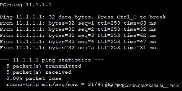
此时在PC3上ping一下R4的 11.1.1.1网络接口看是否可达(CLIENT1和2也应该可达)
成功。
7.此时只需要做最后一步,然后左下角就可以和右下角的主机能够ping通。
在SW2和R4之间建立连接
在之前的步骤中,vlan20,45,60的ip地址已经设置,还剩下默认vlan1的ip地址没有配置,配置好ip地址后,同时在rip中宣告网络
(注意这里rip版本要一致)
命令如下:
SW2:
[SW2]int Vlanif 1
[SW2-Vlanif1]ip add 11.1.1.4 24
[SW2]rip 100
[SW2-rip-100]v 2
[SW2-rip-100]undo sum
[SW2-rip-100]network 11.0.0.0
[SW2-rip-100]network 192.168.20.0
[SW2-rip-100]network 192.168.45.0
[SW2-rip-100]network 192.168.60.0
[SW2]int g 0/0/1
[SW2-GigabitEthernet0/0/1]port link-type trunk
[SW2-GigabitEthernet0/0/1]port trunk allow-pass vlan 20 45 60
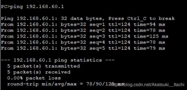
这时候测试一下网络是否可达,在PC3ping一下PC6
成功。
这时候,实验基本就已经完成了,不过还有几个要求没做。
8.R1和R3之间做chap双向验证
R1为主验证方,R3为被验证方
[R1]int se 1/0/0
[R1-Serial1/0/0]link-protocol ppp
[R1-Serial1/0/0]pp authentication-mode chap
[R1]aaa
[R1-aaa]local-user jisuanji password cipher huawei@123
[R1-aaa]local-user jisuanji service-type ppp
[R3]int se 1/0/0
[R3-Serial1/0/0]link-protocol ppp
[R3-Serial1/0/0]ppp chap user jisuanji
[R3-Serial1/0/0]ppp chap password cipher huawei@123
R3为主验证方,R1为被验证方
[R3]int se 1/0/0
[R3-Serial1/0/0]link-protocol ppp
[R3-Serial1/0/0]ppp authentication-mode chap
[R3]aaa
[R3-aaa]local-user jisuanji password cipher huawei@123
[R3-aaa]local-user jisuanji service-type ppp
[R1]int se 1/0/0
[R1-Serial1/0/0]ppp chap user jisuanji
[R1-Serial1/0/0]ppp chap password cipher huawei@123
9.R1和R2之间做ospf密文验证
命令如下:
[R1]int g 0/0/0
[R1-GigabitEthernet0/0/0]ospf authentication-mode md5 1 cipher huawei@123
[R2]int g 0/0/0
[R2-GigabitEthernet0/0/0]ospf authentication-mode md5 1 cipher huawei@123
10.R2,R3,R4之间做rip密文验证
[R2]int g 0/0/1
[R2-GigabitEthernet0/0/1]rip authentication-mode md5 usual cipher huawei@123
[R3]int g 0/0/1
[R3-GigabitEthernet0/0/1]rip authentication-mode md5 usual cipher huawei@123
[R4]int g0/0/0
[R4-GigabitEthernet0/0/0]rip authentication-mode md5 usual cipher huawei@123
[R4]int g 0/0/2
[R4-GigabitEthernet0/0/2]rip authentication-mode md5 usual cipher huawei@123
11.在SW1和SW2上做TELNET服务
SW1:
[SW1]telnet server enable
[SW1]user-interface vty 0 4
[SW1-ui-vty0-4]authentication-mode aaa
[SW1-ui-vty0-4]protocol inbound telnet (这条命令在虚拟机是默认打开的,但是在真机中默认是不打开的)
[SW1]aaa
[SW1-aaa]local-user gongshang password cipher gongshang@123
[SW1-aaa]local-user gongshang privilege level 15
[SW1-aaa]local-user gongshang service-type telnet
SW2:
[SW2]telnet server enable
[SW2]user-interface vty 0 4
[SW2-ui-vty0-4]authentication-mode aaa
[SW2-ui-vty0-4]protocol inbound telnet
[SW2]aaa
[SW2-aaa]local-user gongshang password cipher gongshang@123
[SW2-aaa]local-user gongshang privilege level 15
[SW2-aaa]local-user gongshang service-type telnet
配置完以后,可以在用户视图下 键入命令 telnet 127.0.0.1 测试是否成功。
所有配置完毕后,可以按照实验要求七对主机互ping一下,看看是否能ping通。
华丽的分割线。
以上就是这次实验的基本步骤,今天又重新边写边做了一遍。
下面说一下在实训过程中遇到的无数些坑以及帮同学看拓扑的时候一些常见的错误!
1.左下角的主机ping不通上方的路由器R1-R4
错误的可能原因:
单臂路由配置的不正确。
连接主机的接口没有设置默认VLAN和链路类型为access
连接路由器的接口没有设置允许VLAN 10 20 30通过和链路类型为trunk
路由器R1没有宣告主机的网段
2.R1和R4无法互通
这里可以键入命令 dis ip routing-table 来查看路由信息
错误的可能原因有:
双向引入以及tag标签的打入有问题
没有宣告网络
3.路由器R1-R4无法与右下角的主机互通
错误的可能原因有:
R4和SW2没有宣告11.0.0.0的网络(注意,RIP宣告的是有类网段)
SW2没有宣告20 45 60的网络
R4和SW2之间rip的版本不一致
4.PC2和PC7通过二层网络不能互访
错误的原因可能有:
LSW3要没有创建VLAN20
LSW3的eth trunk 在两端的接口一致,也就是说正确应该为20和21接口应该为eth trunk x,23和24接口应该为 eth trunk y 且x!=y
LSW1和LSW2之间的所有接口没有设置为trunk
(注意,LSW1和LSW3或者LSW2和LSW3之间的eth trunk 可以不同)
暂时想到的问题就这么多了。
要放假啦~~~(虽然要准备考研...苦)


