几何变换
几何变换详解
在三维图形学中,几何变换大致分为三种,平移变换(Translation),缩放变换(Scaling),旋转变换(Rotation)。以下讨论皆针对DirectX,所以使用左手坐标系。
平移变换
将三维空间中的一个点[x, y, z, 1]移动到另外一个点[x’, y’, z’, 1],三个坐标轴的移动分量分别为dx=Tx, dy=Ty, dz=Tz, 即
x’ = x + Tx
y’ = y + Ty
z’ = z + Tz
缩放变换
将模型放大或者缩小,本质也是对模型上每个顶点进行放大和缩小(顶点坐标值变大或变小),假设变换前的点是[x, y, z, 1],变换后的点是[x’, y’, z’, 1],那么
x’ = x * Sx
y’ = y * Sy
z’ = z * Sz
旋转变换
这是三种变换中最复杂的变换,这里只讨论最简单的情况,绕坐标轴旋转,关于绕任意轴旋转,在后续的随笔中介绍。
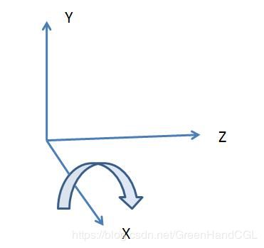
绕X轴旋转时,顶点的x坐标不发生变化,y坐标和z坐标绕X轴旋转θ度,旋转的正方向为顺时针方向(沿着旋转轴负方向向原点看)。[x, y, z, 1]表示变换前的点,[x’, y’, z’, 1]表示变换后的点。变换矩阵如下。关于旋转的正方向,OpenGL与多数图形学书籍规定旋转正方向为逆时针方向(沿着坐标轴负方向向原点看),比如Computer Graphics C Version,p409。

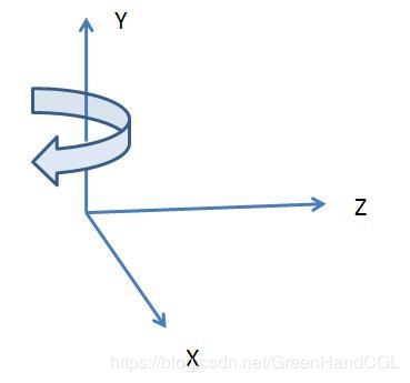
绕Y轴旋转

绕Y轴旋转时,顶点的y坐标不发生变化,x坐标和z坐标绕Y轴旋转θ度。[x, y, z, 1]表示变换前的点,[x’, y’, z’, 1]表示变换后的点。变换矩阵如下。

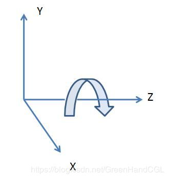
绕Z轴旋转

绕Z轴旋转时,顶点的z坐标不发生变化,x坐标和y坐标绕Z轴旋转θ度。[x, y, z, 1]表示变换前的点,[x’, y’, z’, 1]表示变换后的点。变换矩阵如下。

绕坐标轴旋转的矩阵推导
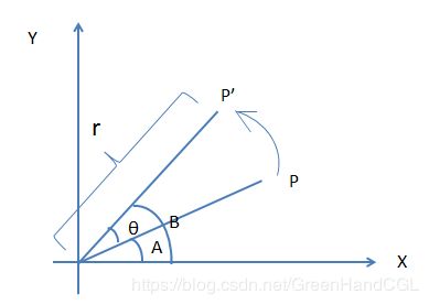
上面三个旋转矩阵是如何得来的呢?我们推导一下,首先看一下二维的情况,再扩展到三维即可。实际上上面三种绕坐标轴旋转的情况属于特殊的二维旋转,比如绕Z轴旋转,相当于在与XOY平面上绕原点做二维旋转。
假设点P(x, y)是平面直角坐标系内一点,其到原点的距离为r,其与X轴的夹角为A,现将点P绕原点旋转θ度,得到点P’(x’, y’),P’与X轴的夹角为B,则A = B - θ。(注意,在二维坐标中,逆时针旋转时角度为正,顺时针旋转时角度为负,下图中由P旋转到P’,角度为θ,若是由P’转到P,则角度为-θ)。
![]()
![]()
![]()
![]()
于是可得下面的转换方程
由于这里使用齐次坐标,所以还需加上一维,最终变成如下形式(绕Z轴旋转矩阵)

和前面给出的绕Z轴旋转矩阵完全吻合。
对于绕X轴旋转的情况,我们只需将式一中的x用y替换,y用z替换,z用x替换即可。替换后得到
 (式二)
(式二)
对应的旋转矩阵为(绕X轴旋转矩阵):

对于绕Y轴旋转的情况,只需对式二做一次同样的替换即可,的到的变换方程为

对应的变换矩阵为(绕Y轴旋转矩阵):

逆矩阵
平移变换矩阵的逆矩阵与原来的平移量相同,但是方向相反。

旋转变换矩阵的逆矩阵与原来的旋转轴相同但是角度相反。


缩放变换的逆矩阵正好和原来的效果相反,如果原来是放大,则逆矩阵是缩小,如果原来是缩小,则逆矩阵是放大。

作者:zdd
出处:http://www.cnblogs.com/graphics/
动动小手
#include "rotate.h"

bool rotate_Z(pcl::PointCloud<pcl::PointXYZ>::Ptr cloud, pcl::PointCloud<pcl::PointXYZ>::Ptr cloud_rotated, float theta)
{
	/* Reminder: how transformation matrices work :
	|-------> This column is the translation
	| cos(theta) -sin(theta) 0 x |  \
	| sin(theta)  cos(theta) 0 y |   }-> The identity 3x3 matrix (Z axis) on the left
	| 0           0          1 z |  /
	| 0           0          0 1 |    -> We do not use this line (and it has to stay 0,0,0,1)

	This is the "manual" method, perfect to understand but error prone !
	*/

	Eigen::Matrix4f transform = Eigen::Matrix4f::Identity();
	//float theta = M_PI / 2;
	transform(0, 0) = cos(theta);
	transform(0, 1) = -sin(theta);
	transform(1, 0) = sin(theta);
	transform(1, 1) = cos(theta);
	pcl::transformPointCloud(*cloud, *cloud_rotated, transform);

	return true;
}

bool rotate_X(pcl::PointCloud<pcl::PointXYZ>::Ptr cloud, pcl::PointCloud<pcl::PointXYZ>::Ptr cloud_rotated, float theta)
{
	/* Reminder: how transformation matrices work :
	|-------> This column is the translation
	| 1 0           0          x |  \
	| 0 cos(theta)  sin(theta) y |   }-> The identity 3x3 matrix (X axis) on the left
	| 0 -sin(theta) cos(theta) z |  /
	| 0 0           0          1 |    -> We do not use this line (and it has to stay 0,0,0,1)

	This is the "manual" method, perfect to understand but error prone !
	*/

	Eigen::Matrix4f transform = Eigen::Matrix4f::Identity();
	//float theta = M_PI / 2;
	transform(1, 1) = cos(theta);
	transform(1, 2) = sin(theta);
	transform(2, 1) = -sin(theta);
	transform(2, 2) = cos(theta);
	pcl::transformPointCloud(*cloud, *cloud_rotated, transform);

	return true;
}

bool rotate_Y(pcl::PointCloud<pcl::PointXYZ>::Ptr cloud, pcl::PointCloud<pcl::PointXYZ>::Ptr cloud_rotated, float theta)
{
	/* Reminder: how transformation matrices work :
	|-------> This column is the translation
	| cos(theta) 0          -sin(theta) x |  \
	| 0          1          0           y |   }-> The identity 3x3 matrix (Y axis) on the left
	| sin(theta) 0          cos(theta)  z |  /
	| 0          0          0           1 |    -> We do not use this line (and it has to stay 0,0,0,1)

	This is the "manual" method, perfect to understand but error prone !
	*/

	Eigen::Matrix4f transform = Eigen::Matrix4f::Identity();
	//float theta = M_PI / 2;
	transform(0, 0) = cos(theta);
	transform(0, 2) = -sin(theta);
	transform(2, 0) = sin(theta);
	transform(2, 2) = cos(theta);
	pcl::transformPointCloud(*cloud, *cloud_rotated, transform);

	return true;
}


