MDIO/MDC(SMI)接口总结
1. 简介
The MDIO interface is a simple, two-wire, serial interface to connect a management entity and a managed PHY for the purposes of controlling the PHY and gathering status from the PHY.
The two lines include the MDC line [Management Data Clock], and the MDIO line [Management Data Input/Output]. The clock is point-to-point, while the data line is a bi-directional multi-drop interface.
The data line is Tri-state able and can drive 32 devices.
MDIO接口,MAC与PHY间的管理接口(MII是数据接口),有2根线:时钟线MDC,数据线MDIO(双向)
MDIO工作流程:
* Preamle(PRE) 在没有传输数据的空闲状态时,数据线MDIO处于高阻态(一直为1)。
* Start of Frame(ST) MAC驱动MDIO线,出现一个2bit的开始标识码(01)。
* Operation Code(OP) MAC驱动MDIO线,出现一个2bit数据来标识是读操作(10)还是写操作(01)。
* PHY Address(PHYAD) MAC驱动MDIO线,出现一个5bit数据标识PHY的地址。
* Reg Address(REGAD) MAC驱动MDIO线,出现一个5bitPHY寄存器地址。
* Turnaround(TA) 写操作的话,MAC驱动MDIO线,出现10
读操作的话,MDIO pin of MAC must be put in high-impedance state
在第二个周期,PHY驱动MDIO线,出现0
* Data MDIO串行读出/写入16bit的寄存器数据。
* MDIO恢复成空闲状态,同时MDIO进入高阻状态。
下面是PHY芯片 BCM5461 的一个例子:
2. PowerPC对MDIO的支持
PowerPC操作MDIO时,涉及以下寄存器:
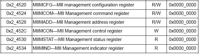
MIIMCFG 配置寄存器
MIIMCOM 命令寄存器
MIIMADD 地址寄存器
MIIMCON 控制寄存器
MIIMSTAT 状态寄存器
MIIMIND 指示寄存器
以MPC8560举例,这些寄存器在CCSR中的位置如下:
2.1 MIIMCFG:配置寄存器

ResetMgmt: 用于重置MDIO模块
MgmtClockSet:时钟设置,是CCB的 2的n次方之一
2.2 MIIMCOM 命令寄存器

ReadCycle: 0->1 触发MDIO读时序
2.3 MIIMADD 地址寄存器
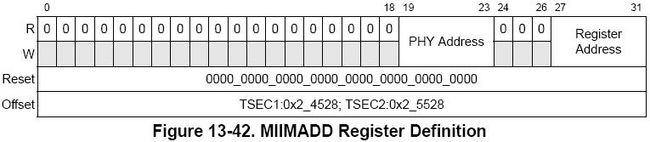
PHYaddr:PHY地址,共5bit,系统最多联31个PHY(地址0为保留)
REGaddr:寄存器地址,共5bit,一个PHY上最多32个寄存器地址(可以使用shadow value技术,访问更多的寄存器)
2.4 MIIMCON 控制寄存器

PHYcontrol:在写流程时,这里存放要写入寄存器的值
2.5 MIIMSTAT 状态寄存器

PHYstatus:读流程时,PHY reg的内容会放到此
2.6 MIIMIND 指示寄存器

NotVal:若置1,表示读流程结束,可以去读MIIMSTAT
Scan: 若置1,表示扫描流程进行中
Busy: 只有置0时,才能进行新的读写流程
3. linux中MDIO的实现
读写PHY寄存器时通过2个函数
phy_read()和phy_write(),
最终调用
int gfar_local_mdio_read(struct gfar_mii *regs, int mii_id, int regnum)
int gfar_local_mdio_write(struct gfar_mii *regs, int mii_id, int regnum, u16 value)
参数regs就是MDIO相关寄存器:
参数mii_id,就是PHY的id
参数regnum,就是寄存器地址
上代码,简单不解释
The MDIO interface is a simple, two-wire, serial interface to connect a management entity and a managed PHY for the purposes of controlling the PHY and gathering status from the PHY.
The two lines include the MDC line [Management Data Clock], and the MDIO line [Management Data Input/Output]. The clock is point-to-point, while the data line is a bi-directional multi-drop interface.
The data line is Tri-state able and can drive 32 devices.
MDIO接口,MAC与PHY间的管理接口(MII是数据接口),有2根线:时钟线MDC,数据线MDIO(双向)
MDIO工作流程:
* Preamle(PRE) 在没有传输数据的空闲状态时,数据线MDIO处于高阻态(一直为1)。
* Start of Frame(ST) MAC驱动MDIO线,出现一个2bit的开始标识码(01)。
* Operation Code(OP) MAC驱动MDIO线,出现一个2bit数据来标识是读操作(10)还是写操作(01)。
* PHY Address(PHYAD) MAC驱动MDIO线,出现一个5bit数据标识PHY的地址。
* Reg Address(REGAD) MAC驱动MDIO线,出现一个5bitPHY寄存器地址。
* Turnaround(TA) 写操作的话,MAC驱动MDIO线,出现10
读操作的话,MDIO pin of MAC must be put in high-impedance state
在第二个周期,PHY驱动MDIO线,出现0
* Data MDIO串行读出/写入16bit的寄存器数据。
* MDIO恢复成空闲状态,同时MDIO进入高阻状态。
下面是PHY芯片 BCM5461 的一个例子:
2. PowerPC对MDIO的支持
PowerPC操作MDIO时,涉及以下寄存器:
MIIMCFG 配置寄存器
MIIMCOM 命令寄存器
MIIMADD 地址寄存器
MIIMCON 控制寄存器
MIIMSTAT 状态寄存器
MIIMIND 指示寄存器
以MPC8560举例,这些寄存器在CCSR中的位置如下:
2.1 MIIMCFG:配置寄存器
ResetMgmt: 用于重置MDIO模块
MgmtClockSet:时钟设置,是CCB的 2的n次方之一
2.2 MIIMCOM 命令寄存器
ReadCycle: 0->1 触发MDIO读时序
2.3 MIIMADD 地址寄存器
PHYaddr:PHY地址,共5bit,系统最多联31个PHY(地址0为保留)
REGaddr:寄存器地址,共5bit,一个PHY上最多32个寄存器地址(可以使用shadow value技术,访问更多的寄存器)
2.4 MIIMCON 控制寄存器
PHYcontrol:在写流程时,这里存放要写入寄存器的值
2.5 MIIMSTAT 状态寄存器
PHYstatus:读流程时,PHY reg的内容会放到此
2.6 MIIMIND 指示寄存器
NotVal:若置1,表示读流程结束,可以去读MIIMSTAT
Scan: 若置1,表示扫描流程进行中
Busy: 只有置0时,才能进行新的读写流程
3. linux中MDIO的实现
读写PHY寄存器时通过2个函数
phy_read()和phy_write(),
最终调用
int gfar_local_mdio_read(struct gfar_mii *regs, int mii_id, int regnum)
int gfar_local_mdio_write(struct gfar_mii *regs, int mii_id, int regnum, u16 value)
参数regs就是MDIO相关寄存器:
- struct gfar_mii {
- u32 miimcfg; /* 0x.520 - MII Management Config Register */
- u32 miimcom; /* 0x.524 - MII Management Command Register */
- u32 miimadd; /* 0x.528 - MII Management Address Register */
- u32 miimcon; /* 0x.52c - MII Management Control Register */
- u32 miimstat; /* 0x.530 - MII Management Status Register */
- u32 miimind; /* 0x.534 - MII Management Indicator Register */
- };
参数regnum,就是寄存器地址
上代码,简单不解释
- int gfar_local_mdio_read(struct gfar_mii *regs, int mii_id, int regnum)
- {
- u16 value;
- /* Set the PHY address and the register address we want to read */
- gfar_write(®s->miimadd, (mii_id << 8) | regnum);
- /* Clear miimcom, and then initiate a read */
- gfar_write(®s->miimcom, 0);
- gfar_write(®s->miimcom, MII_READ_COMMAND);
- /* Wait for the transaction to finish */
- while (gfar_read(®s->miimind) & (MIIMIND_NOTVALID | MIIMIND_BUSY))
- cpu_relax();
- /* Grab the value of the register from miimstat */
- value = gfar_read(®s->miimstat);
- return value;
- }
- int gfar_local_mdio_write(struct gfar_mii *regs, int mii_id,
- int regnum, u16 value)
- {
- /* Set the PHY address and the register address we want to write */
- gfar_write(®s->miimadd, (mii_id << 8) | regnum);
- /* Write out the value we want */
- gfar_write(®s->miimcon, value);
- /* Wait for the transaction to finish */
- while (gfar_read(®s->miimind) & MIIMIND_BUSY)
- cpu_relax();
- return 0;
- }
转自:点击打开链接