stm32专题八:端口复用及重映射
stm32有很多的外设,这些外设的引脚都是与GPIO引脚复用的。也就是说,一个GPIO,既可以当作普通的IO口(此时按照通用配置),也可以配置为外设引脚(此时配置为复用输出/输入),如串口USART,IIC,之前提到的MCO系统时钟监测引脚等,接下来专门介绍端口复用和重映射。
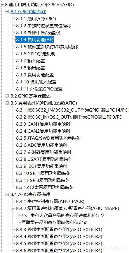
在stm32中文参考手册的第8章,有专门提到端口复用的章节如下
以下是关于复用功能的描述:
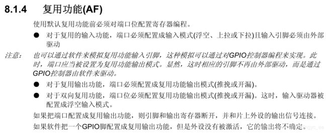
根据描述我们知道,在使用复用功能前,我们需要先配置对应的GPIO。具体配置的结构框图,也在“复用功能配置”中有说明。注意,在复用开漏模式下,读输入数据寄存器IDR可以得到IO口的状态,很明显,这在软件模拟IIC时,获得应答信号ACK非常有用。那么外设的GPIO具体应该怎么配置复用功能呢?在参考手册P110 8.1.11节有详细说明,所有外设的复用都能在这里查到。
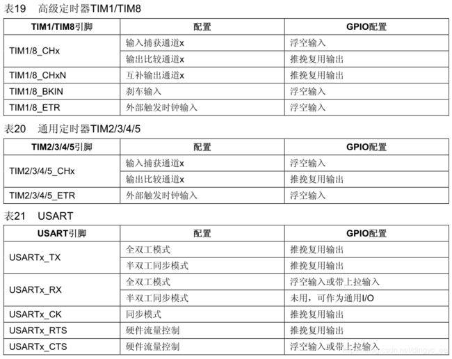
比如,当我们需要使用USART1时,按照上述复用功能的描述,首先需要开启GPIO的时钟,然后要开启USART1的时钟,然后按照上表来对相应的GPIO引脚进行配置。USART1_TX的默认引脚为PA9,则PA9要配置为推挽复用输出,RX引脚为PA10,按上表应配置为浮空输入,代码如下:
// 使能GPIOA的时钟
RCC_APB2PeriphClockCmd(RCC_APB2Periph_GPIOA,ENABLE);
// 使能USART1串口1的时钟
RCC_APB2PeriphClockCmd(RCC_APB2Periph_USART1, ENABLE);

// 将USART Tx的GPIO配置为推挽复用模式PA9
GPIO_InitStructure.GPIO_Pin = GPIO_Pin_9;
GPIO_InitStructure.GPIO_Mode = GPIO_Mode_AF_PP;
GPIO_InitStructure.GPIO_Speed = GPIO_Speed_50MHz;
GPIO_Init(GPIOA, &GPIO_InitStructure);

// 将USART Rx的GPIO配置为浮空输入模式PA10
GPIO_InitStructure.GPIO_Pin = GPIO_Pin_10;
GPIO_InitStructure.GPIO_Mode = GPIO_Mode_IN_FLOATING;
GPIO_Init(GPIOA, &GPIO_InitStructure);
所以,我们在使用复用功能的是时候,最少要使能 2 个时钟:
- GPIO 时钟使能
- 复用的外设时钟使能
- 同时要初始化 GPIO 以及复用外设功能
以上时端口复用的内容。
重映射
为了使不同器件封装的外设 IO 功能数量达到最优,可以把一些复用功能重新映射到其他一些引脚上。STM32 中有很多内置外设的输入输出引脚都具有重映射(remap)的功能。我们知道每个内置外设都有若干个输入输出引脚,一般这些引脚的输出端口都是固定不变的,为了让设计工程师可以更好地安排引脚的走向和功能,在 STM32 中引入了外设引脚重映射的概念,即一个外设的引脚除了具有默认的端口外,还可以通过设置重映射寄存器的方式,把这个外设的引脚映射到其它的端口。
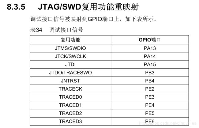
关于重映射的描述:
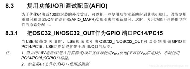
OSC32_IN和OSC32_OUT实际上就是连接外部低速晶振LSE(优先为LSE),也可以重映射为通用的GPIO口(PC14 PC15)。同理,OSC_IN和OSC_OUT连接HSE,可以重映射到PD0 PD1。
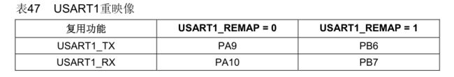
如串口USART1,下图所示。可以看到,REMAP=0(未开启重映射)即默认复用引脚为PA9 PA10,而当开启了重映射之后,TX和RX被重映射到PB6和PB7。重映射还有部分重映射(改变其中一些引脚分配)和完全重映射(改变所有引脚分配)。
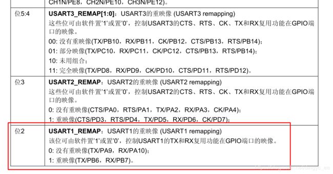
重映射实际上操作的是AFIO_MAPR寄存器,具体如下:

可以看到,其中包含了JTAG-SWD,ADC,TIM,USART,IIC,SPI等外设的重映射。操作起来也很简单,只需要对相应的位置1,就完成了重映射,比如USART1
因此,重映射的过程分为:
- 使能GPIO端口时钟;
- 使能外设的时钟;
- 使能AFIO的时钟(AFIO也是一个外设);
- 开启重映射,调用库函数GPIO_PinRemapConfig(uint32_t GPIO_Remap, FunctionalState NewState);
GOIO重映射的函数GPIO_PinRemapConfig包含在stm32f10x_gpio.h中,我们可以很方便的实现重映射,其源码如下。可以看到,其实就是往MAPR中相应的位写1。
/**
  * @brief  Enables or disables the Event Output.
  * @param  NewState: new state of the Event output.
  *   This parameter can be: ENABLE or DISABLE.
  * @retval None
  */
void GPIO_EventOutputCmd(FunctionalState NewState)
{
  /* Check the parameters */
  assert_param(IS_FUNCTIONAL_STATE(NewState));

  *(__IO uint32_t *) EVCR_EVOE_BB = (uint32_t)NewState;
}

/**
  * @brief  Changes the mapping of the specified pin.
  * @param  GPIO_Remap: selects the pin to remap.
  *   This parameter can be one of the following values:
  *     @arg GPIO_Remap_SPI1             : SPI1 Alternate Function mapping
  *     @arg GPIO_Remap_I2C1             : I2C1 Alternate Function mapping
  *     @arg GPIO_Remap_USART1           : USART1 Alternate Function mapping
  *     @arg GPIO_Remap_USART2           : USART2 Alternate Function mapping
  *     @arg GPIO_PartialRemap_USART3    : USART3 Partial Alternate Function mapping
  *     @arg GPIO_FullRemap_USART3       : USART3 Full Alternate Function mapping
  *     @arg GPIO_PartialRemap_TIM1      : TIM1 Partial Alternate Function mapping
  *     @arg GPIO_FullRemap_TIM1         : TIM1 Full Alternate Function mapping
  *     @arg GPIO_PartialRemap1_TIM2     : TIM2 Partial1 Alternate Function mapping
  *     @arg GPIO_PartialRemap2_TIM2     : TIM2 Partial2 Alternate Function mapping
  *     @arg GPIO_FullRemap_TIM2         : TIM2 Full Alternate Function mapping
  *     @arg GPIO_PartialRemap_TIM3      : TIM3 Partial Alternate Function mapping
  *     @arg GPIO_FullRemap_TIM3         : TIM3 Full Alternate Function mapping
  *     @arg GPIO_Remap_TIM4             : TIM4 Alternate Function mapping
  *     @arg GPIO_Remap1_CAN1            : CAN1 Alternate Function mapping
  *     @arg GPIO_Remap2_CAN1            : CAN1 Alternate Function mapping
  *     @arg GPIO_Remap_PD01             : PD01 Alternate Function mapping
  *     @arg GPIO_Remap_TIM5CH4_LSI      : LSI connected to TIM5 Channel4 input capture for calibration
  *     @arg GPIO_Remap_ADC1_ETRGINJ     : ADC1 External Trigger Injected Conversion remapping
  *     @arg GPIO_Remap_ADC1_ETRGREG     : ADC1 External Trigger Regular Conversion remapping
  *     @arg GPIO_Remap_ADC2_ETRGINJ     : ADC2 External Trigger Injected Conversion remapping
  *     @arg GPIO_Remap_ADC2_ETRGREG     : ADC2 External Trigger Regular Conversion remapping
  *     @arg GPIO_Remap_ETH              : Ethernet remapping (only for Connectivity line devices)
  *     @arg GPIO_Remap_CAN2             : CAN2 remapping (only for Connectivity line devices)
  *     @arg GPIO_Remap_SWJ_NoJTRST      : Full SWJ Enabled (JTAG-DP + SW-DP) but without JTRST
  *     @arg GPIO_Remap_SWJ_JTAGDisable  : JTAG-DP Disabled and SW-DP Enabled
  *     @arg GPIO_Remap_SWJ_Disable      : Full SWJ Disabled (JTAG-DP + SW-DP)
  *     @arg GPIO_Remap_SPI3             : SPI3/I2S3 Alternate Function mapping (only for Connectivity line devices)
  *                                        When the SPI3/I2S3 is remapped using this function, the SWJ is configured
  *                                        to Full SWJ Enabled (JTAG-DP + SW-DP) but without JTRST.
  *     @arg GPIO_Remap_TIM2ITR1_PTP_SOF : Ethernet PTP output or USB OTG SOF (Start of Frame) connected
  *                                        to TIM2 Internal Trigger 1 for calibration (only for Connectivity line devices)
  *                                        If the GPIO_Remap_TIM2ITR1_PTP_SOF is enabled the TIM2 ITR1 is connected to
  *                                        Ethernet PTP output. When Reset TIM2 ITR1 is connected to USB OTG SOF output.
  *     @arg GPIO_Remap_PTP_PPS          : Ethernet MAC PPS_PTS output on PB05 (only for Connectivity line devices)
  *     @arg GPIO_Remap_TIM15            : TIM15 Alternate Function mapping (only for Value line devices)
  *     @arg GPIO_Remap_TIM16            : TIM16 Alternate Function mapping (only for Value line devices)
  *     @arg GPIO_Remap_TIM17            : TIM17 Alternate Function mapping (only for Value line devices)
  *     @arg GPIO_Remap_CEC              : CEC Alternate Function mapping (only for Value line devices)
  *     @arg GPIO_Remap_TIM1_DMA         : TIM1 DMA requests mapping (only for Value line devices)
  *     @arg GPIO_Remap_TIM9             : TIM9 Alternate Function mapping (only for XL-density devices)
  *     @arg GPIO_Remap_TIM10            : TIM10 Alternate Function mapping (only for XL-density devices)
  *     @arg GPIO_Remap_TIM11            : TIM11 Alternate Function mapping (only for XL-density devices)
  *     @arg GPIO_Remap_TIM13            : TIM13 Alternate Function mapping (only for High density Value line and XL-density devices)
  *     @arg GPIO_Remap_TIM14            : TIM14 Alternate Function mapping (only for High density Value line and XL-density devices)
  *     @arg GPIO_Remap_FSMC_NADV        : FSMC_NADV Alternate Function mapping (only for High density Value line and XL-density devices)
  *     @arg GPIO_Remap_TIM67_DAC_DMA    : TIM6/TIM7 and DAC DMA requests remapping (only for High density Value line devices)
  *     @arg GPIO_Remap_TIM12            : TIM12 Alternate Function mapping (only for High density Value line devices)
  *     @arg GPIO_Remap_MISC             : Miscellaneous Remap (DMA2 Channel5 Position and DAC Trigger remapping,
  *                                        only for High density Value line devices)
  * @param  NewState: new state of the port pin remapping.
  *   This parameter can be: ENABLE or DISABLE.
  * @retval None
  */
void GPIO_PinRemapConfig(uint32_t GPIO_Remap, FunctionalState NewState)
{
  uint32_t tmp = 0x00, tmp1 = 0x00, tmpreg = 0x00, tmpmask = 0x00;

  /* Check the parameters */
  assert_param(IS_GPIO_REMAP(GPIO_Remap));
  assert_param(IS_FUNCTIONAL_STATE(NewState));

  if((GPIO_Remap & 0x80000000) == 0x80000000)
  {
    tmpreg = AFIO->MAPR2;
  }
  else
  {
    tmpreg = AFIO->MAPR;
  }

  tmpmask = (GPIO_Remap & DBGAFR_POSITION_MASK) >> 0x10;
  tmp = GPIO_Remap & LSB_MASK;

  if ((GPIO_Remap & (DBGAFR_LOCATION_MASK | DBGAFR_NUMBITS_MASK)) == (DBGAFR_LOCATION_MASK | DBGAFR_NUMBITS_MASK))
  {
    tmpreg &= DBGAFR_SWJCFG_MASK;
    AFIO->MAPR &= DBGAFR_SWJCFG_MASK;
  }
  else if ((GPIO_Remap & DBGAFR_NUMBITS_MASK) == DBGAFR_NUMBITS_MASK)
  {
    tmp1 = ((uint32_t)0x03) << tmpmask;
    tmpreg &= ~tmp1;
    tmpreg |= ~DBGAFR_SWJCFG_MASK;
  }
  else
  {
    tmpreg &= ~(tmp << ((GPIO_Remap >> 0x15)*0x10));
    tmpreg |= ~DBGAFR_SWJCFG_MASK;
  }

  if (NewState != DISABLE)
  {
    tmpreg |= (tmp << ((GPIO_Remap >> 0x15)*0x10));
  }

  if((GPIO_Remap & 0x80000000) == 0x80000000)
  {
    AFIO->MAPR2 = tmpreg;
  }
  else
  {
    AFIO->MAPR = tmpreg;
  }
}