Python计算机视觉编程第四章——照相机模型与增强现实
Python计算机视觉编程
- 照相机模型与增强现实
- (一)针孔照相机模型
- 1.1 照相机矩阵
- 1.2 三维点的投影
- 1.3 照相机矩阵的分解
- 1.4 计算照相机中心
- (二)照相机标定
- (三)以平面和标记物进行姿态估计
- (四)增强现实
- 4.1PyGame 和 PyOpenGL
- 4.2 从照相机矩阵到 OpenGL 格式
- 4.3 在图像中放置虚拟物体
照相机模型与增强现实
本章中,主要尝试对照相机进行建模,并有效地使用这些模型。为了处理三维图像和平面图像之间 的映射,我们需要在映射中加入部分照相机产生图像过程的投影特性。下面讲述如何确定照相机的参数,以及在具体应用中,如增强现实,如何使用图像间的投影变换。
(一)针孔照相机模型
在计算机视觉中,利用所拍摄的图像来计算出三维空间中被测物体的几何参数。图像是空间物体通过成像系统在像平面上的反映,即空间物体在像平面上的投影。
图像上每一个像素点的灰度反映了空间物体表面某点的反射光的强度,而该点在图像上的位置则与空间物体表面对应点的几何位置有关。这些位置的相互关系,由摄像机成像系统的几何投影模型所决定。
计算机视觉研究中,三维空间中的物体到像平面的投影关系即为成像模型,理想的投影成像模型是光学中的中心投影,也称为针孔模型。
针孔模型
- 假设物体表面的反射光都经过一个针孔而投影到像平面上,即满足光的直线传播条件。
- 针孔模型主要由光心(投影中心)、成像面和光轴组成。
- 小孔成像由于透光量太小,因此需要很长的曝光时间,并且很难得到清晰的图像。实际摄像系统通常都由透镜或者透镜组成。
- 两种模型具有相同的成像关系,即像点是物点和光心的连线与图像平面的交点。因此,可以用针孔模型作为照相机成像模型。
针孔照相机
针孔照相机模型(有时称为射影照相机模型)是计算机视觉中广泛使用的照相机模型。对于大多数应用来说,针孔照相机模型简单,并且具有足够的精确度。

空间点0是投影中心,它到平面π的距离是f。空间点M在平面π上的投影(或像)m是以点0为端点并经过点M的射线与平面π的交点。
平面π:摄像机的像平面
点0:摄像机中心(光心)
f:摄像机的焦距
以点0为端点且垂直于像平面的射线称为光轴或主轴,主轴与像平面的交点p称为摄像机的主点。
常用坐标系及其关系:
图像坐标系:
以图像左上角为原点建立以像素为单位的直接坐标系u-v。像素的横坐标u与纵坐标v分别是在其图像数组中所在的列数与所在行数。(在OpenCV中u对应x,v对应y)
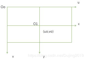
由于(u,v)只代表像素的列数与行数,而像素在图像中的位置并没有用物理单位表示出来,所以,我们还要建立以物理单位(如毫米)表示的图像坐标系x-y。将相机光轴与图像平面的交点(一般位于图像平面的中心处,也称为图像的主点(principal point)定义为该坐标系的原点O1,且x轴与u轴平行,y轴与v轴平行,假设(u0,v0)代表O1在u-v坐标系下的坐标,dx与dy分别表示每个像素在横轴x和纵轴y上的物理尺寸,则图像中的每个像素在u-v坐标系中的坐标和在x-y坐标系中的坐标之间都存在如下的关系:
![]()
![]()
其中,我们假设物理坐标系中的单位为毫米,那么dx的的单位为:毫米/像素。那么x/dx的单位就是像素了,即和u的单位一样都是像素。为了使用方便,可将上式用齐次坐标与矩阵形式表示为:

相机坐标系:
相机成像的几何关系可由图2表示。其中O点为摄像机光心(投影中心),Xc轴和Yc轴与成像平面坐标系的x轴和y轴平行,Zc轴为相机的光轴,和图像平面垂直。光轴与图像平面的交点为图像的主点O1,由点O与Xc,Yc,Zc轴组成的直角坐标系称为摄像机的坐标系。OO1为相机的焦距。
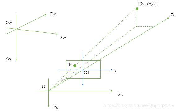
世界坐标系:也称真实或现实世界坐标系,或全局坐标系。世界坐标系是为了描述相机的位置而被引入的,如图2.2中坐标系OwXwYwZw即为世界坐标系。
世界坐标与相机坐标之间的转换关系:
平移向量t和旋转矩阵R可以用来表示相机坐标系与世界坐标系的关系。所以,假设空间点P在世界坐标系下的齐次坐标是(Xw,Yw,Zw,1)T,(这里T是上标转置),在相机坐标下的齐次坐标是(Xc,Yc,Zc,1)T,则存在如下的关系:

其中,
- R是3×3的正交单位矩阵(也称为旋转矩阵)
满足约束条件:


- T是三维的平移向量,矢量 ,是世界坐标系原点在照相机坐标系中的坐标。
- M1是4×4矩阵。

- 矩阵R实际上只含有三个独立变量 R x R_x Rx , R y R_y Ry, R z R_z Rz,再加上 t x t_x tx , t y t_y ty, t z t_z tz,总共六个参数决定了照相机光轴在世界坐标系的坐标,因此这六个参数称为照相机的外部参数。
图像坐标系与相机坐标系变换关系:
照相机坐标系中的一点P在图像物理坐标系中像点P坐标为:
![]()
![]()
齐次坐标表示为:
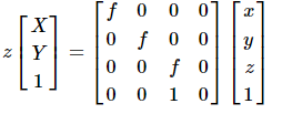
将上式图像物理坐标系进一步转化为图像坐标系:

其中, u 0 u_0 u0, v 0 v_0 v0是图像中心(光轴与图像平面的交点)坐标, d x d_x dx, d y d_y dy分别为一个像素在X于Y方向上的物理尺寸, s x s_x sx=1/ d x d_x dx, s y s_y sy=1/ d y d_y dy分别为X与Y方向上的采样频率,即单位长度的像素个数。
因此可得物点P与图像像素坐标系中像点 p f p_f pf的变换关系为:

其中, f x f_x fx=f s x s_x sx, f y f_y fy=f s y s_y sy分别定义为X和Y方向的等效焦距。 f x f_x fx, f y f_y fy, u o u_o uo, v o v_o vo这四个参数只与照相机内部结构有关,因此称为照相机的内部参数。
世界坐标系与图像坐标系变换关系:

转化为齐次坐标为:

这是针孔模型或者中心图像的数学表达式,在计算机内部参数确定的条件下 ,利用若干个已知的物点和相应的像点坐标,就可以求解出摄像机的内部和外部参数。
1.1 照相机矩阵
成像模型的代数表示
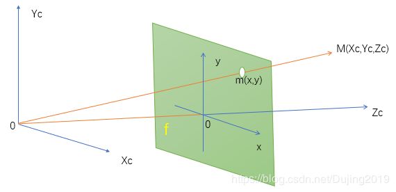
摄像机坐标系:O-XcXcZc
图像坐标系:O-XY
根据三角形相似原理,有
![]()
![]()
上式可表示为下面的矩阵:

其中


如果记P=diag(f,f,1)(I,0),则上式可表示为m=P X c X_c Xc,其中,矩阵P是一个3x4的矩阵,通常称它为照相机矩阵。
1.2 三维点的投影
1.3 照相机矩阵的分解
齐次坐标下,物体的物理坐标是 [x,y,z,1]′的形式,图像上对应点的坐标是 [u,v,1]′的形式,所以相机矩阵 P作为把物体映射成像的矩阵,应该是一个 3×4 的矩阵。
因此,照相机矩阵可以表示为如下形式:
![]()
| 代表的是增广矩阵
M 代表的是可逆的 3×3 的矩阵
C 是列向量,代表世界坐标系中相机的位置
要想求得 C, 只需要 P 的前三列组成的M, 求出来 −M−1 再乘以最后一列,就得到了 C矩阵的确可以把 3D的点投影到 2D 空间,但是,这种形式下表达的信息是很粗糙的,比如
- 没有提供相机的摆放姿态
- 没有相机内部的几何特征
为了挖掘这些信息,对矩阵进一步分解为一个内参矩阵和外参矩阵的乘积:
![]()
其中
- 矩阵R是rotation矩阵,因此是正交的;K是上三角矩阵. 对P的前三列进行RQ分解就可得到KR
- T=−RC, 是摄像机坐标系下世界坐标系原点的位置, tx,ty,tz分别代表世界坐标原点在相机的 左右,上下,前后 位置关系。在三维重建中,一组标定好了的图片序列,它们各自的相机矩阵中的T应该是相同的。
- 其中 K 就是内参,R,T 为外参。
如果给定照相机矩阵 P,我们需要恢复内参数 K 以及照相机的 位置t 和姿势R。矩阵分块操作称为因子分解。这里,我们将使用一种矩阵因子分 解的方法,称为 RQ 因子分解
将下面的方法添加到 Camera 类中:
    def factor(self):
        """    Factorize the camera matrix into K,R,t as P = K[R|t]. """

        # factor first 3*3 part
        K, R = linalg.rq(self.P[:, :3])

        # make diagonal of K positive
        T = diag(sign(diag(K)))
        if linalg.det(T) < 0:
            T[1, 1] *= -1

        self.K = dot(K, T)
        self.R = dot(T, R)  # T is its own inverse
        self.t = dot(linalg.inv(self.K), self.P[:, 3])

        return self.K, self.R, self.t
RQ 因子分解的结果并不是唯一的。在该因子分解中,分解的结果存在符号二义性。 由于我们需要限制旋转矩阵 R 为正定的(否则,旋转坐标轴即可),所以如果需要, 我们可以在求解到的结果中加入变换 T 来改变符号。
在示例照相机上运行下面的代码,观察照相机矩阵分解的效果:
import camera
from numpy import *
K = array([[1000,0,500],[0,1000,300],[0,0,1]])
tmp = camera.rotation_matrix([0,0,1])[:3,:3]
Rt = hstack((tmp,array([[50],[40],[30]])))
cam = camera.Camera(dot(K,Rt))
print K,Rt
print cam.factor()
1.4 计算照相机中心
给定照相机投影矩阵 P,我们可以计算出空间上照相机的所在位置。照相机的中心 C,是一个三维点,满足约束 PC=0。对于投影矩阵为 P=K[R|t] 的照相机,有:
注意,如预期一样,照相机的中心和内标定矩阵 K 无关。
下面的代码可以按照上面公式计算照相机的中心。将其添加到 Camera 类中,该方法会返回照相机的中心:
    def center(self):
        """计算并返回照相机的中心"""

        if self.c is not None:
            return self.c
        else:
            #通过因子分解计算c
            self.factor()
            self.c = -dot(self.R.T,self.t)
            return self.c
上面的一些方法构成了 Camera 类的基本函数操作。
(二)照相机标定
标定照相机是指计算出该照相机的内参数。在我们的例子中,是指计算矩阵 K。
需要准备一个平面矩形的标定物体(一个书本即可)、用于测 量的卷尺和直尺,以及一个平面。下面是具体操作步骤:
- 测量你选定矩形标定物体的边长dX 和 dY;
- 将照相机和标定物体放置在平面上,使得照相机的背面和标定物体平行,同时物体位于照相机图像视图的中心,你可能需要调整照相机或者物体来获得良好的对 齐效果;
- 测量标定物体到照相机的距离 dZ;
- 拍摄一副图像来检验该设置是否正确,即标定物体的边要和图像的行和列对齐;
- 使用像素数来测量标定物体图像的宽度和高度 dx和 dy
(三)以平面和标记物进行姿态估计
我们使用下面的代码来提取两幅图像的 SIFT 特征,然后使用 RANSAC 算法稳健地 估计单应性矩阵:
编写代码:
from PIL import Image
from numpy import *
from pylab import *
import os


def process_image(imagename, resultname, params="--edge-thresh 10 --peak-thresh 5"):
    """ Process an image and save the results in a file. """

    if imagename[-3:] != 'pgm':
        # create a pgm file
        im = Image.open(imagename).convert('L')
        im.save('tmp.pgm')
        imagename = 'tmp.pgm'

    cmmd = str("sift " + imagename + " --output=" + resultname +
               " " + params)
    os.system(cmmd)
    print 'processed', imagename, 'to', resultname


def read_features_from_file(filename):
    """ Read feature properties and return in matrix form. """

    f = loadtxt(filename)
    return f[:, :4], f[:, 4:]  # feature locations, descriptors


def write_features_to_file(filename, locs, desc):
    """ Save feature location and descriptor to file. """
    savetxt(filename, hstack((locs, desc)))


def plot_features(im, locs, circle=False):
    """ Show image with features. input: im (image as array),
        locs (row, col, scale, orientation of each feature). """

    def draw_circle(c, r):
        t = arange(0, 1.01, .01) * 2 * pi
        x = r * cos(t) + c[0]
        y = r * sin(t) + c[1]
        plot(x, y, 'b', linewidth=2)

    imshow(im)
    if circle:
        for p in locs:
            draw_circle(p[:2], p[2])
    else:
        plot(locs[:, 0], locs[:, 1], 'ob')
    axis('off')


def match(desc1, desc2):
    """ For each descriptor in the first image,
        select its match in the second image.
        input: desc1 (descriptors for the first image),
        desc2 (same for second image). """

    desc1 = array([d / linalg.norm(d) for d in desc1])
    desc2 = array([d / linalg.norm(d) for d in desc2])

    dist_ratio = 0.6
    desc1_size = desc1.shape

    matchscores = zeros((desc1_size[0]), 'int')
    desc2t = desc2.T  # precompute matrix transpose
    for i in range(desc1_size[0]):
        dotprods = dot(desc1[i, :], desc2t)  # vector of dot products
        dotprods = 0.9999 * dotprods
        # inverse cosine and sort, return index for features in second image
        indx = argsort(arccos(dotprods))

        # check if nearest neighbor has angle less than dist_ratio times 2nd
        if arccos(dotprods)[indx[0]] < dist_ratio * arccos(dotprods)[indx[1]]:
            matchscores[i] = int(indx[0])

    return matchscores


def appendimages(im1, im2):
    """ Return a new image that appends the two images side-by-side. """

    # select the image with the fewest rows and fill in enough empty rows
    rows1 = im1.shape[0]
    rows2 = im2.shape[0]

    if rows1 < rows2:
        im1 = concatenate((im1, zeros((rows2 - rows1, im1.shape[1]))), axis=0)
    elif rows1 > rows2:
        im2 = concatenate((im2, zeros((rows1 - rows2, im2.shape[1]))), axis=0)
    # if none of these cases they are equal, no filling needed.

    return concatenate((im1, im2), axis=1)


def plot_matches(im1, im2, locs1, locs2, matchscores, show_below=True):
    """ Show a figure with lines joining the accepted matches
        input: im1,im2 (images as arrays), locs1,locs2 (location of features),
        matchscores (as output from 'match'), show_below (if images should be shown below). """

    im3 = appendimages(im1, im2)
    if show_below:
        im3 = vstack((im3, im3))

    # show image
    imshow(im3)

    # draw lines for matches
    cols1 = im1.shape[1]
    for i, m in enumerate(matchscores):
        if m > 0:
            plot([locs1[i][0], locs2[m][0] + cols1], [locs1[i][1], locs2[m][1]], 'c')
    axis('off')


def match_twosided(desc1, desc2):
    """ Two-sided symmetric version of match(). """

    matches_12 = match(desc1, desc2)
    matches_21 = match(desc2, desc1)

    ndx_12 = matches_12.nonzero()[0]

    # remove matches that are not symmetric
    for n in ndx_12:
        if matches_21[int(matches_12[n])] != n:
            matches_12[n] = 0

    return matches_12
# -*- coding: utf-8 -*-
# -*- coding: utf-8 -*-
# -*- coding: cp936 -*-
from pylab import *
from PIL import Image
from numpy import *
# If you have PCV installed, these imports should work
from PCV.geometry import homography, camera
import sift

def my_calibration(sz):
    row, col = sz
    fx = 2555 * col / 2592
    fy = 2586 * row / 1936
    K = diag([fx, fy, 1])
    K[0, 2] = 0.5 * col
    K[1, 2] = 0.5 * row
    return K

def cube_points(c, wid):
    """ Creates a list of points for plotting
        a cube with plot. (the first 5 points are
        the bottom square, some sides repeated). """
    p = []
    # bottom
    p.append([c[0] - wid, c[1] - wid, c[2] - wid])
    p.append([c[0] - wid, c[1] + wid, c[2] - wid])
    p.append([c[0] + wid, c[1] + wid, c[2] - wid])
    p.append([c[0] + wid, c[1] - wid, c[2] - wid])
    p.append([c[0] - wid, c[1] - wid, c[2] - wid])  # same as first to close plot

    # top
    p.append([c[0] - wid, c[1] - wid, c[2] + wid])
    p.append([c[0] - wid, c[1] + wid, c[2] + wid])
    p.append([c[0] + wid, c[1] + wid, c[2] + wid])
    p.append([c[0] + wid, c[1] - wid, c[2] + wid])
    p.append([c[0] - wid, c[1] - wid, c[2] + wid])  # same as first to close plot

    # vertical sides
    p.append([c[0] - wid, c[1] - wid, c[2] + wid])
    p.append([c[0] - wid, c[1] + wid, c[2] + wid])
    p.append([c[0] - wid, c[1] + wid, c[2] - wid])
    p.append([c[0] + wid, c[1] + wid, c[2] - wid])
    p.append([c[0] + wid, c[1] + wid, c[2] + wid])
    p.append([c[0] + wid, c[1] - wid, c[2] + wid])
    p.append([c[0] + wid, c[1] - wid, c[2] - wid])

    return array(p).T


#  计算特征
sift.process_image('D:\\Python\\chapter4\\book_frontal.jpg', 'im0.sift')
l0, d0 = sift.read_features_from_file('im0.sift')

sift.process_image('D:\\Python\\chapter4\\book_perspective.jpg', 'im1.sift')
l1, d1 = sift.read_features_from_file('im1.sift')


#  匹配特征并计算单应性矩阵
matches = sift.match_twosided(d0, d1)
ndx = matches.nonzero()[0]
fp = homography.make_homog(l0[ndx, :2].T)
ndx2 = [int(matches[i]) for i in ndx]
tp = homography.make_homog(l1[ndx2, :2].T)

model = homography.RansacModel()
H, inliers = homography.H_from_ransac(fp, tp, model)

# 计算照相机标定矩阵
K = my_calibration((400, 300))

# 位于边长为0.2 z=0平面的三维点
box = cube_points([0, 0, 0.1], 0.1)

# 投影第一幅图像上底部的正方形
cam1 = camera.Camera(hstack((K, dot(K, array([[0], [0], [-1]])))))
# 底部正方形上的点
box_cam1 = cam1.project(homography.make_homog(box[:, :5]))


# 使用H将点变换到第二幅图像中
box_trans = homography.normalize(dot(H,box_cam1))

# 从cam1和H中计算第二个照相机矩阵
cam2 = camera.Camera(dot(H, cam1.P))
A = dot(linalg.inv(K), cam2.P[:, :3])
A = array([A[:, 0], A[:, 1], cross(A[:, 0], A[:, 1])]).T
cam2.P[:, :3] = dot(K, A)

# 使用第二个照相机矩阵投影
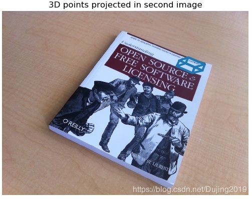
box_cam2 = cam2.project(homography.make_homog(box))


# plotting
im0 = array(Image.open('D:\\Python\\chapter4\\book_frontal.jpg'))
im1 = array(Image.open('D:\\Python\\chapter4\\book_perspective.jpg'))

figure()
imshow(im0)
plot(box_cam1[0, :], box_cam1[1, :], linewidth=3)
title('2D projection of bottom square')
axis('off')

figure()
imshow(im1)
plot(box_trans[0, :], box_trans[1, :], linewidth=3)
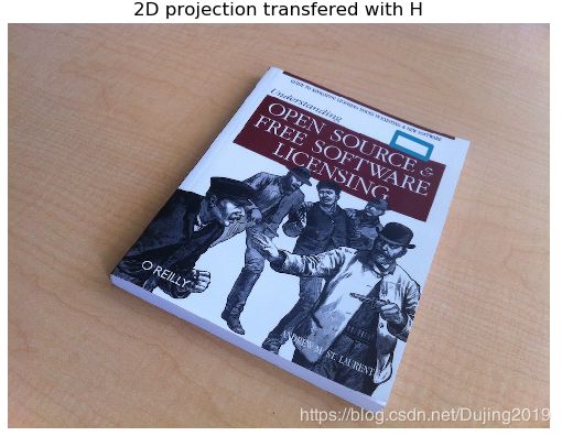
title('2D projection transfered with H')
axis('off')

figure()
imshow(im1)
plot(box_cam2[0, :], box_cam2[1, :], linewidth=3)
title('3D points projected in second image')
axis('off')

show()
(四)增强现实
增强现实(Augmented Reality,AR)是将物体和相应信息放置在图像数据上的一 系列操作的总称。最经典的例子是放置一个三维计算机图形学模型,使其看起来属于该场景;如果在视频中,该模型会随着照相机的运动很自然地移动。如上一节所示,给定一幅带有标记平面的图像,我们能够计算出照相机的位置和姿态,使用这些信息来放置计算机图形学模型,能够正确表示它们。其中,我们会用到两个工具包:PyGame 和 PyOpenGL。
4.1PyGame 和 PyOpenGL
安装PyGame
pip install pygame
安装PyOpenGL
pip install PyOpenGL-3.1.3b2-cp27-cp27m-win_amd64.whl
pip install PyOpenGL_accelerate-3.1.3b2-cp27-cp27m-win_amd64.whl
测试:
# -*- coding: utf-8 -*-
from OpenGL.GL import *
from OpenGL.GLU import *
from OpenGL.GLUT import *


def drawFunc():
    # 清除之前画面
    glClear(GL_COLOR_BUFFER_BIT)
    glRotatef(0.1, 5, 5, 0)  # (角度,x,y,z)
    glutSolidTeapot(0.5)  # 实心茶壶
    # 刷新显示
    glFlush()


# 使用glut初始化OpenGL
glutInit()
# 显示模式:GLUT_SINGLE无缓冲直接显示|GLUT_RGBA采用RGB(A非alpha)
glutInitDisplayMode(GLUT_SINGLE | GLUT_RGBA)
# 窗口位置及大小-生成
glutInitWindowPosition(0, 0)
glutInitWindowSize(400, 400)
glutCreateWindow(b"first")
# 调用函数绘制图像
glutDisplayFunc(drawFunc)
glutIdleFunc(drawFunc)
# 主循环
glutMainLoop()
4.2 从照相机矩阵到 OpenGL 格式
OpenGL 使用4×4 的矩阵来表示变换(包括三维变换和投影)。这和我们使用 的 3×4 照相机矩阵略有差别。但是,照相机与场景的变换分成了两个矩阵,GL_PROJECTION 矩阵和GL_MODELVIEW 矩阵GL_PROJECTION 矩阵处理图像成像的性质,等价于我们的内标定矩阵 K。GL_MODELVIEW 矩阵处理物体和照 相机之间的三维变换关系,对应于我们照相机矩阵中的R 和 t 部分。一个不同之处是,假设照相机为坐标系的中心,GL_MODELVIEW 矩阵实际上包含了将物体放置 在照相机前面的变换。
假设我们已经获得了标定好的照相机,即已知标定矩阵 K,下面的函数可以将照相机参数转换为 OpenGL 中的投影矩阵:
def set_projection_from_camera(K):
    glMatrixMode(GL_PROJECTION)
    glLoadIdentity()
    fx = K[0, 0]
    fy = K[1, 1]
    fovy = 2 * math.atan(0.5 * height / fy) * 180 / math.pi
    aspect = (width * fy) / (height * fx)
    near = 0.1
    far = 100.0
    gluPerspective(fovy, aspect, near, far)
    glViewport(0, 0, width, height)
第 一个 函 数 glMatrixMode() 将工作矩阵设置为 GL_PROJECTION,接下来的命令会修改这个矩 阵 1。 然后,glLoadIdentity() 函数将该矩阵设置为单位矩阵,这是重置矩阵的一般 操作。然后,我们根据图像的高度、照相机的焦距以及纵横比,计算出视图中的垂 直场。OpenGL 的投影同样具有近距离和远距离的裁剪平面来限制场景拍摄的深度 范围。我们设置近深度为一个小的数值,使得照相机能够包含最近的物体,而远深 度设置为一个大的数值。我们使用 GLU 的实用函数 gluPerspective() 来设置投影矩 阵,将整个图像定义为视图部分(也就是显示的部分)。和下面的模拟视图函数相 似,你可以使用 glLoadMatrixf() 函数的一个选项来定义一个完全的投影矩阵。当简单版本的标定矩阵不够好时,可以使用完全投影矩阵。
模拟视图矩阵能够表示相对的旋转和平移,该变换将该物体放置在照相机前(效果是照相机在原点上)。模拟视图矩阵是个典型的 4×4 矩阵,如下所示:

其中,R 是旋转矩阵,列向量表示 3 个坐标轴的方向,t 是平移向量。当创建模拟视图矩阵时,旋转矩阵需要包括所有的旋转(物体和坐标系的旋转),可以将单个旋转分量相乘来获得旋转矩阵。
4.3 在图像中放置虚拟物体
编写代码:
# -*- coding: utf-8 -*-
import math
import pickle
import sys
from pylab import *
from OpenGL.GL import *
from OpenGL.GLU import *
from OpenGL.GLUT import *
import pygame, pygame.image
from pygame.locals import *
from PCV.geometry import homography, camera
from PCV.localdescriptors import sift


def cube_points(c, wid):  # 绘制立方体的一各点列表
    """ Creates a list of points for plotting
        a cube with plot. (the first 5 points are
        the bottom square, some sides repeated). """
    p = []
    # 底部
    p.append([c[0] - wid, c[1] - wid, c[2] - wid])
    p.append([c[0] - wid, c[1] + wid, c[2] - wid])
    p.append([c[0] + wid, c[1] + wid, c[2] - wid])
    p.append([c[0] + wid, c[1] - wid, c[2] - wid])
    p.append([c[0] - wid, c[1] - wid, c[2] - wid])  # 和第一个相同

    # 顶部
    p.append([c[0] - wid, c[1] - wid, c[2] + wid])
    p.append([c[0] - wid, c[1] + wid, c[2] + wid])
    p.append([c[0] + wid, c[1] + wid, c[2] + wid])
    p.append([c[0] + wid, c[1] - wid, c[2] + wid])
    p.append([c[0] - wid, c[1] - wid, c[2] + wid])  # 和第一个相同

    # 竖直边
    p.append([c[0] - wid, c[1] - wid, c[2] + wid])
    p.append([c[0] - wid, c[1] + wid, c[2] + wid])
    p.append([c[0] - wid, c[1] + wid, c[2] - wid])
    p.append([c[0] + wid, c[1] + wid, c[2] - wid])
    p.append([c[0] + wid, c[1] + wid, c[2] + wid])
    p.append([c[0] + wid, c[1] - wid, c[2] + wid])
    p.append([c[0] + wid, c[1] - wid, c[2] - wid])

    return array(p).T


def my_calibration(sz):
    row, col = sz
    fx = 2555 * col / 2592
    fy = 2586 * row / 1936
    K = diag([fx, fy, 1])
    K[0, 2] = 0.5 * col
    K[1, 2] = 0.5 * row
    return K


def set_projection_from_camera(K):  # 获取视图
    glMatrixMode(GL_PROJECTION)
    glLoadIdentity()
    fx = K[0, 0]
    fy = K[1, 1]
    fovy = 2 * math.atan(0.5 * height / fy) * 180 / math.pi
    aspect = (width * fy) / (height * fx)
    # 定义近和远的剪裁平面
    near = 0.1
    far = 100.0
    # 设定透视
    gluPerspective(fovy, aspect, near, far)
    glViewport(0, 0, width, height)


def set_modelview_from_camera(Rt):  # 获取矩阵
    glMatrixMode(GL_MODELVIEW)
    glLoadIdentity()
    # 围绕x轴将茶壶旋转90度,使z轴向上
    Rx = np.array([[1, 0, 0], [0, 0, -1], [0, 1, 0]])
    # 获得旋转的最佳逼近
    R = Rt[:, :3]
    U, S, V = np.linalg.svd(R)
    R = np.dot(U, V)
    R[0, :] = -R[0, :]  # 改变x轴的符号
    # 获得平移量
    t = Rt[:, 3]
    # 获得4*4的的模拟视图矩阵
    M = np.eye(4)
    M[:3, :3] = np.dot(R, Rx)
    M[:3, 3] = t
    # 转置并压平以获取列序数值
    M = M.T
    m = M.flatten()
    # 将模拟视图矩阵替换成新的矩阵
    glLoadMatrixf(m)


def draw_background(imname):
    # 载入背景图像
    bg_image = pygame.image.load(imname).convert()
    bg_data = pygame.image.tostring(bg_image, "RGBX", 1)  # 将图像转为字符串描述
    glMatrixMode(GL_MODELVIEW)  # 将当前矩阵指定为投影矩阵
    glLoadIdentity()  # 把矩阵设为单位矩阵

    glClear(GL_COLOR_BUFFER_BIT | GL_DEPTH_BUFFER_BIT)  # 清楚颜色、深度缓冲
    glEnable(GL_TEXTURE_2D)  # 纹理映射
    glBindTexture(GL_TEXTURE_2D, glGenTextures(1))
    glTexImage2D(GL_TEXTURE_2D, 0, GL_RGBA, width, height, 0, GL_RGBA, GL_UNSIGNED_BYTE, bg_data)
    glTexParameterf(GL_TEXTURE_2D, GL_TEXTURE_MAG_FILTER, GL_NEAREST)
    glTexParameterf(GL_TEXTURE_2D, GL_TEXTURE_MIN_FILTER, GL_NEAREST)
    # 绑定纹理
    glBegin(GL_QUADS)
    glTexCoord2f(0.0, 0.0);
    glVertex3f(-1.0, -1.0, -1.0)
    glTexCoord2f(1.0, 0.0);
    glVertex3f(1.0, -1.0, -1.0)
    glTexCoord2f(1.0, 1.0);
    glVertex3f(1.0, 1.0, -1.0)
    glTexCoord2f(0.0, 1.0);
    glVertex3f(-1.0, 1.0, -1.0)
    glEnd()
    glDeleteTextures(1)  # 清除纹理


def draw_teapot(size):  # 红色茶壶
    glEnable(GL_LIGHTING)
    glEnable(GL_LIGHT0)
    glEnable(GL_DEPTH_TEST)
    glClear(GL_DEPTH_BUFFER_BIT)
    # 绘制红色茶壶
    glMaterialfv(GL_FRONT, GL_AMBIENT, [0, 0, 0, 0])
    glMaterialfv(GL_FRONT, GL_DIFFUSE, [0.5, 0.0, 0.0, 0.0])
    glMaterialfv(GL_FRONT, GL_SPECULAR, [0.7, 0.6, 0.6, 0.0])
    glMaterialf(GL_FRONT, GL_SHININESS, 0.25 * 128.0)
    glutSolidTeapot(size)


def drawFunc(size):  # 白色茶壶
    glRotatef(0.5, 5, 5, 0)  # (角度,x,y,z)
    glutWireTeapot(size)
    # 刷新显示
    glFlush()


width, height = 1000, 747


def setup():  # 设置窗口和pygame环境
    pygame.init()
    pygame.display.set_mode((width, height), OPENGL | DOUBLEBUF)
    pygame.display.set_caption("OpenGL AR demo")


# 计算特征
sift.process_image('D:\\Python\\chapter4\\book_frontal.jpg', 'im0.sift')
l0, d0 = sift.read_features_from_file('im0.sift')

sift.process_image('D:\\Python\\chapter4\\book_perspective.jpg', 'im1.sift')
l1, d1 = sift.read_features_from_file('im1.sift')

# 匹配特征,计算单应性矩阵
matches = sift.match_twosided(d0, d1)
ndx = matches.nonzero()[0]
fp = homography.make_homog(l0[ndx, :2].T)
ndx2 = [int(matches[i]) for i in ndx]
tp = homography.make_homog(l1[ndx2, :2].T)

model = homography.RansacModel()
H, inliers = homography.H_from_ransac(fp, tp, model)

# 计算照相机标定矩阵
K = my_calibration((747, 1000))
# 位于边长为0.2,z=0平面上的三维点
box = cube_points([0, 0, 0.1], 0.1)

# 投影第一幅图下个上底部的正方形
cam1 = camera.Camera(hstack((K, dot(K, array([[0], [0], [-1]])))))
# 底部正方形上的点
box_cam1 = cam1.project(homography.make_homog(box[:, :5]))

# 使用H将点变换到第二幅图像中
box_trans = homography.normalize(dot(H, box_cam1))

# 从cam1和H中计算第二个照相机矩阵
cam2 = camera.Camera(dot(H, cam1.P))
A = dot(linalg.inv(K), cam2.P[:, :3])
A = array([A[:, 0], A[:, 1], cross(A[:, 0], A[:, 1])]).T
cam2.P[:, :3] = dot(K, A)
# 使用第二个照相机矩阵投影
box_cam2 = cam2.project(homography.make_homog(box))

Rt = dot(linalg.inv(K), cam2.P)
setup()
draw_background("D:\\Python\\chapter4\\book_perspective.bmp")
set_projection_from_camera(K)
set_modelview_from_camera(Rt)

#draw_teapot(0.05)  # 显示红色茶壶
drawFunc(0.05)  # 显示白色空心茶壶
pygame.display.flip()
while True:
    for event in pygame.event.get():
        if event.type == pygame.QUIT:
            sys.exit()
代码运行效果如下:


