HCIP 综合实验(一)
综合实验
- 一、交换部分
- 1.Trunk配置
- 2.聚合VLAN
- 3.配置MSTP协议
- 二、路由部分
- 1.配置IS-IS 协议
- 2.路由聚合
- 3.缺省路由
- 4.区域认证
- 5.OSPF
- 6.配置BGP路由协议
- 7.路由引入
交换部分运行 生成树协议 STP
OSPF和ISIS间用 BGP协议
把各个协议引入到BGP,从而使路由连通
R1\R2\R3\R4 跑BGP协议
先从交换做起,再IGP协议,再BGP协议,再考虑路由连通性
最终结果是 用LSW2 ping通 顶端的路由器, PC是ping不通的,没有跑下放路由,也没用跑任何路由协议,不具有连通性
 基本的IP地址配置
1、基本配置
R1:
sys
sysname R1
int loop 0
ip add 1.1.1.1 24
int g0/0/1
ip add 192.168.13.1 24
int g0/0/0
ip add 192.168.12.1 24
int g0/0/3
ip add 192.168.18.1 24
int g0/0/2
ip add 192.168.17.1 24
q

R2:
sys
sysname R2
int loop 0
ip add 2.2.2.2 24
int g0/0/2
ip add 192.168.24.2 24
int g0/0/0
ip add 192.168.12.2 24
int g0/0/3
ip add 192.168.27.2 24
int g0/0/1
ip add 192.168.28.2 24
q

R3:
sys
sysname R3
int loop 0
ip add 3.3.3.3 24
int g0/0/0
ip add 192.168.35.3 24
int g0/0/2
ip add 192.168.34.3 24
int g0/0/1
ip add 192.168.13.3 24
q

R4:
sys
sysname R4
int loop 0
ip add 4.4.4.4 32
int g0/0/1
ip add 192.168.45.4 24
int g0/0/0
ip add 192.168.34.4 24
int g0/0/2
ip add 192.168.24.4 24
q

R5:
sys
sysname R5
int loop 0
ip add 5.5.5.5 24
int loop 1
ip add 55.55.55.55 24
int g0/0/0
ip add 192.168.35.5 24
int g0/0/1
ip add 192.168.45.5 24
q

S2:
sys
sysname S2
int vlanif 71
ip add 192.168.17.7 24
int vlanif 72
ip add 192.168.27.7 24
int loop 0
ip add 7.7.7.7 24
q

S3:
sys
sysname S3
int vlanif 81
ip add 192.168.18.8 24
int vlanif 82
ip add 192.168.28.8 24
int loop 0
ip add 8.8.8.8 24
q
一、交换部分
1.Trunk配置
为了保证不同交换机上同一个VLAN的成员之间能够相互通信,需要配置交换机之间相连的端口为Trunk端口,并允许相应VLAN通过。交换机都已经创建了VLAN 2、VLAN 3、VLAN 4、VLAN 10、VLAN 20、VLAN 30。
SW1:
int g0/0/1
port link-type trunk
port trunk allow-pass vlan all
int g0/0/2
port link-type trunk
port trunk allow-pass vlan all
SW2:
int g0/0/1
port link-type trunk
port trunk allow-pass vlan all
int g0/0/3
port link-type trunk
port trunk allow-pass vlan all
SW3:
int g0/0/2
port link-type trunk
port trunk allow-pass vlan all
int g0/0/3
port link-type trunk
port trunk allow-pass vlan all
2.聚合VLAN
在SW1上将PC1添加到VLAN 2,PC2 添加到VLAN 3。配置VLAN 4的IP地址为70.1.30.2/24,为Super VLAN,并配置 Proxy ARP。既可以实现VLAN 2和VLAN 3之间的通信,又可以节约IP地址资源
SW1:
vlan batch 2 3 4 10 20 30
int e0/0/1
port link-type access
port default vlan 2
int e0/0/2
port link-type access
port default vlan 3
聚合VLAN是不能包含任何物理接口的
VLAN 4 做聚合,配置聚合VLAN
SW1:
int g0/0/1
undo port trunk allow-pass vlan 4
int g0/0/2
undo port trunk allow-pass vlan 4
vlan 4
aggregate-vlan
access-vlan 2 3
int vlanif 4
ip add 70.1.30.2 24
arp-proxy inter-sub-vlan-proxy enable
PC之间测试:ping 70.1.30.4
3.配置MSTP协议
为了防止网络中的二层环路,同时对不同VLAN间的流量进行负载分担,配置所有的交换机都工作在MSTP模式。
创建MSTP域 huawei,修订版本号都为1。
实例 1 包含VLAN 2 和 VLAN 3,并以SW2为根交换机,实例2 中作为次根,
实例 2 包含VLAN 10、VLAN 20和VLAN 30,并以SW3为根交换机,实例1 中作为次根
为了保证交换网络中加了其他不支持MSTP的交换机后,SW2仍为整个生成树的根交换机,使用命令配置SW2为CIST的总根
SW1:
stp mode mstp
stp region-configuration
region-name huawei
revision-level 1
instance 1 vlan 2 3
instance 2 vlan 10 20 30
active region-configuration
SW2:
stp mode mstp
stp region-configuration
region-name huawei
revision-level 1
instance 1 vlan 2 3
instance 2 vlan 10 20 30
active region-configuration
SW3:
stp mode mstp
stp region-configuration
region-name huawei
revision-level 1
instance 1 vlan 2 3
instance 2 vlan 10 20 30
active region-configuration
考虑根的问题,SW2成为整个域的根
实例1中成为主根,实例2中成为辅根
SW2:
stp instance 0 priority 0
stp instance 1 priority 0
stp instance 2 priority 4096
SW3:
stp instance 1 priority 4096
stp instance 2 priority 0
验证是否为交叉阻塞
SW1:
dis stp brief
查看是否配置为交叉阻塞,instance 1阻塞 g0/0/2 ,instance 2 阻塞 g0/0/1
不同的实例阻塞不同的端口,从而达到负载均衡
BPDU保护
哪些设备有边缘端口就哪些做
为加快收敛,将交换机SW1的连接PC的端口设置为边缘端口,并配置保护功能以防止这些端口因收到不合法的BPDU而影响生成树的计算
int e0/0/1
stp edged-port enable
int e0/0/2
stp edged-port enable
全局下:stp bpdu-protection
查看端口保护模式
dis stp brief
二、路由部分
1.配置IS-IS 协议
公司总部内R1、R2、SW2、SW3运行IS-IS协议,并且都属于同一个区域。
默认是发L1和L2的,下面会进行优化
R1:
isis
network-entity 10.0000.0000.0001.00
is-name R1
int loo 0
isis enable
int g0/0/0
isis enable
int g0/0/2
isis enable
int g0/0/3
isis enable
R2:
isis
network-entity 10.0000.0000.0002.00
is-name R2
int loo 0
isis enable
int g0/0/0
isis enable
int g0/0/1
isis enable
int g0/0/3
isis enable
SW2:
R1 和 SW2连接是192.168.17.0 网段,而且拓扑图已经设置为 VLANIF71:192.168.17.7 , 因此g0/0/2 就放到 vlan 71
int g0/0/2
port link-type access
port default vlan 71
int g0/0/4
port link-type access
port default vlan 72
isis
network-entity 10.0000.0000.0007.00
is-name SW2
int loo 0
isis enable
int vlanif 71
isis enable
int vlanif 72
isis enable
SW3:
int g0/0/1
port link-type access
port default vlan 82
int g0/0/4
port link-type access
port default vlan 81
isis
network-entity 10.0000.0000.0008.00
is-name SW3
int loo 0
isis enable
int vlanif 81
isis enable
int vlanif 82
isis enable
查看IS-IS邻居的建立

2.路由聚合
在SW2、SW3中将VLAN 10、VLAN 20、VLAN 30接口所涉及的用户引入 IS-IS协议。另外,为了减少路由条目,需要将连续网段的路由进行聚合
SW2:
int vlanif 10
ip add 70.1.10.1 24
int vlanif 20
ip add 70.1.20.1 24
int vlanif 30
ip add 70.1.30.1 24
isis
import-route direct
summary 70.1.0.0 255.255.224.0
SW3:
int vlan 10
ip add 80.1.10.1 24
int vlan 20
ip add 80.1.20.1 24
int vlan 30
ip add 80.1.30.1 24
isis
import-route direct
summary 80.1.0.0 255.255.224.0
配置完成后,查看R1的路由表
display ip routing-table
为了减少LSP数量以优化网络,修改所有IS-IS接口的网络类型为P2P,这样就不会选举DIS。 默认DIS优先级是64,最大127
环回口默认就不会选举DIS的,虚拟的接口
display isis interface
R1:
int g0/0/0
isis circuit-type p2p
int g0/0/2
isis circuit-type p2p
int g0/0/3
isis circuit-type p2p
R2:
int g0/0/0
isis circuit-type p2p
int g0/0/1
isis circuit-type p2p
int g0/0/3
isis circuit-type p2p
SW2:
int vlan 71
isis circuit-type p2p
int vlan 72
isis circuit-type p2p
SW3:
int vlan 81
isis circuit-type p2p
int vlan 82
isis circuit-type p2p
配置完成后,查看一下
< R1 >display isis interface

3.缺省路由
SW2、SW3不允许BGP协议,为了使其能访问外网,需要在路由R1和R2上配置IS-IS下发缺省路由,默认下发的是Level-2
R1:
isis
default-route-advertise 默认是always
R2:
isis
default-route-advertise
SW2:查看一下路由表 dis ip routing-table
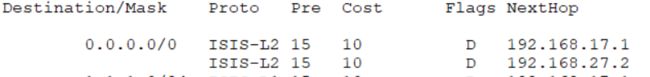
可以看到收到了缺省路由,并采用了负载分担
4.区域认证
R1
isis
area-authentication-mode md5 huawei
R2
isis
area-authentication-mode md5 huawei
SW2
isis
area-authentication-mode md5 huawei
SW3
isis
area-authentication-mode md5 huawei
5.OSPF
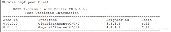
根据公司分部网络的设计,配置分部的所有路由器R3、R4、R5运行OSPF协议,router-id采用手工指定的方式
R3:
ospf router-id 3.3.3.3
area 0
network 3.3.3.3 0.0.0.0
net 192.168.35.3 0.0.0.0
net 192.168.34.3 0.0.0.0
R4
ospf router-id 4.4.4.4
area 0
net 4.4.4.4 0.0.0.0
net 192.168.34.4 0.0.0.0
net 192.168.45.4 0.0.0.0
R5:
ospf router-id 5.5.5.5
area 0
net 5.5.5.5 0.0.0.0
net 55.55.55.55 0.0.0.0
net 192.168.35.5 0.0.0.0
net 192.168.45.5 0.0.0.0
查看邻居状态 dis ospf peerbrief
6.配置BGP路由协议
在R1、R2、R3、R4、R5上配置BGP协议
R1与R3,R2与R4采用直连物理接口建立EBGP邻居关系。
R1与R2使用 loopback 0 建立IBGP邻居关系,R3、R4与R5使用loopback 0建立IBGP邻居关系。
R1: 环回口已经在ISIS宣告了,这里不需要宣告
bgp 100
router-id 1.1.1.1
peer 192.168.13.3 as-number 200
peer 2.2.2.2 as-number 100
peer 2.2.2.2 connect-interface loopback 0
peer 2.2.2.2 next-hop-local
R2:
bgp 100
router-id 2.2.2.2
peer 192.168.24.2 as-number 200
peer 1.1.1.1 as-number 100
peer 1.1.1.1 connect-interface loopback 0
peer 1.1.1.1 next-hop-local
R3:
bgp 200
router-id 3.3.3.3
peer 192.168.13.1 as-number 100
peer 4.4.4.4 as-number 200
peer 4.4.4.4 connect-interface loopback 0
peer 4.4.4.4 next-hop-local
peer 5.5.5.5 as-number 200
peer 5.5.5.5 connect-interface loopback0
peer 5.5.5.5 next-hop-local
R4:
bgp 200
router-id 4.4.4.4
peer 192.168.24.2 as-number 100
peer 3.3.3.3 as-number 200
peer 3.3.3.3 connect-interface loopback 0
peer 3.3.3.3 next-hop-local
peer 5.5.5.5 as-number 200
peer 5.5.5.5 connect-interface loopback 0
peer 5.5.5.5 next-hop-local
R5:
bgp 200
router-id 5.5.5.5
peer 3.3.3.3 as-n 200
peer 3.3.3.3 con loo0
peer 4.4.4.4 as-n 200
peer 4.4.4.4 con loo0
配置完成后,R查看BGP邻居
< R3 >dis bgp peer

7.路由引入
融合这些路由
为了将公司总部的路由信息通知给公司分布,在R1和R2上将IS-IS的路由信息引入到BGP协议。
R1:
bgp 100
import-route isis 1
R2:
bgp 100
import-route isis 1
为了让公司总部知道公司分部的路由,在R3和R4上 将OSPF路由引入BGP协议
R3:
bgp 200
import-route ospf 1
R4:
bgp 200
import-route ospf 1
现在网络除了两台PC是内部网络外,其他的设备可以相互通信
< SW2 >ping -a 7.7.7.7 5.5.5.5
ISIS 放到BGP里后,如何把BGP 放到ISIS里呢? 下放默认路由 (引入BGP不现实)
OSPF 放到BGP