使用openMV3与stm32进行通讯
使用openMV3与stm32进行通讯
想用openMV与stm32通讯,在网上找了一大圈,最后决定使用串口
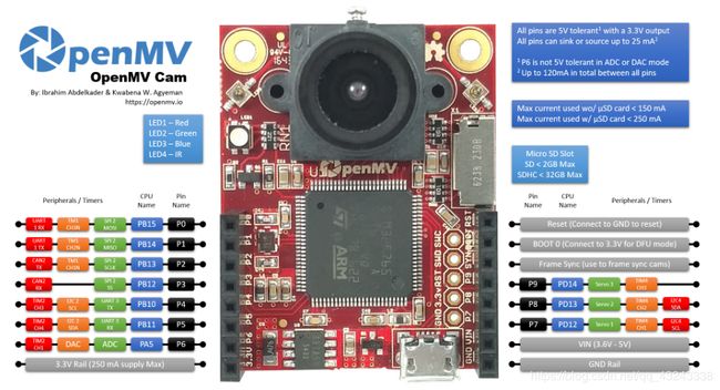
可以找到openMV的引脚资源图如下:

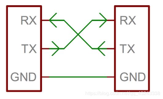
这里使用P4(USART3_TX)与P5(USART3_RX)脚与stm32的USART1交叉联接。

openMV的代码如下,功能是进行色块识别并把中心点传给stm32,需要注意的是对数据的打包格式,用到了ustruct.pack这个函数:
import sensor, image, time, math
from pyb import UART
import json
import ustruct


#white_threshold_01 = ((95, 100, -18, 3, -8, 4));  #白色阈值
red_threshold_01 = ((35, 100, 41, 77, 24, 59));
sensor.reset()
sensor.set_pixformat(sensor.RGB565)
sensor.set_framesize(sensor.QVGA)
sensor.skip_frames(time = 2000)
sensor.set_auto_gain(False) # must be turned off for color tracking
sensor.set_auto_whitebal(False) # must be turned off for color tracking
clock = time.clock()

uart = UART(3,115200)   #定义串口3变量
uart.init(115200, bits=8, parity=None, stop=1) # init with given parameters

def find_max(blobs):    #定义寻找色块面积最大的函数
    max_size=0
    for blob in blobs:
        if blob.pixels() > max_size:
            max_blob=blob
            max_size = blob.pixels()
    return max_blob

def sending_data(cx,cy):
    global uart;
    #frame=[0x2C,18,cx%0xff,int(cx/0xff),cy%0xff,int(cy/0xff),0x5B];
    #data = bytearray(frame)
    data = ustruct.pack(",              #格式为俩个字符俩个短整型(2字节)
                   0x2C,                       #帧头1
                   0x12,                       #帧头2
                   int(cx), # up sample by 4    #数据1
                   int(cy), # up sample by 4    #数据2
                   0x5B)
    uart.write(data);   #必须要传入一个字节数组

def recive_data():
    global uart
    if uart.any():
        tmp_data = uart.readline();
        print(tmp_data)


#mainloop
while(True):
    clock.tick() # Track elapsed milliseconds between snapshots().
    img = sensor.snapshot() # Take a picture and return the image.
    #  pixels_threshold=100, area_threshold=100
    blobs = img.find_blobs([red_threshold_01], area_threshold=150);
    cx=0;cy=0;
    if blobs:
        #如果找到了目标颜色
        max_b = find_max(blobs);
        # Draw a rect around the blob.
        img.draw_rectangle(max_b[0:4]) # rect
        #用矩形标记出目标颜色区域
        img.draw_cross(max_b[5], max_b[6]) # cx, cy
        img.draw_cross(160, 120) # 在中心点画标记
        #在目标颜色区域的中心画十字形标记
        cx=max_b[5];
        cy=max_b[6];
        img.draw_line((160,120,cx,cy), color=(127));
        #img.draw_string(160,120, "(%d, %d)"%(160,120), color=(127));
        img.draw_string(cx, cy, "(%d, %d)"%(cx,cy), color=(127));

    sending_data(cx,cy); #发送点位坐标
    recive_data();
    #time.sleep(1000)

#pack各字母对应类型
#x   pad byte        no value            1
#c   char            string of length 1  1
#b   signed char     integer             1
#B   unsigned char   integer             1
#?   _Bool           bool                1
#h   short           integer             2
#H   unsigned short  integer             2
#i   int             integer             4
#I   unsigned int    integer or long     4
#l   long            integer             4
#L   unsigned long   long                4
#q   long long       long                8
#Q   unsilong long   long                8
#f   float           float               4
#d   double          float               8
#s   char[]          string              1
#p   char[]          string              1
#P   void *          long
stm32端接收到一帧数据并解包,这里部分参考了这篇文章。实际用的是stm32f103,但移植到f4上也很简单,代码总共分三块,初始化,中断,主函数:
//串口初始化
void USART1_Init(void)
{
	GPIO_InitTypeDef GPIO_InitStructure; //串口端口配置结构体变量
	USART_InitTypeDef USART_InitStructure;//串口参数配置结构体变量
	NVIC_InitTypeDef NVIC_InitStructure;//串口中断配置结构体变量

	RCC_APB2PeriphClockCmd(RCC_APB2Periph_USART1, ENABLE);	//打开串口复用时钟
   	RCC_APB2PeriphClockCmd(RCC_APB2Periph_GPIOA, ENABLE);   //打开PC端口时钟

	GPIO_InitStructure.GPIO_Pin = GPIO_Pin_9; //PC.10
  	GPIO_InitStructure.GPIO_Speed = GPIO_Speed_50MHz;//设定IO口的输出速度为50MHz
  	GPIO_InitStructure.GPIO_Mode = GPIO_Mode_AF_PP;	//复用推挽输出
 	GPIO_Init(GPIOA, &GPIO_InitStructure);//初始化GPIOC.10

  	GPIO_InitStructure.GPIO_Pin = GPIO_Pin_10;//PC.11
  	GPIO_InitStructure.GPIO_Mode = GPIO_Mode_IN_FLOATING;//浮空输入
  	GPIO_Init(GPIOA, &GPIO_InitStructure);//初始化GPIOC.10

  	NVIC_InitStructure.NVIC_IRQChannel = USART1_IRQn;
	NVIC_InitStructure.NVIC_IRQChannelPreemptionPriority=0 ;//抢占优先级2
	NVIC_InitStructure.NVIC_IRQChannelSubPriority = 2;		//子优先级3
	NVIC_InitStructure.NVIC_IRQChannelCmd = ENABLE;			//IRQ通道使能
	NVIC_Init(&NVIC_InitStructure);	//根据指定的参数初始化VIC寄存器

  	//USART 初始化设置
	USART_InitStructure.USART_BaudRate = 115200;//串口波特率为115200
	USART_InitStructure.USART_WordLength = USART_WordLength_8b;//字长为8位数据格式
	USART_InitStructure.USART_StopBits = USART_StopBits_1;//一个停止位
	USART_InitStructure.USART_Parity = USART_Parity_No;//无奇偶校验位
	USART_InitStructure.USART_HardwareFlowControl = USART_HardwareFlowControl_None;//无硬件数据流控制
	USART_InitStructure.USART_Mode = USART_Mode_Rx | USART_Mode_Tx;	//收发模式使能
	USART_Init(USART1, &USART_InitStructure); //初始化串口4

	USART_ITConfig(USART1, USART_IT_RXNE, ENABLE);//开启串口接受中断
	USART_Cmd(USART1, ENABLE);                    //使能串口4
   	USART_ClearFlag(USART1, USART_FLAG_TC);       //清串口4发送标志
}

//串口1中断处理函数
void USART1_IRQHandler(void)			   //串口4全局中断服务函数
{
	u8 temp;
	if( USART_GetITStatus(USART1,USART_IT_RXNE)!=RESET )
	{
		USART_ClearITPendingBit(USART1,USART_IT_RXNE);//清除中断标志
		temp = USART_ReceiveData(USART1);
		Openmv_Receive_Data(temp);//openmv数据处理函数
	}
}

void Openmv_Receive_Data(int16_t data)//接收Openmv传过来的数据
{
	static u8 state = 0;
	if(state==0&&data==0x2C)
	{
		state=1;
		RxBuffer1[RxCounter1++]=data;
	}
	else if(state==1&&data==18)
	{
		state=2;
		RxBuffer1[RxCounter1++]=data;
	}
	else if(state==2)
	{
		RxBuffer1[RxCounter1++]=data;
		if(RxCounter1>19||data == 0x5B) state=3;	//the last of char is openmv[19]
	}
	else if(state==3)		//state == 3  检测是否接受到结束标志
	{
        	if(RxBuffer1[RxCounter1-1] == 0x5B)
        	{
            	state = 0;
				RxFlag1 = 1;
				USART_ITConfig(USART1,USART_IT_RXNE,DISABLE);
        	}
        	else   //wrong thing
        	{
            	state = 0;
				RxCounter1=0;
        	}
	}
	else	//wrong thing
	{
		state = 0;
		RxCounter1=0;
	}
}

//主循环处理函数
void USART1_Rx_Task(void)
{
	u16 posX,posY;
	if(RxFlag1 == 1)
	{
//		for(i=0;i
//		{
//			Buf[i] = openmv[i+2];
//		}
		posX = RxBuffer1[3]<<8 | RxBuffer1[2];
		posY = RxBuffer1[5]<<8 | RxBuffer1[4];
		sprintf((char*)Buf,"     X=%03d Y=%03d      ",posX,posY);
		LCD_DisplayStringLine(Line4 ,Buf);
//      usart_send((char *)Buf,USART1);
		RxFlag1 = 0;
	   	RxCounter1 = 0;
		USART_ITConfig(USART1,USART_IT_RXNE,ENABLE);
	}
}
时间不早了,下次再上实物图吧。
完整工程打包在这里