双目立体视觉三维重建
文章目录
- Overview
- 1. 图像采集
- 2. 双目标定
- 3. 双目矫正
- stereoRectify
- CameraInfo DKRP
- initUndistortRectifyMap
- Remap
- 4. 立体匹配
- 视差计算
- 5. 三维重建
- 深度图 图像类型
- 总结
Overview
双目立体视觉的整体流程包括:
- 图像采集
- 双目标定
- 双目矫正
- 立体匹配
- 三维重建

1. 图像采集
双目相机采集 左右目图像
2. 双目标定
通过 双目标定工具 对双目相机进行标定,得到如下结果参数:
| 内参 | 外参 |
|---|---|
| 相机矩阵 K 1 , K 2 K_1, K_2 K1,K2 | 旋转矩阵 R R R |
| 畸变系数 D 1 , D 2 D_1, D_2 D1,D2 | 平移向量 t t t |
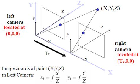
《Learning OpenCV》中对于 Translation 和 Rotation 的图示是这样的:

示例代码:
cv::Matx33d K1, K2, R;
cv::Vec3d T;
cv::Vec4d D1, D2;

int flag = 0;
flag |= cv::fisheye::CALIB_RECOMPUTE_EXTRINSIC;
flag |= cv::fisheye::CALIB_CHECK_COND;
flag |= cv::fisheye::CALIB_FIX_SKEW;

cv::fisheye::stereoCalibrate(
        obj_points_, img_points_l_, img_points_r_,
        K1, D1, K2, D2, img_size_, R, T,
        flag, cv::TermCriteria(3, 12, 0));
3. 双目矫正
双目矫正 主要包括两方面:畸变矫正 和 立体矫正 。
利用 OpenCV的函数,主要分为
- stereoRectify
- initUndistortRectifyMap
- remap
stereoRectify
根据双目标定的结果 K 1 , K 2 , D 1 , D 2 , R , t K_1, K_2, D_1, D_2, R, t K1,K2,D1,D2,R,t,利用 OpenCV函数 stereoRectify,计算得到如下参数
- 左目 矫正矩阵(旋转矩阵) R 1 R_1 R1 (3x3)
- 右目 矫正矩阵(旋转矩阵) R 2 R_2 R2 (3x3)
- 左目 投影矩阵 P 1 P_1 P1 (3x4)
- 右目 投影矩阵 P 2 P_2 P2 (3x4)
- disparity-to-depth 映射矩阵 Q Q Q (4x4)
其中,
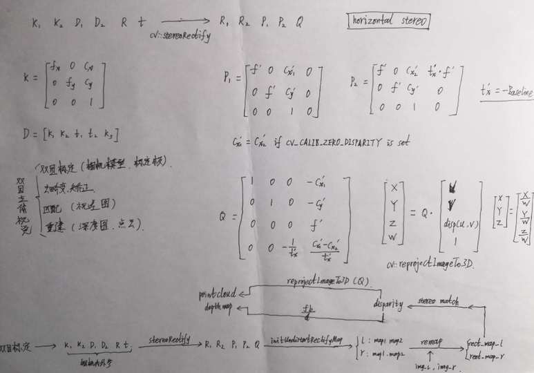
左右目投影矩阵(horizontal stereo, c x 1 ′ = c x 2 ′ {c_x}_1'={c_x}_2' cx1′=cx2′ if CV_CALIB_ZERO_DISPARITY is set)
P 1 = [ f ′ 0 c x 1 ′ 0 0 f ′ c y ′ 0 0 0 1 0 ] P_1 = \begin{bmatrix} f' & 0 & {c_x}_1' & 0 \\ 0 & f' & c_y' & 0 \\ 0 & 0 & 1 & 0 \end{bmatrix} P1=⎣⎡f′000f′0cx1′cy′1000⎦⎤
P 2 = [ f ′ 0 c x 2 ′ t x ′ ⋅ f ′ 0 f ′ c y ′ 0 0 0 1 0 ] P_2 = \begin{bmatrix} f' & 0 & {c_x}_2' & t_x' \cdot f' \\ 0 & f' & c_y' & 0 \\ 0 & 0 & 1 & 0 \end{bmatrix} P2=⎣⎡f′000f′0cx2′cy′1tx′⋅f′00⎦⎤
where
t x ′ = − B t_x' = -B tx′=−B
disparity-to-depth 映射矩阵
Q = [ 1 0 0 − c x 1 ′ 0 1 0 − c y ′ 0 0 0 f ′ 0 0 − 1 t x ′ c x 1 ′ − c x 2 ′ t x ′ ] Q = \begin{bmatrix} 1 & 0 & 0 & -{c_x}_1' \\ 0 & 1 & 0 & -c_y' \\ 0 & 0 & 0 & f' \\ 0 & 0 & -\frac{1}{t_x'} & \frac{ {c_x}_1'-{c_x}_2'}{t_x'} \end{bmatrix} Q=⎣⎢⎢⎡10000100000−tx′1−cx1′−cy′f′tx′cx1′−cx2′⎦⎥⎥⎤
通过 P 2 P_2 P2 可计算出 基线 长度:
baseline = B = − t x ′ = − P 2 ( 03 ) f ′ \begin{aligned} \text{baseline} = B = - t_x' = - \frac{ {P_2}_{(03)} }{f'} \end{aligned} baseline=B=−tx′=−f′P2(03)
示例代码:
cv::Mat R1, R2, P1, P2, Q;
cv::fisheye::stereoRectify(
        K1, D1, K2, D2, img_size_, R, T,
        R1, R2, P1, P2, Q,
        CV_CALIB_ZERO_DISPARITY, img_size_, 0.0, 1.1);
CameraInfo DKRP
参考:sensor_msgs/CameraInfo Message
-
D: distortion parameters.
- For “plumb_bob”, the 5 parameters are: (k1, k2, t1, t2, k3)
-
K: Intrinsic camera matrix for the raw (distorted) images.
- Projects 3D points in the camera coordinate frame to 2D pixel coordinates using the focal lengths (fx, fy) and principal point (cx, cy).
K = [ f x 0 c x 0 f y c y 0 0 1 ] \mathbf{K} = \begin{bmatrix} f_x & 0 & c_x \\ 0 & f_y & c_y \\ 0 & 0 & 1 \end{bmatrix} K=⎣⎡fx000fy0cxcy1⎦⎤
- Projects 3D points in the camera coordinate frame to 2D pixel coordinates using the focal lengths (fx, fy) and principal point (cx, cy).
-
R: Rectification matrix (stereo cameras only).
- A rotation matrix aligning the camera coordinate system to the ideal stereo image plane so that epipolar lines in both stereo images are parallel.
- For monocular cameras R = I \mathbf{R} = \mathbf{I} R=I
-
P: Projection/camera matrix.
- For monocular cameras
P = [ f x 0 c x 0 0 f y c y 0 0 0 1 0 ] \mathbf{P} = \begin{bmatrix} f_x & 0 & c_x & 0 \\ 0 & f_y & c_y & 0 \\ 0 & 0 & 1 & 0 \end{bmatrix} P=⎣⎡fx000fy0cxcy1000⎦⎤ - For a stereo pair, the fourth column [Tx Ty 0]’ is related to the position of the optical center of the second camera in the first camera’s frame. We assume Tz = 0 so both cameras are in the same stereo image plane.
- The first camera
P = [ f x ′ 0 c x ′ 0 0 f y ′ c y ′ 0 0 0 1 0 ] \mathbf{P} = \begin{bmatrix} f_x' & 0 & c_x' & 0 \\ 0 & f_y' & c_y' & 0 \\ 0 & 0 & 1 & 0 \end{bmatrix} P=⎣⎡fx′000fy′0cx′cy′1000⎦⎤ - The second camera
P = [ f x ′ 0 c x ′ − f x ′ ⋅ B 0 f y ′ c y ′ 0 0 0 1 0 ] \mathbf{P} = \begin{bmatrix} f_x' & 0 & c_x' & -f_x' \cdot B \\ 0 & f_y' & c_y' & 0 \\ 0 & 0 & 1 & 0 \end{bmatrix} P=⎣⎡fx′000fy′0cx′cy′1−fx′⋅B00⎦⎤
- The first camera
- Given a 3D point [ X Y Z ] ′ [X Y Z]' [XYZ]′, the projection ( x , y ) (x, y) (x,y) of the point onto the rectified image is given by:
[ u v w ] = P ⋅ [ X Y Z 1 ] , { x = u w y = v w \begin{bmatrix} u \\ v \\ w \end{bmatrix} = \mathbf{P} \cdot \begin{bmatrix} X \\ Y \\ Z \\ 1 \end{bmatrix} , \quad \begin{cases} x = \frac{u}{w} \\ y = \frac{v}{w} \end{cases} ⎣⎡uvw⎦⎤=P⋅⎣⎢⎢⎡XYZ1⎦⎥⎥⎤,{x=wuy=wv
- For monocular cameras
initUndistortRectifyMap
左右目 分别利用 OpenCV函数 initUndistortRectifyMap 计算 the undistortion and rectification transformation map,得到
- 左目map: m a p 1 l , m a p 2 l map^l_1, map^l_2 map1l,map2l
- 右目map: m a p 1 r , m a p 2 r map^r_1, map^r_2 map1r,map2r
示例代码:
cv::fisheye::initUndistortRectifyMap(K1, D1, R1, P1, img_size, CV_16SC2, rect_map_[0][0], rect_map_[0][1]);
cv::fisheye::initUndistortRectifyMap(K2, D2, R2, P2, img_size, CV_16SC2, rect_map_[1][0], rect_map_[1][1]);
Remap
左右目 分别利用 OpenCV函数 remap 并根据 左右目map 对左右目图像进行 去畸变 和 立体矫正,得到 左右目矫正图像
示例代码:
cv::remap(img_l, img_rect_l, rect_map_[0][0], rect_map_[0][1], cv::INTER_LINEAR);
cv::remap(img_r, img_rect_r, rect_map_[1][0], rect_map_[1][1], cv::INTER_LINEAR);
4. 立体匹配
根据双目矫正图像,通过 BM或SGM等立体匹配算法 对其进行立体匹配,计算 视差图
视差计算
通过 OpenCV函数 stereoBM (block matching algorithm),生成 视差图(Disparity Map) (CV_16S or CV_32F)
disparity map from stereoBM of OpenCV :
It has the same size as the input images. When disptype == CV_16S, the map is a 16-bit signed single-channel image, containing disparity values scaled by 16. To get the true disparity values from such fixed-point representation, you will need to divide each disp element by 16. If disptype == CV_32F, the disparity map will already contain the real disparity values on output.
So if you’ve chosen disptype = CV_16S during computation, you can access a pixel at pixel-position (X,Y) by: short pixVal = disparity.at, while the disparity value is float disparity = pixVal / 16.0f;; if you’ve chosen disptype = CV_32F during computation, you can access the disparity directly: float disparity = disparity.at
- Disparity Map
- Disparity map post-filtering
5. 三维重建
(1)算法1:根据视差图,利用 f ′ f' f′ 和 B B B 通过几何关系计算 深度值,并利用相机内参计算 三维坐标
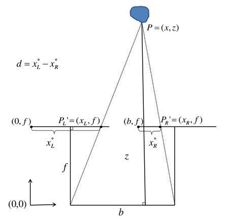
根据上图相似三角形关系,得
Z B = Z − f B − d w ⟹ Z = B f d w \frac{Z}{B} = \frac{Z-f}{B-d_w} \quad \Longrightarrow \quad Z = \frac{Bf}{d_w} BZ=B−dwZ−f⟹Z=dwBf
其中, f f f 和 d w d_w dw 分别为 成像平面的焦距和视差,单位均为 物理单位,将其转换为 像素单位,上式写为
Z = B f ′ d p Z = \frac{B f'}{d_p} Z=dpBf′
其中,
d p = ( O r − u r ) + ( u l − O l ) = ( u l − u r ) + ( O r − O l ) d_p = (O_r - u_r) + (u_l - O_l) = (u_l - u_r) + (O_r - O_l) dp=(Or−ur)+(ul−Ol)=(ul−ur)+(Or−Ol)
最终,深度计算公式如下,通过遍历图像可生成 深度图
Z = depth = B ⋅ f ′ d p with d p = disp ( u , v ) + ( c x 2 ′ − c x 1 ′ ) Z = \text{depth} = \frac{B \cdot f'}{d_p} \quad \text{with} \quad d_p = \text{disp}(u,v) + ({c_x}_2' - {c_x}_1') Z=depth=dpB⋅f′withdp=disp(u,v)+(cx2′−cx1′)
根据 小孔成像模型,已知 Z Z Z 和 相机内参 可计算出 三维点坐标,从而可生成 三维点云
{ Z = depth = f ′ ⋅ B d p X = u − c x 1 ′ f ′ ⋅ Z Y = v − c y ′ f ′ ⋅ Z 或 { bd = B d p Z = depth = f ′ ⋅ bd X = ( u − c x 1 ′ ) ⋅ bd Y = ( u − c y ′ ) ⋅ bd \begin{aligned} \begin{cases} Z = \text{depth} = \frac{f' \cdot B}{d_p} \\ X = \frac{u-{c_x}_1'}{f'} \cdot Z \\ Y = \frac{v-{c_y}'}{f'} \cdot Z \end{cases} \end{aligned} \text{或} \begin{aligned} \begin{cases} \text{bd} = \frac{B}{d_p}\\ Z = \text{depth} = f' \cdot \text{bd} \\ X = (u-{c_x}_1') \cdot \text{bd} \\ Y = (u-{c_y}') \cdot \text{bd} \end{cases} \end{aligned} ⎩⎪⎪⎨⎪⎪⎧Z=depth=dpf′⋅BX=f′u−cx1′⋅ZY=f′v−cy′⋅Z或⎩⎪⎪⎪⎨⎪⎪⎪⎧bd=dpBZ=depth=f′⋅bdX=(u−cx1′)⋅bdY=(u−cy′)⋅bd
其中, disp ( u , v ) \text{disp}(u,v) disp(u,v) 代表 视差图 坐标值
(2)算法2:根据视差图,利用 Q Q Q 矩阵 计算 三维点坐标(reprojectImageTo3D)
[ X ′ Y ′ Z ′ W ] = Q ⋅ [ u v disp ( u , v ) 1 ] \begin{bmatrix} X' \\ Y' \\ Z' \\ W \end{bmatrix} = Q \cdot \begin{bmatrix} u \\ v \\ \text{disp}(u,v) \\ 1 \end{bmatrix} ⎣⎢⎢⎡X′Y′Z′W⎦⎥⎥⎤=Q⋅⎣⎢⎢⎡uvdisp(u,v)1⎦⎥⎥⎤
最终,三维点坐标为
[ X Y Z ] = [ X ′ W Y ′ W Z ′ W ] \begin{bmatrix} X \\ Y \\ Z \end{bmatrix} = \begin{bmatrix} \frac{X'}{W} \\[2ex] \frac{Y'}{W} \\[2ex] \frac{Z'}{W} \end{bmatrix} ⎣⎡XYZ⎦⎤=⎣⎢⎢⎢⎡WX′WY′WZ′⎦⎥⎥⎥⎤
深度图 图像类型
- 单位meter --> 32FC1
- 单位millimeter --> 16UC1
总结