滤波器入门RLC电路BSF
滤波器入门RLC电路BSF
Abstract
A filter for attenuating 10kHZ signal from 1kHZ signal is needed. We use RLC circuit as a band stop filter to achieve this and use oscilloscope and frequency analyzer to observe the result .We get -41.617dB gain and -40.2dB gain for 10kHZ signal in simulation and real circuit respectively.
Introduction
In this experiment ,we are asked to design a filter .The useful band width is 0HZ-1kHZ, but it is contaminated by an undesired 10kHZ harmonic (sinusoidal) signal. We need to design a filter that let pass through the useful signal without attenuating to it and attenuates the 10kHZ harmonic signal by at least 40dB(0.01).
Methodology
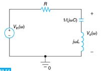
In order to successfully attenuates the 10kHZ harmonic signal and preserve useful signal ,we decide to use RLC series circuit as a BSF.
We choose this circuit because it can significantly attenuates signal in a certain frequency width without attenuating other frequency signals.
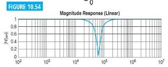
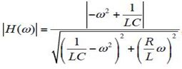
To get the ideal value for components in our circuit ,we first get formula of gain of our circuit through voltage divider rules in circuit. And we can kwon from this formula that the null frequency is w=2\pi f=\frac{1}{\sqrt{LC}}=20000π\approx63245.55 rad/s .And we choose R=5000Ω, L=50mH,C=5nF.
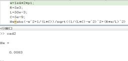
Then we calculate the theoretical value in MATLAB and get that the gain of the unwanted 10kHZ as less than 0.01(0.0083) ,it means that the attenuation result is more than 40dB.
After getting this result we decide to simulate the circuit in PSPice and also construct the circuit on breadboard to better prove our result.

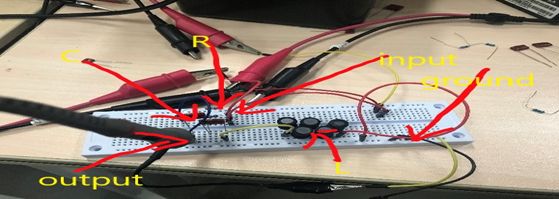
(In this circuit ,we connect two sinusoid signal sources in series so that we can get a 1kHZ signal with 10kHZ signal as a contamination. The input of the circuit is between the signal source and R1, the output of circuit is between R1 and C1,the ground is obvious with its symbol on the circuit. XSCI is oscilloscope, and XBPI is frequency analyzer )
Results and Discussion
In PSPice we get the simulation result as below:
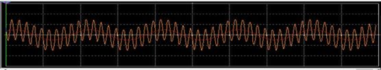
(Orange line is the input signal and red line is the signal after attenuation).

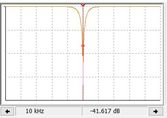
(This is the result of the frequency analyzer XBPI ,we can see that for signal near 1kHZ ,its gain is -0.111 dB which is small enough, and attenuation for 10kHZ signal is 41.617dB which satisfy the requirement successfully.)

And this is result of the circuit we construct on breadboard .Regretfully ,there is no frequency analyzer in lab, so we just can use the P-P value to roughly calculate the gain of the output wave. We get that gain of the 1kHZ signal is about-7dB ,and the gain of the 10kHZ signal is about -40.2dB.
The circuit on bread board obviously work less efficiently than that in simulation. Through discussion ,we think this is mainly because the resistance of the inductance are not negligible in real circuit.
Conclusions
Our problem is to construct a filter circuit to attenuate 10kHZ signal from 1kHZ signal .To handle this we use a series RLC circuit as a band stop filter . To compare the difference of the input signal and output signal ,we use oscilloscope with two input to illustrate the waveform. And to know the effect of attenuation we use a frequency analyzer to analyze the output signal ,and get a proposed result in simulation .However ,in circuit constructed on bread board the error is much bigger and this may because the resistance in inductance or error in the value of the components.