基于VHDL奇偶校验发生器程序设计
基于VHDL奇偶校验发生器程序设计
知识点梳理:
GENERIC参数的映射
在元件进行实例化时如果需要传递参数,则须使用关键字generic,来进行generic参数的映射。语法结构:
label:元件名称 generic map(参数列表) port map (端口列表);--进行generic参数的说明和传递
通用属性语句(GENERIC)的一种用法
用于指定常规参数,所指定的参数是静态的,方便设计人员进行参数修改,可增加代码的灵活性和可重用性。
-
generic语句须在ENTITY中进行声明;
-
generic语句所指定的参数是全局的,不仅可以在ENTITY 内部使用,还可以在后面的整个设计中使用。
-
主要用来为设计实体指定参数,如端口宽度、器件延时等;
-
语法结构:
   GENERIC (参数名:参数类型:=参数值);
元件声明的两种位置(或两种方法)
a. 在主代码段中声明

b. 在package中声明

案例分析:
奇偶校验发生器:带有GENERIC参数的元件的实例化
功能描述:
1、输入矢量的宽度比输出矢量的宽度少一位;输出矢量的其它位由输入矢量直接赋值。
2、功能固定,规格不固定,可以设计成通用构造体。
3、需要统计输入矢量中‘1’的个数,当输入矢量中‘1’的个数为奇数时则插入一个‘1’,为偶数时则插入一个‘0’。

设计方案:
具有较强的通用性,将输入矢量的宽度n作为generic参数加以传递;将代码元件化。
软件说明:
ModelSimSetup-13.1.0.162,QuartusSetup-13.1.0.162。
建立工程:
第一步:打开Quartus软件。
第二步:点击New Project Wizard -> next.
第三步:选择工程文件的存放位置,输入工程名 -> next -> next。
第四步:在family栏选择芯片型号-Cyclone IV E,在Name栏选择EP4CE115F29C7,选择完之后点击next。(如果不进行硬件调试时,此处默认即可)
第五步:检查工程有没有建错,点击完成。如下图:

程序设计:
方法一:(在包集中声明元件)
设计步骤:
- 编写几个基本组成模块(parity_gen)的.vhd文件;
- 创建一个包集文件(my_components.vhd),在该包集中将这几个基本组成模块声明为元件;
- 在主代码中use该包集; 在主代码中实例化这些元件。
全加器顶层文件设计:
--文件名:my_code_1.vhd 应与工程名保持一致:
------主文件my_code_1.vhd----------
library ieee;
use ieee.std_logic_1164.all;
use work.my_components.all;
entity my_code_1 is
    GENERIC (n: positive :=2);   --2 will overwrite 7 ;
    port (inp: in bit_vector (n downto 0);
            outp: out bit_vector (n+1 downto 0));
end my_code_1;
architecture my_arch  of my_code_1 is
begin
   c1: parity_gen generic map (n) port map (inp, outp);
end my_arch;
------------------------------------------------
包集声明元件:
------包集文件my_components.vhd----------
library ieee;
use ieee.std_logic_1164.all;
package my_components is
      -------------元件在包集中的声明-------
     ----------------声明元件parity_gen-------------
       component parity_gen is
             generic (n: positive) ;
             port (input: in bit_vector (n downto 0);
                      output: out bit_vector (n+1 downto 0));
        end component;--对应文件parity_gen.vhd
---------------------------------------------------
end my_components;
元件模块文件实现:
--文件名:parity_gen.vhd
------包集文件parity_gen.vhd----------
library ieee;
use ieee.std_logic_1164.all;
entity parity_gen is
    GENERIC (n: integer :=7);   --default is 7 ;
    port (input: in bit_vector (n downto 0);
            output: out bit_vector (n+1 downto 0));
end parity_gen;
architecture parity  of parity_gen is
begin
    process (input)
         variable temp1: bit;
         variable temp2: bit_vector (output'range);
    begin
          temp1:='0';
          for i IN input'range loop
               temp1:=temp1 XOR input(i);
               temp2(i):=input(i);
          end loop;
          temp2(output'high):=temp1;
          output<=temp2;
     end process;
end parity;
方法二:(在主代码中声明元件)
设计步骤:
- 编写几个基本组成模块(parity_gen)的.vhd文件;
- 在主代码中将这几个基本组成模块声明为元件;
- 在主代码中实例化这些元件。
全加器顶层文件设计:
--文件名:my_code.vhd 应与工程名保持一致:
------主文件my_code.vhd----------
library ieee;
use ieee.std_logic_1164.all;
entity my_code is
    GENERIC (n: positive :=2);   --2 will overwrite 7 ;
    port (inp: in bit_vector (n downto 0);
            outp: out bit_vector (n+1 downto 0));
end my_code;
architecture my_arch  of my_code is
----------------声明元件parity_gen-------------
       component parity_gen is
             generic (n: positive) ;
             port (input: in bit_vector (n downto 0);
                      output: out bit_vector (n+1 downto 0));
        end component;
---------------------------------------------------
begin
   c1: parity_gen generic map (n) port map (inp, outp);
end my_arch;
------------------------------------------------
元件模块文件实现:
--文件名:parity_gen.vhd
------包集文件parity_gen.vhd----------
library ieee;
use ieee.std_logic_1164.all;
entity parity_gen is
    GENERIC (n: integer :=7);   --default is 7 ;
    port (input: in bit_vector (n downto 0);
            output: out bit_vector (n+1 downto 0));
end parity_gen;
architecture parity  of parity_gen is
begin
    process (input)
         variable temp1: bit;
         variable temp2: bit_vector (output'range);
    begin
          temp1:='0';
          for i IN input'range loop
               temp1:=temp1 XOR input(i);
               temp2(i):=input(i);
          end loop;
          temp2(output'high):=temp1;
          output<=temp2;
     end process;
end parity;
文件仿真(这里采用modelsim仿真波形):
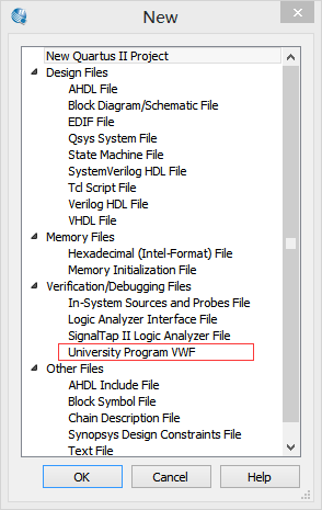
- 选择File-> New -> Verification/Debugging Files ->University Program VWF。
2.打开测试文件。(右键点击添加端口,对输入信号初始化,赋值。)

3.仿真结果:

逻辑电路图:
显示编译成功后,选择菜单栏 Tools –>Netlist Viewers –>RTL Viewer 显示逻辑电路图
