Pynq_Z2利用AXI_Lite从PS端读取PL端的数据
1. 软件平台
vivado2019.1
2. 硬件平台
PYNQ_Z2
3. 具体实现流程
能需要做这一步,证明对vivado和IP核的自定义已经比较熟悉,如果没有可以看这。自定义IP核流程
操作蛮挺简单的 ,但是我一开始也踏了好多坑。
首先,编辑一个数据生成器。(第一次操作建议使用一个固定的值,比如:reg [15:0]data_out = 4095;这样可以避免很多问题)
module data_gen(
    input clk_n,rst_n,
    output reg [15:0]data
    );
    parameter count_end = 8'd100;
    reg [8:0]count;
always @(posedge clk_n or negedge rst_n)
begin
    if(!rst_n)
    begin
        count <= 0;
        data <= 0;
    end
    else
        begin
            count <= count + 1'b1;
            if(count > 8'd99)
             begin
                count <= 0;
                data <= data+1'b1;
                if(data>=16'd65535)
                    data <= 0;
             end
        end
end
endmodule
采用的时钟为100Mhz,产生的数据变化率为1MHz。
现在看到这里

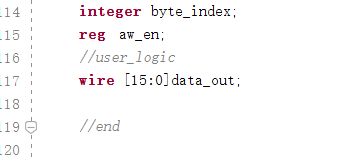
在这里添加一个wire变量
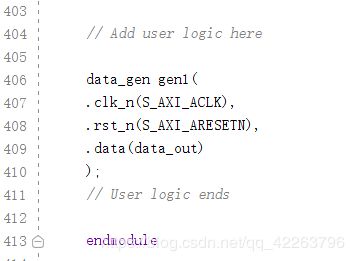
在这里调用刚刚编辑的数据产生模块
如果想了解清楚一点可以好好看看这个文件注释,这个文件包括读和写部分,把目光看到读数据部分
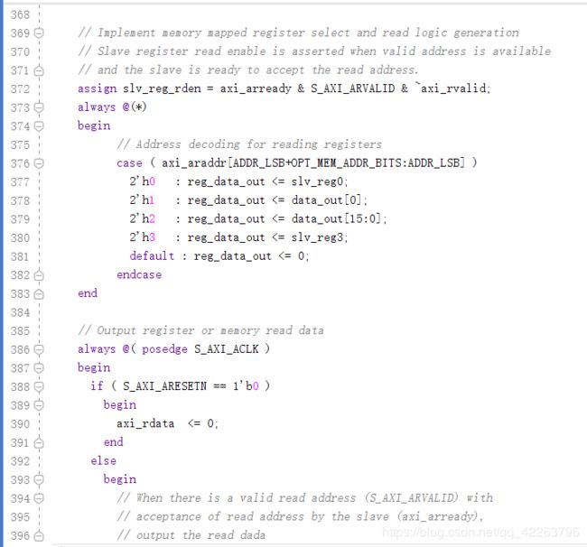
这里将slv_reg1替换为data_out[0](输出第一位),
将slv_reg2替换为data_out[15:0](输出生成的数据)

从这里不难发现,是根据地址来读取数据,具体怎么来的,这里不做分析。
然后,保存,综合验证,查看是否有问题。然后打包IP核(如果有经验就不用看了自定义IP核流程)
这样一个IP核就弄好了,然后是建立Block design,用SDK读取数据了
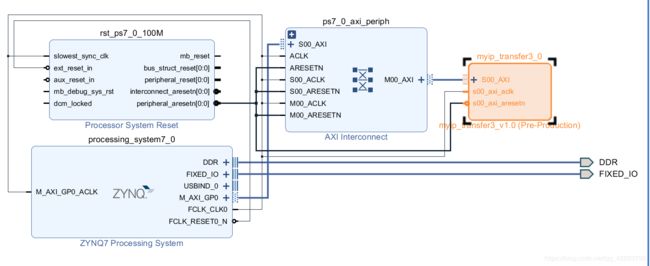
这里没有用其他的AXI通道口,用的是普通的AXI速度较慢
SDK部分代码如下
#include
#include "platform.h"
#include "xil_printf.h"
/* Include Files */
#include "xparameters.h"
#include "xil_io.h"
#include "xstatus.h"
/* Definitions */
#define printf xil_printf							/* smaller, optimised printf */
/*
 *
 */
u32 flag0= 4095;
u32 flag1= 32767;

#define  data0 0x43c00000
#define  data1 0x43c00004
#define  data2	0x43c00008
#define  data3  0x43c0000C
u16 data[8192];
int i=0;
int main()
{
    init_platform();
    print("Hello World\n\r");

    cleanup_platform();
	/* Execute the pwm output. */
    while(1)
    {

    	data[i]=Xil_In32(data2);
    	i++;
    	if(i>=8192)
    		i=0;
    	 printf("i=%d->->->data=%d\n\r",i,data[i]);

    }

    return 0;
}
data0 -data4对应那AXI_lite的寄存器
下载运行,就可以在windows->view->expresion看到读到的数据了