Quartus 调用PLL IP核仿真
- Quartus 调用PLL IP核仿真
- 生成PLL IP核
- 编写Test Bench文件
Quartus 调用PLL IP核仿真
本文简要介绍在Quartus中调用PLL IP核进行仿真。PLL(Phase Lock Loop)是锁相环,简单地说就是能够将一种频率的信号转换为另一种频率的信号。本文主要介绍PLL IP核的产生,Test Bench文件的编写和对IP核的仿真。
运行环境:
- Quartus:Quartus Prime Version 16.0.0 in Linux
- Simulation: ModleSim-Altera
生成PLL IP核
首先新建一个空的项目,此处较为简单,省略。这里的项目名称为
pll_simulation_test,如下图。编写顶级文件。因为是空的项目,所以没有包含顶级文件,编译的话会出错。新建一个Verilog HDL File,输入以下简单的内容:
module pll_simulation_test(
        input wire clk  //clock signal
);
endmodule 找到Altera PLL,并点击“Add”,弹出如下窗口:
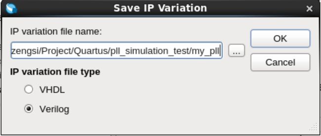
给PLL IP核取名字,这里是my_pll,点击OK。出现IP核的设置界面。
在这里我取消勾选“Enable locked output port”,即让输出只有一个。另外将“Reference Clock Frequency”设置为25.0MHz。点“Finish”完成。
“Exit”之后会弹出一个对话框,询问是否将my_pll.qip文件添加到工程。这里选择”Yes”。
至此,PLL IP Core产生完成。
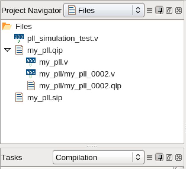
Tip:你可以将项目导航切换到Files,看看是否有以下文件。


双击“my_pll.v”可以看到PLL IP 核的声明。
编写Test Bench文件
接下来我们开始编写一个简单测试文件。
首先新建一个Verilog HDL Files,取名为my_pll_tb.v。
  // File: my_pll_tb.v
  // Author: ZHUO Zengsi
  // Date: 2016-10-20
  // Function: This test bench file is to test the simulation of
  // PLL IP Core.

  `timescale 1ns/1ps

  module my_pll_tb();

    reg clk;                  // the reference clock signal, 25MHz
    reg rst;                  // the reset signal
    reg unsigned [3: 0] cnt;      // the count of clk, maximum is 15
    wire clk_out;         // the output signal with 100MHz

    my_pll init_my_pll_0(
        .refclk(clk),     // refclk.clk
        .rst(rst),        // reset.reset
        .outclk_0(clk_out)// outclk0.clk
    );

    initial
    begin
        clk = 1'b0;       // make initial value be 0
        rst = 1'b1;   // make initial value be 1
        cnt = 4'b0001;    // make initial value be 1
        #20 rst = 1'b0;   // after 20ns reset finished
    end

    always #20 clk = ~clk;   //reverse the signal every 20ns.

    always @(posedge clk)
    begin
        cnt <= cnt + 1;   // when the clk rise, cnt will increment 1
        if (cnt == 0)     // if cnt is 16, stop the simulation.
            $stop();
    end

  endmodule
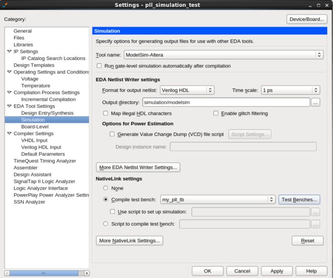
在“Tool Name”中选择“ModelSim-ALtera”,选中“Compile test bench”,按照我们写的Test Bench文件来仿真,所以点击“Test Benches”。出现以下界面。
点击“New”新建一个Test Bench,如下图。
这里输入“Test bench name”为my_pll_tb,并在“File ame”中选中刚才编写的my_pll_tb.v文件。
然后“OK”回到上一个界面,再“OK”回到设置界面。
此时,在“Compile test bench”中出现刚下新建的Test Bench了。点击“OK”,仿真环境搭建完成。
## 仿真结果 接下来我们开始仿真。点击“Tools -> Run Simulation Tool -> RTL Simulation”开始仿真,仿真出现如下结果。仿真的结果中出现四个信号,其中分别为时钟信号clk,重置信号rst,计数信号cnt以及输出信号clk_out,如下图。
在Test Bench文件中,我们延迟了20ns之后将重置信号置为0,这时候PLL开始正常运行。输入信号clk的频率为25Mhz,输出信号clk_out的频率为100MHz。当cnt的值为16时,停止仿真。总的仿真时间为620ns。


