51单片机入门 - SPI协议与应用实验
关注【电子开发圈】微信公众号,一起学习吧!
电子DIY、Arduino、51单片机、STM32单片机、FPGA……
电子百科、开发技术、职业经验、趣味知识、科技头条、设备拆机……
点击链接,免费下载100G+电子设计学习资料!
http://mp.weixin.qq.com/mp/homepage?__biz=MzU3OTczMzk5Mg==&hid=7&sn=ad5d5d0f15df84f4a92ebf72f88d4ee8&scene=18#wechat_redirect
简介:
- 串行外围设备接口
- 全双工三线同步,可以同时发出和接收串行数据
- 采用主从(Master Slave)架构,支持多Slave模式应用,一般仅支持单Slave
- 时钟由Master控制,在时钟移位脉冲下,数据按位传输,高位在前,低位在后
- 目前应用中可以达到几Mbps的水平
- 优点:与普通的串行设备相比,可以按位传输,甚至可以暂停。当没有时钟跳变时,从设备不采集和传送数据。不需要寻址操作。全双工通信。
- 缺点:没有应答机制确认。
特点:
- 提供频率可编程时钟
- 发送结束、中断标志;写冲突保护
- 总线竞争保护
- SPI总线工作的4种工作方式中,使用最广泛的是SPI0和SPI3方式
- - - - - - - - - - - - - - - - - - - - - - - - - - - - - - - - - - - - - - - - - - - - - - - - - - - - - - - - - - - - - - - - - - - - - - - - - -
信号线情况:
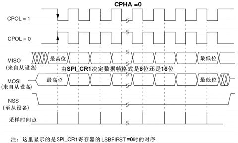
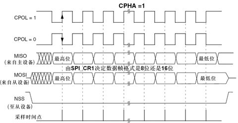
- SCLK提供时钟脉冲,SDI/SDO基于此脉冲按位传输。当处于上升沿模式时,输出:通过SDO线在时钟上升沿时输出,在紧接着的下降沿被读取。输入同理。
- SS/CS是片选信号线,只有片选信号为使能信号时,对芯片的操作才有效,所以可以在同一总线上连接多个SPI设备
- SDI:slave → master,从机要发送给主机的数据
- SDO:master → slave,主机要发送给从机的数据
- - - - - - - - - - - - - - - - - - - - - - - - - - - - - - - - - - - - - - - - - - - - - - - - - - - - - - - - - - - - - - - - - - - - - - - - - -
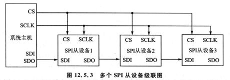
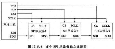
连接方式:
- 级联方式:此时所有设备的CS端都连在一起,只要选中一个设备,则全选。可以作为一个设备进行处理。
- 独立连接方式:设备独立操作,为被选通的从设备均处于高阻隔离状态。
- - - - - - - - - - - - - - - - - - - - - - - - - - - - - - - - - - - - - - - - - - - - - - - - - - - - - - - - - - - - - - - - - - - - - - - - - -
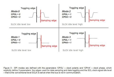
工作模式:
| SPI模式 |
CPOL极性 |
CPHA相位 |
说明 |
| 0 |
0 |
0 |
第一个边沿上升沿 |
| 1 |
0 |
1 |
第二个边沿下降沿 |
| 2 |
1 |
0 |
第一个边沿下降沿 |
| 3 |
1 |
1 |
第二个边沿上升沿 |
CPOL=0:SCLK有效时为高电平(active-high)
CPOL=1:SCLK有效时为低电平(active-low)
CPHA=0:表示第一个边沿
CPHA=1:表示第二个边沿
Toggling edge为切换边沿,输出信号
Sampling edge为采样边沿,输入信号
时序图:
- - - - - - - - - - - - - - - - - - - - - - - - - - - - - - - - - - - - - - - - - - - - - - - - - - - - - - - - - - - - - - - - - - - - - - - - - -
SPI协议举例
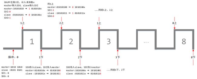
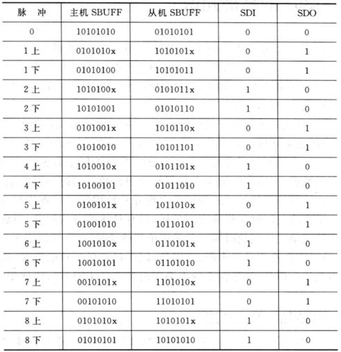
- 主机8位寄存器存放的是1010 1010,从机存放的是0101 0101,将主从机数据交换
- SDI:slave → master
- SDO:master → slave
- 上升沿发送、下降沿接收
初始化就绪状态:
- 主机SBUFF = 1010 1010
- 从机SBUFF = 0101 0101
操作过程:如图所示,经过8个脉冲后,master和slave数据交换
SPI的8个时钟周期的数据:
————————————————————————————————————————————
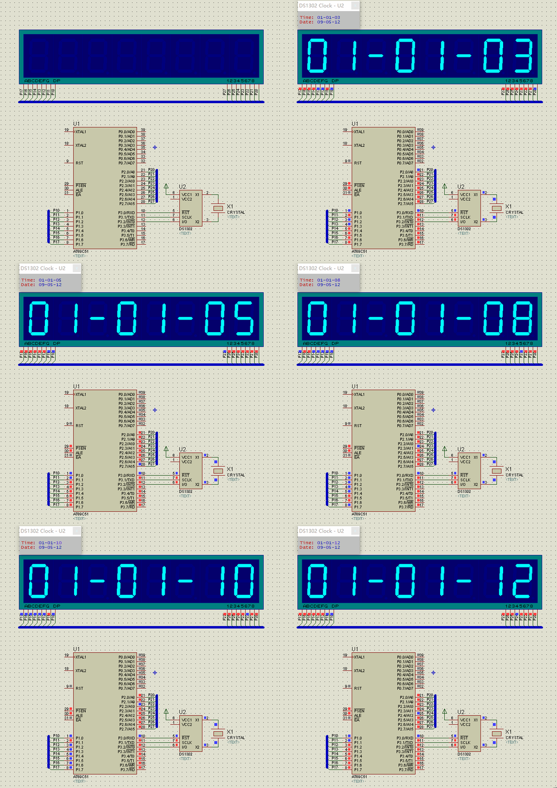
基于SPI协议,DS1302显示时钟实例
- - - - - - - - - - - - - - - - - - - - - - - - - - - - - - - - - - - - - - - - - - - - - - - - - - - - - - - - - - - - - - - - - - - - - - - - - -
实现效果:
实现代码:
#include
typedef unsigned char uchar;
typedef unsigned int uint;
//写操作控制字节,D7=1,D0=0
uchar code write_address[] =
{
    //秒,分,小时,日,月,星期,年
    0x80, 0x82, 0x84, 0x86, 0x88, 0x8a, 0x8c
};
//读操作,D7=1,D0=1,地址同写操作
uchar code read_address[] =
{
    0x81, 0x83, 0x85, 0x87, 0x89, 0x8b, 0x8d
};
uchar code table[] =
{
    //0,1,2,3,4,5,6,7,8,9
    0xfc, 0x60, 0xda, 0xf2, 0x66, 0xb6, 0xbe, 0xe0, 0xfe, 0xf6
};
//dat1和dat2存放读出来的时间,初始值写入12年5月9日1时1分1秒,dat1存放1234位,dat2存放567位
uchar dat1[] = {0x01, 0x01, 0x01, 0x09, 0x05, 0x02, 0x12};
uchar dat2[] = {0x01, 0x01, 0x01, 0x09, 0x05, 0x02, 0x12};
sbit rst = P3 ^ 0;
sbit scl = P3 ^ 1;
sbit sda = P3 ^ 2;
sbit ACC7 = ACC ^ 7;
void Delay(uint m)
{
    while(m--);
}
/* SPI协议操作,读字节 */
uchar ReadByte()
{
    uchar i;
    for (i = 0; i < 8; ++i)
    {
        ACC = ACC >> 1; //累加器左移1位,补上未知数x
        ACC7 = sda; //从sda引脚写入ACC最高位
        scl = 1;
        scl = 0; //时钟下降沿读入
    }
    return ACC;
}
/* SPI协议操作,写字节 */
void WriteByte(uchar byte)
{
    uchar i;
    for (i = 0; i < 8; ++i)
    {
        byte >>= 1; //byte左移1位存入CY
        scl = 0;
        sda = CY; //从CY移入sda,发送给DS102
        scl = 1; //时钟上升沿写入
    }
}
void Write1302(uchar address, uchar dat) //写地址子程序
{
    rst = 0;
    scl = 0;
    rst = 1; //rst上升沿开始写数据
    WriteByte(address); //先写入地址控制字节
    WriteByte(dat); //再写入数据字节
    rst = 0;
}
uchar Read1302(uchar address)
{
    uchar temp;
    rst = 0;
    scl = 0;
    rst = 1; //读过程中保持rst高电平状态
    WriteByte(address | 0x01); //写入地址并置R/W位为1(读)
    temp = ReadByte(); //在单片机写入命令字节的最后一位的第一个下降沿处即读出数据
    scl = 1;
    rst = 0;
    return temp;
}
void SetRST()
{
    uchar i;
    Write1302(0x8e, 0x00); //向10001110写保护寄存器,写入指令0x00
    for (i = 0; i < 7; ++i)
        Write1302(write_address[i], dat1[i]); //从秒到年各寄存器写入对应初始值
    Write1302(0x8e, 0x80); //向写保护寄存器,写入数据0x80
}
void ReadTime()
{
    uchar i, temp1, temp2, temp3;
    temp3 = 0x80; //temp3存放时间寄存器地址
    for (i = 0; i < 7; ++i) //分别读出秒分小时日月星期年
    {
        temp1 = Read1302(temp3);
        temp2 = temp1;
        dat1[i] = (temp1 >> 1) & 0x0f; //读出的数据1234位存入dat1,屏蔽其他位
        dat2[i] = (temp2 >> 5) & 0x07; //读出的数据567位存入dat2,屏蔽其他位
        temp3 = temp3 + 0x02; //下一个寄存器地址
    }
}
void main()
{
    rst = 0;
    SetRST(); //时钟建立
    while(1)
    {
        ReadTime(); //读时间
        P2 = 0xfe;
        P1 = table[dat1[0] % 10];
        Delay(500);
        P2 = 0xfd;
        P1 = table[dat2[0] % 10];
        Delay(500);
        P2 = 0xfb;
        P1 = 0x02; // -
        Delay(500);
        P2 = 0xf7;
        P1 = table[dat1[1] % 10];
        Delay(500);
        P2 = 0xef;
        P1 = table[dat2[1] % 10];
        Delay(500);
        P2 = 0xdf;
        P1 = 0x02; // -
        Delay(500);
        P2 = 0xbf;
        P1 = table[dat1[2] % 10];
        Delay(500);
        P2 = 0x7f;
        P1 = table[dat2[2] % 10];
        Delay(500);
    }
}

