一、什么是宏函数?通过宏定义的函数是宏函数。如下,编译器在预处理阶段会将Add(x,y)替换为((x)*(y))#defineAdd(x,y)((x)*(y))#defineAdd(x,y)((x)*(y))intmain(){inta=10;intb=20;intd=10;intc=Add(a+d,b)*2;cout<
谢谢你们,爱你们!
鹿游儿
昨天家人去泡温泉,二个孩子也带着去,出发前一晚,匆匆下班,赶回家和孩子一起收拾。饭后,我拿出笔和本子(上次去澳门时做手帐的本子)写下了1\2\3\4\5\6\7\8\9,让后让小壹去思考,带什么出发去旅游呢?她在对应的数字旁边画上了,泳衣、泳圈、肖恩、内衣内裤、tapuy、拖鞋……画完后,就让她自己对着这个本子,将要带的,一一带上,没想到这次带的书还是这本《便便工厂》(晚上姑婆发照片过来,妹妹累得
C语言如何定义宏函数?
小九格物
c语言
在C语言中,宏函数是通过预处理器定义的,它在编译之前替换代码中的宏调用。宏函数可以模拟函数的行为,但它们不是真正的函数,因为它们在编译时不会进行类型检查,也不会分配存储空间。宏函数的定义通常使用#define指令,后面跟着宏的名称和参数列表,以及宏展开后的代码。宏函数的定义方式:1.基本宏函数:这是最简单的宏函数形式,它直接定义一个表达式。#defineSQUARE(x)((x)*(x))2.带参
微服务下功能权限与数据权限的设计与实现
nbsaas-boot
微服务java架构
在微服务架构下,系统的功能权限和数据权限控制显得尤为重要。随着系统规模的扩大和微服务数量的增加,如何保证不同用户和服务之间的访问权限准确、细粒度地控制,成为设计安全策略的关键。本文将讨论如何在微服务体系中设计和实现功能权限与数据权限控制。1.功能权限与数据权限的定义功能权限:指用户或系统角色对特定功能的访问权限。通常是某个用户角色能否执行某个操作,比如查看订单、创建订单、修改用户资料等。数据权限:
理解Gunicorn:Python WSGI服务器的基石
范范0825
ipythonlinux运维
理解Gunicorn:PythonWSGI服务器的基石介绍Gunicorn,全称GreenUnicorn,是一个为PythonWSGI(WebServerGatewayInterface)应用设计的高效、轻量级HTTP服务器。作为PythonWeb应用部署的常用工具,Gunicorn以其高性能和易用性著称。本文将介绍Gunicorn的基本概念、安装和配置,帮助初学者快速上手。1.什么是Gunico
2021年12月19日,春蕾教育集团团建活动感受——黄晓丹
黄错错加油
感受:1.从陌生到熟悉的过程。游戏环节让我们在轻松的氛围中得到了锻炼,也增长了不少知识。2.游戏过程中,我们贡献的是个人力量,展现的是团队的力量。它磨合的往往不止是工作的熟悉,更是观念上契合度的贴近。3.这和工作是一样的道理。在各自的岗位上,每个人摆正自己的位置、各司其职充分发挥才能,并团结一致劲往一处使,才能实现最大的成功。新知:1.团队精神需要不断地创新。过去,人们把创新看作是冒风险,现在人们
Cell Insight | 单细胞测序技术又一新发现,可用于HIV-1和Mtb共感染个体诊断
尐尐呅
结核病是艾滋病合并其他疾病中导致患者死亡的主要原因。其中结核病由结核分枝杆菌(Mycobacteriumtuberculosis,Mtb)感染引起,获得性免疫缺陷综合症(艾滋病)由人免疫缺陷病毒(Humanimmunodeficiencyvirustype1,HIV-1)感染引起。国家感染性疾病临床医学研究中心/深圳市第三人民医院张国良团队携手深圳华大生命科学研究院吴靓团队,共同研究得出单细胞测序
c++ 的iostream 和 c++的stdio的区别和联系
黄卷青灯77
c++算法开发语言iostreamstdio
在C++中,iostream和C语言的stdio.h都是用于处理输入输出的库,但它们在设计、用法和功能上有许多不同。以下是两者的区别和联系:区别1.编程风格iostream(C++风格):C++标准库中的输入输出流类库,支持面向对象的输入输出操作。典型用法是cin(输入)和cout(输出),使用>操作符来处理数据。更加类型安全,支持用户自定义类型的输入输出。#includeintmain(){in
《投行人生》读书笔记
小蘑菇的树洞
《投行人生》----作者詹姆斯-A-朗德摩根斯坦利副主席40年的职业洞见-很短小精悍的篇幅,比较适合初入职场的新人。第一部分成功的职业生涯需要规划1.情商归为适应能力分享与协作同理心适应能力,更多的是自我意识,你有能力识别自己的情并分辨这些情绪如何影响你的思想和行为。2.对于初入职场的人的建议,细节,截止日期和数据很重要截止日期,一种有效的方法是请老板为你所有的任务进行优先级排序。和老板喝咖啡的好
《策划经理回忆录之二》
路基雅虎
话说三年变六年,飘了,飘了……眨眼,2013年5月,老吴回到了他的家乡——油城从新开启他的工作幻想症生涯。很庆幸,这是一家很有追求,同时敢于尝试的,且实力不容低调的新星房企——金源置业(前身泰源置业)更值得庆幸的是第一个盘就是油城十路的标杆之一:金源盛世。2013年5月,到2015年11月,两年的陪伴,迎来了一场大爆发。2000个筹,5万/筹,直接回笼1个亿!!!这……让我开始认真审视这座看似五线
Long类型前后端数据不一致
igotyback
前端
响应给前端的数据浏览器控制台中response中看到的Long类型的数据是正常的到前端数据不一致前后端数据类型不匹配是一个常见问题,尤其是当后端使用Java的Long类型(64位)与前端JavaScript的Number类型(最大安全整数为2^53-1,即16位)进行数据交互时,很容易出现精度丢失的问题。这是因为JavaScript中的Number类型无法安全地表示超过16位的整数。为了解决这个问
扫地机类清洁产品之直流无刷电机控制
悟空胆好小
清洁服务机器人单片机人工智能
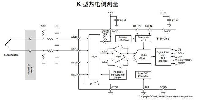
扫地机类清洁产品之直流无刷电机控制1.1前言扫地机产品有很多的电机控制,滚刷电机1个,边刷电机1-2个,清水泵电机,风机一个,部分中高端产品支持抹布功能,也就是存在抹布盘电机,还有追觅科沃斯石头等边刷抬升电机,滚刷抬升电机等的,这些电机有直流有刷电机,直接无刷电机,步进电机,电磁阀,挪动泵等不同类型。电机的原理,驱动控制方式也不行。接下来一段时间的几个文章会作个专题分析分享。直流有刷电机会自动持续
Linux下QT开发的动态库界面弹出操作(SDL2)
13jjyao
QT类qt开发语言sdl2linux
需求:操作系统为linux,开发框架为qt,做成需带界面的qt动态库,调用方为java等非qt程序难点:调用方为java等非qt程序,也就是说调用方肯定不带QApplication::exec(),缺少了这个,QTimer等事件和QT创建的窗口将不能弹出(包括opencv也是不能弹出);这与qt调用本身qt库是有本质的区别的思路:1.调用方缺QApplication::exec(),那么我们在接口
绘本讲师训练营【24期】8/21阅读原创《独生小孩》
1784e22615e0
24016-孟娟《独生小孩》图片发自App今天我想分享一个蛮特别的绘本,讲的是一个特殊的群体,我也是属于这个群体,80后的独生小孩。这是一本中国绘本,作者郭婧,也是一个80厚。全书一百多页,均为铅笔绘制,虽然为黑白色调,但并不显得沉闷。全书没有文字,犹如“默片”,但并不影响读者对该作品的理解,反而显得神秘,梦幻,給读者留下想象的空间。作者在前蝴蝶页这样写到:“我更希望父母和孩子一起分享这本书,使他
店群合一模式下的社区团购新发展——结合链动 2+1 模式、AI 智能名片与 S2B2C 商城小程序源码
说私域
人工智能小程序
摘要:本文探讨了店群合一的社区团购平台在当今商业环境中的重要性和优势。通过分析店群合一模式如何将互联网社群与线下终端紧密结合,阐述了链动2+1模式、AI智能名片和S2B2C商城小程序源码在这一模式中的应用价值。这些创新元素的结合为社区团购带来了新的机遇,提升了用户信任感、拓展了营销渠道,并实现了线上线下的完美融合。一、引言随着互联网技术的不断发展,社区团购作为一种新兴的商业模式,在满足消费者日常需
我校举行新老教师师徒结对仪式暨名师专业工作室工作交流活动
李蕾1229
为促进我校教师专业发展,发挥骨干教师的引领带头作用,11月6日下午,我校举行新老教师师徒结对仪式暨名师专业工作室工作交流活动。图片发自App会议由教师发展处李蕾主任主持,首先,由范校长宣读新老教师结对名单及双方承担职责。随后,两位新调入教师陈玉萍、莫正杰分别和他们的师傅鲍元美、刘召彬老师签订了师徒结对协议书。图片发自App图片发自App师徒拥抱、握手。有了师傅就有了目标有了方向,相信两位新教师在师
向内而求
陈陈_19b4
10月27日,阴。阅读书目:《次第花开》。作者:希阿荣博堪布,是当今藏传佛家宁玛派最伟大的上师法王,如意宝晋美彭措仁波切颇具影响力的弟子之一。多年以来,赴海内外各地弘扬佛法,以正式授课、现场开示、发表文章等多种方法指导佛学弟子修行佛法。代表作《寂静之道》、《生命这出戏》、《透过佛法看世界》自出版以来一直是佛教类书籍中的畅销书。图片发自App金句:1.佛陀说,一切痛苦的根源在于我们长期以来对自身及外
2021-08-26
影幽
在生活中,女人与男人的感悟往往有所不同。人生最大的舞台就是生活,大幕随时都可能拉开,关键是你愿不愿意表演都无法躲避。在生活中,遇事不要急躁,不要急于下结论,尤其生气时不要做决断,要学会换位思考,大事化小小事化了,把复杂的事情尽量简单处理,千万不要把简单的事情复杂化。永远不要扭曲,别人善意,无药可救。昨天是张过期的支票,明天是张信用卡,只有今天才是现金,要善加利用!执着的攀登者不必去与别人比较自己的
ArcGIS栅格计算器常见公式(赋值、0和空值的转换、补充栅格空值)
研学随笔
arcgis经验分享
我们在使用ArcGIS时通常经常用到栅格计算器,今天主要给大家介绍我日常中经常用到的几个公式,供大家参考学习。将特定值(-9999)赋值为0,例如-9999.Con("raster"==-9999,0,"raster")2.给空值赋予特定的值(如0)Con(IsNull("raster"),0,"raster")3.将特定的栅格值(如1)赋值为空值,其他保留原值SetNull("raster"==
高级编程--XML+socket练习题
masa010
java开发语言
1.北京华北2114.8万人上海华东2,500万人广州华南1292.68万人成都华西1417万人(1)使用dom4j将信息存入xml中(2)读取信息,并打印控制台(3)添加一个city节点与子节点(4)使用socketTCP协议编写服务端与客户端,客户端输入城市ID,服务器响应相应城市信息(5)使用socketTCP协议编写服务端与客户端,客户端要求用户输入city对象,服务端接收并使用dom4j
抖音乐买买怎么加入赚钱?赚钱方法是什么
测评君高省
你会在抖音买东西吗?如果会,那么一定要免费注册一个乐买买,抖音直播间,橱窗,小视频里的小黄车买东西都可以返佣金!省下来都是自己的,分享还可以赚钱乐买买是好省旗下的抖音返佣平台,乐买买分析社交电商的价值,乐买买属于今年难得的副业项目风口机会,2019年错过做好省的搞钱的黄金时期,那么2022年千万别再错过乐买买至于我为何转到高省呢?当然是高省APP佣金更高,模式更好,终端用户不流失。【高省】是一个自
那个抄袭的大张伟
猫小努
最近一直在追《即刻电音》这个综艺,除了觉得出场节目的音乐制作人有意思之外,也觉得有两个导师挺有趣的(另外一个就忽略了吧)。孙艺兴在上一篇文章里面已经说过了,那么这篇就说说我们的大老师,大张伟吧。其实在节目刚开始大张伟出来的时候,我以为他是属于导师里面来活跃气氛负责搞笑的,毕竟孙艺兴属于卖萌卖傻卖老实的,尚雯婕一般负责装逼耍狠的,而大张伟一贯以来上综艺的形象基本上都是蹦蹦跳跳带动气氛的。谁知道,两期
开心
蒋泳频
从无比抗拒来上课到接受,感动,收获~看着波哥成长,晶晶幸福笑容满面。感觉自己做的事情很有意义,很开心!还有3个感召目标就是还有三个有缘人,哈哈。明天感召去明日计划:8:30-11:00小公益11:00-21点上班,感召图片发自App图片发自App图片发自App
面向对象面向过程
3213213333332132
java
面向对象:把要完成的一件事,通过对象间的协作实现。
面向过程:把要完成的一件事,通过循序依次调用各个模块实现。
我把大象装进冰箱这件事为例,用面向对象和面向过程实现,都是用java代码完成。
1、面向对象
package bigDemo.ObjectOriented;
/**
* 大象类
*
* @Description
* @author FuJian
Java Hotspot: Remove the Permanent Generation
bookjovi
HotSpot
openjdk上关于hotspot将移除永久带的描述非常详细,http://openjdk.java.net/jeps/122
JEP 122: Remove the Permanent Generation
Author Jon Masamitsu
Organization Oracle
Created 2010/8/15
Updated 2011/
正则表达式向前查找向后查找,环绕或零宽断言
dcj3sjt126com
正则表达式
向前查找和向后查找
1. 向前查找:根据要匹配的字符序列后面存在一个特定的字符序列(肯定式向前查找)或不存在一个特定的序列(否定式向前查找)来决定是否匹配。.NET将向前查找称之为零宽度向前查找断言。
对于向前查找,出现在指定项之后的字符序列不会被正则表达式引擎返回。
2. 向后查找:一个要匹配的字符序列前面有或者没有指定的
BaseDao
171815164
seda
import java.sql.Connection;
import java.sql.DriverManager;
import java.sql.SQLException;
import java.sql.PreparedStatement;
import java.sql.ResultSet;
public class BaseDao {
public Conn
Ant标签详解--Java命令
g21121
Java命令
这一篇主要介绍与java相关标签的使用 终于开始重头戏了,Java部分是我们关注的重点也是项目中用处最多的部分。
1
[简单]代码片段_电梯数字排列
53873039oycg
代码
今天看电梯数字排列是9 18 26这样呈倒N排列的,写了个类似的打印例子,如下:
import java.util.Arrays;
public class 电梯数字排列_S3_Test {
public static void main(S
Hessian原理
云端月影
hessian原理
Hessian 原理分析
一. 远程通讯协议的基本原理
网络通信需要做的就是将流从一台计算机传输到另外一台计算机,基于传输协议和网络 IO 来实现,其中传输协议比较出名的有 http 、 tcp 、 udp 等等, http 、 tcp 、 udp 都是在基于 Socket 概念上为某类应用场景而扩展出的传输协
区分Activity的四种加载模式----以及Intent的setFlags
aijuans
android
在多Activity开发中,有可能是自己应用之间的Activity跳转,或者夹带其他应用的可复用Activity。可能会希望跳转到原来某个Activity实例,而不是产生大量重复的Activity。
这需要为Activity配置特定的加载模式,而不是使用默认的加载模式。 加载模式分类及在哪里配置
Activity有四种加载模式:
standard
singleTop
hibernate几个核心API及其查询分析
antonyup_2006
html.netHibernatexml配置管理
(一) org.hibernate.cfg.Configuration类
读取配置文件并创建唯一的SessionFactory对象.(一般,程序初始化hibernate时创建.)
Configuration co
PL/SQL的流程控制
百合不是茶
oraclePL/SQL编程循环控制
PL/SQL也是一门高级语言,所以流程控制是必须要有的,oracle数据库的pl/sql比sqlserver数据库要难,很多pl/sql中有的sqlserver里面没有
流程控制;
分支语句 if 条件 then 结果 else 结果 end if ;
条件语句 case when 条件 then 结果;
循环语句 loop
强大的Mockito测试框架
bijian1013
mockito单元测试
一.自动生成Mock类 在需要Mock的属性上标记@Mock注解,然后@RunWith中配置Mockito的TestRunner或者在setUp()方法中显示调用MockitoAnnotations.initMocks(this);生成Mock类即可。二.自动注入Mock类到被测试类 &nbs
精通Oracle10编程SQL(11)开发子程序
bijian1013
oracle数据库plsql
/*
*开发子程序
*/
--子程序目是指被命名的PL/SQL块,这种块可以带有参数,可以在不同应用程序中多次调用
--PL/SQL有两种类型的子程序:过程和函数
--开发过程
--建立过程:不带任何参数
CREATE OR REPLACE PROCEDURE out_time
IS
BEGIN
DBMS_OUTPUT.put_line(systimestamp);
E
【EhCache一】EhCache版Hello World
bit1129
Hello world
本篇是EhCache系列的第一篇,总体介绍使用EhCache缓存进行CRUD的API的基本使用,更细节的内容包括EhCache源代码和设计、实现原理在接下来的文章中进行介绍
环境准备
1.新建Maven项目
2.添加EhCache的Maven依赖
<dependency>
<groupId>ne
学习EJB3基础知识笔记
白糖_
beanHibernatejbosswebserviceejb
最近项目进入系统测试阶段,全赖袁大虾领导有力,保持一周零bug记录,这也让自己腾出不少时间补充知识。花了两天时间把“传智播客EJB3.0”看完了,EJB基本的知识也有些了解,在这记录下EJB的部分知识,以供自己以后复习使用。
EJB是sun的服务器端组件模型,最大的用处是部署分布式应用程序。EJB (Enterprise JavaBean)是J2EE的一部分,定义了一个用于开发基
angular.bootstrap
boyitech
AngularJSAngularJS APIangular中文api
angular.bootstrap
描述:
手动初始化angular。
这个函数会自动检测创建的module有没有被加载多次,如果有则会在浏览器的控制台打出警告日志,并且不会再次加载。这样可以避免在程序运行过程中许多奇怪的问题发生。
使用方法: angular .
java-谷歌面试题-给定一个固定长度的数组,将递增整数序列写入这个数组。当写到数组尾部时,返回数组开始重新写,并覆盖先前写过的数
bylijinnan
java
public class SearchInShiftedArray {
/**
* 题目:给定一个固定长度的数组,将递增整数序列写入这个数组。当写到数组尾部时,返回数组开始重新写,并覆盖先前写过的数。
* 请在这个特殊数组中找出给定的整数。
* 解答:
* 其实就是“旋转数组”。旋转数组的最小元素见http://bylijinnan.iteye.com/bl
天使还是魔鬼?都是我们制造
ducklsl
生活教育情感
----------------------------剧透请原谅,有兴趣的朋友可以自己看看电影,互相讨论哦!!!
从厦门回来的动车上,无意中瞟到了书中推荐的几部关于儿童的电影。当然,这几部电影可能会另大家失望,并不是类似小鬼当家的电影,而是关于“坏小孩”的电影!
自己挑了两部先看了看,但是发现看完之后,心里久久不能平
[机器智能与生物]研究生物智能的问题
comsci
生物
我想,人的神经网络和苍蝇的神经网络,并没有本质的区别...就是大规模拓扑系统和中小规模拓扑分析的区别....
但是,如果去研究活体人类的神经网络和脑系统,可能会受到一些法律和道德方面的限制,而且研究结果也不一定可靠,那么希望从事生物神经网络研究的朋友,不如把
获取Android Device的信息
dai_lm
android
String phoneInfo = "PRODUCT: " + android.os.Build.PRODUCT;
phoneInfo += ", CPU_ABI: " + android.os.Build.CPU_ABI;
phoneInfo += ", TAGS: " + android.os.Build.TAGS;
ph
最佳字符串匹配算法(Damerau-Levenshtein距离算法)的Java实现
datamachine
java算法字符串匹配
原文:http://www.javacodegeeks.com/2013/11/java-implementation-of-optimal-string-alignment.html------------------------------------------------------------------------------------------------------------
小学5年级英语单词背诵第一课
dcj3sjt126com
englishword
long 长的
show 给...看,出示
mouth 口,嘴
write 写
use 用,使用
take 拿,带来
hand 手
clever 聪明的
often 经常
wash 洗
slow 慢的
house 房子
water 水
clean 清洁的
supper 晚餐
out 在外
face 脸,
macvim的使用实战
dcj3sjt126com
macvim
macvim用的是mac里面的vim, 只不过是一个GUI的APP, 相当于一个壳
1. 下载macvim
https://code.google.com/p/macvim/
2. 了解macvim
:h vim的使用帮助信息
:h macvim
java二分法查找
蕃薯耀
java二分法查找二分法java二分法
java二分法查找
>>>>>>>>>>>>>>>>>>>>>>>>>>>>>>>>>>>>>>
蕃薯耀 2015年6月23日 11:40:03 星期二
http:/
Spring Cache注解+Memcached
hanqunfeng
springmemcached
Spring3.1 Cache注解
依赖jar包:
<!-- simple-spring-memcached -->
<dependency>
<groupId>com.google.code.simple-spring-memcached</groupId>
<artifactId>simple-s
apache commons io包快速入门
jackyrong
apache commons
原文参考
http://www.javacodegeeks.com/2014/10/apache-commons-io-tutorial.html
Apache Commons IO 包绝对是好东西,地址在http://commons.apache.org/proper/commons-io/,下面用例子分别介绍:
1) 工具类
2
如何学习编程
lampcy
java编程C++c
首先,我想说一下学习思想.学编程其实跟网络游戏有着类似的效果.开始的时候,你会对那些代码,函数等产生很大的兴趣,尤其是刚接触编程的人,刚学习第一种语言的人.可是,当你一步步深入的时候,你会发现你没有了以前那种斗志.就好象你在玩韩国泡菜网游似的,玩到一定程度,每天就是练级练级,完全是一个想冲到高级别的意志力在支持着你.而学编程就更难了,学了两个月后,总是觉得你好象全都学会了,却又什么都做不了,又没有
架构师之spring-----spring3.0新特性的bean加载控制@DependsOn和@Lazy
nannan408
Spring3
1.前言。
如题。
2.描述。
@DependsOn用于强制初始化其他Bean。可以修饰Bean类或方法,使用该Annotation时可以指定一个字符串数组作为参数,每个数组元素对应于一个强制初始化的Bean。
@DependsOn({"steelAxe","abc"})
@Comp
Spring4+quartz2的配置和代码方式调度
Everyday都不同
代码配置spring4quartz2.x定时任务
前言:这些天简直被quartz虐哭。。因为quartz 2.x版本相比quartz1.x版本的API改动太多,所以,只好自己去查阅底层API……
quartz定时任务必须搞清楚几个概念:
JobDetail——处理类
Trigger——触发器,指定触发时间,必须要有JobDetail属性,即触发对象
Scheduler——调度器,组织处理类和触发器,配置方式一般只需指定触发
Hibernate入门
tntxia
Hibernate
前言
使用面向对象的语言和关系型的数据库,开发起来很繁琐,费时。由于现在流行的数据库都不面向对象。Hibernate 是一个Java的ORM(Object/Relational Mapping)解决方案。
Hibernte不仅关心把Java对象对应到数据库的表中,而且提供了请求和检索的方法。简化了手工进行JDBC操作的流程。
如
Math类
xiaoxing598
Math
一、Java中的数字(Math)类是final类,不可继承。
1、常数 PI:double圆周率 E:double自然对数
2、截取(注意方法的返回类型) double ceil(double d) 返回不小于d的最小整数 double floor(double d) 返回不大于d的整最大数 int round(float f) 返回四舍五入后的整数 long round


