STM32F429 >> 13. SPI 通讯
本工程板级支持包文件适用于野火stm32f429 开发板。
SPI 物理层
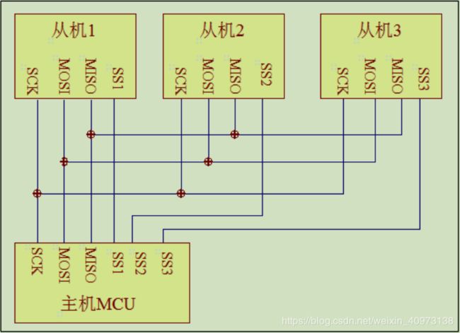 SPI 通讯使用3 条总线及片选线,3 条总线分别是SCK、MOSI、MISO,片选线为SS,其作用分别为:
- SS:片选信号线,也称NSS、CS。当有多个SPI 从设备与SPI 主机相连时,设备的其他信号线 SCK、MOSI及 MISO同时并联到相同的 SPI总线上,即无论有多少个从设备,都共同只使用这 3 条总线;而每个从设备都有独立的这一条 NSS 信号线,本信号线独占主机的一个引脚,即有多少个从设备,就有多少条片选信号线。
I2C 协议中通过设备地址来寻址、选中总线上的某个设备并与其进行通讯;而 SPI 协议中没有设备地址,它使用 NSS 信号线来寻址,当主机要选择从设备时,把该从设备的 NSS 信号线设置为低电平,该从设备即被选中,即片选有效,接着主机开始与被选中的从设备进行 SPI 通讯。所以SPI通讯以 NSS 线置低电平为开始信号,以 NSS 线被拉高作为结束信号。 - SCK:时钟信号线,用于通讯数据同步。它由通讯主机产生,决定了通讯的速率,不同的设备支持的最高时钟频率不一样,如 STM32 的 SPI 时钟频率最大为f pclk /2,两个设备之间通讯时,通讯速率受限于低速设备。
- MOSI:主设备输出/从设备输入引脚。主机的数据从这条信号线输出,从机由这条信号线读入主机发送的数据,即这条线上数据的方向为主机到从机。
- MISO:主设备输入/从设备输出引脚。主机从这条信号线读入数据,从机的数据由这条信号线输出到主机,即在这条线上数据的方向为从机到主机。
协议层
SPI 基本通讯过程
- SPI 的起始信号:NSS 信号线由高变低。
- SPI 使用MOSI 及MISO 信号线传输数据,使用SCK 信号线进行数据同步。MOSI
及 MISO数据线在 SCK的每个时钟周期传输一位数据,且数据输入输出是同时进行的。数据传输时,MSB先行或 LSB先行并没有作硬性规定,但要保证两个 SPI通讯设备之间使用同样的协定。
MOSI及 MISO的数据在 SCK的上升沿期间变化输出,在 SCK的下降沿时被采样。即在 SCK的下降沿时刻,MOSI及 MISO的数据有效。
SPI每次数据传输可以 8 位或 16 位为单位,每次传输的单位数不受限制。 - SPI 的停止信号:NSS 信号线由低变高。
CPOL/CPHA 及通讯模式
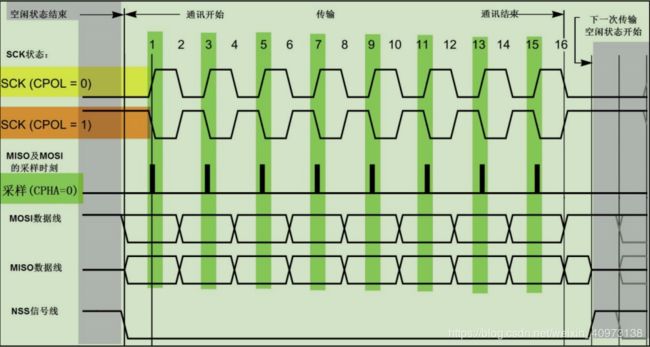
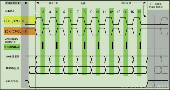
上面讲述的时序只是 SPI中的其中一种通讯模式,SPI一共有四种通讯模式,它们的主要区别是总线空闲时 SCK的时钟状态以及数据采样时刻。
为方便说明,在此引入“时钟极性 CPOL”和“时钟相位 CPHA”的概念。
时钟极性 CPOL是指 SPI通讯设备处于空闲状态时,SCK信号线的电平信号(即 SPI通讯开始前、 NSS 线为高电平时 SCK的状态)。CPOL=0时, SCK在空闲状态时为低电平,CPOL=1 时,则相反。
时钟相位 CPHA是指数据的采样的时刻,当 CPHA=0 时,MOSI或 MISO 数据线上的信号将会在 SCK时钟线的“奇数边沿”被采样。当 CPHA=1 时,数据线在 SCK的“偶数边沿”采样。

简单来说就是:
CPOL(0/1)控制时钟信号是正向脉冲还是反向脉冲;CPHA(0/1)控制采样信号是时钟脉冲起始还是时钟脉冲结束。
架构
- 通讯引脚

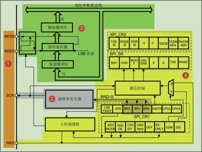
其中 SPI1、SPI4、SPI5、SPI6是 APB2 上的设备,最高通信速率达 45Mbtis/s,SPI2、SPI3 是 APB1上的设备,最高通信速率为 22.5Mbits/s。其它功能上没有差异。 - 时钟控制逻辑
SCK线的时钟信号,由波特率发生器根据“控制寄存器 CR1”中的 BR[0:2]位控制,该位是对 f pclk 时钟的分频因子,对 f pclk 的分频结果就是 SCK引脚的输出时钟频率。

其中的 f pclk 频率是指 SPI所在的 APB总线频率,APB1为 f pclk1 ,APB2为 f pckl2 。
通过配置“控制寄存器 CR”的“CPOL位”及“CPHA”位可以把 SPI设置成前面分析的 4 种 SPI模式。
3. 数据控制逻辑
SPI的 MOSI及 MISO 都连接到数据移位寄存器上,数据移位寄存器的内容来源于接收缓冲区及发送缓冲区以及 MISO、MOSI线。
当向外发送数据的时候,数据移位寄存器以“发送缓冲区”为数据源,把数据一位一位地通过数据线发送出去;当从外部接收数据的时候,数据移位寄存器把数据线采样到的数据一位一位地存储到“接收缓冲区”中。
通过写 SPI的“数据寄存器 DR”把数据填充到发送缓冲区中,通过 “数据寄存器 DR”,可以获取接收缓冲区中的内容。
其中数据帧长度可以通过“控制寄存器 CR1”的“DFF位”配置成 8 位及 16 位模式;置“LSBFIRST 位”可选择 MSB先行还是 LSB先行。
4. 整体控制逻辑
整体控制逻辑负责协调整个 SPI外设,控制逻辑的工作模式根据我们配置的“控制寄存器(CR1/CR2)”的参数而改变,基本的控制参数包括前面提到的 SPI模式、波特率、LSB先行、主从模式、单双向模式等等。在外设工作时,控制逻辑会根据外设的工作状态修改“状态寄存器(SR)”,我们只要读取状态寄存器相关的寄存器位,就可以了解 SPI的工作状态了。除此之外,控制逻辑还根据要求,负责控制产生 SPI中断信号、DMA 请求及控制NSS 信号线。
实际应用中,我们一般不使用 STM32 SPI外设的标准 NSS 信号线,而是更简单地使用
普通的 GPIO,软件控制它的电平输出,从而产生通讯起始和停止信号。
通讯过程
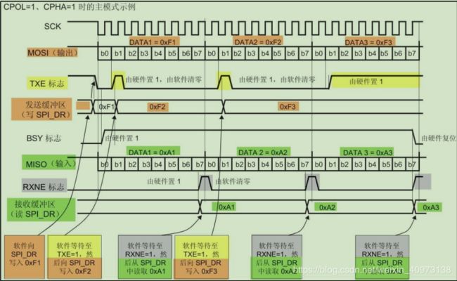
此为STM32 作为SPI 通讯的主机端时的数据收发过程 ↑
主模式收发流程及事件说明:
- 控制NSS 信号线,产生起始信号(图中没有画出);
- 把要发送的数据写入到“数据寄存器 DR”中,该数据会被存储到发送缓冲区;
- 通讯开始,SCK时钟开始运行。MOSI把发送缓冲区中的数据一位一位地传输出去;MISO 则把数据一位一位地存储进接收缓冲区中(全双工);
- 当发送完一帧数据的时候,“状态寄存器 SR”中的“TXE 标志位”会被置 1,表示传输完一帧,发送缓冲区已空;类似地,当接收完一帧数据的时候,“RXNE标志位”会被置 1,表示传输完一帧,接收缓冲区非空;
- 等待到“TXE标志位”为 1 时,若还要继续发送数据,则再次往“数据寄存器DR”写入数据即可;等待到“RXNE标志位”为 1时,通过读取“数据寄存器DR”可以获取接收缓冲区中的内容。
SPI 读写串行FLASH
FLASH(闪存)与EEPROM 都是掉电后数据不丢失的存储器,但FLASH 的容量普遍大于EEPROM;
存储控制上,最主要的区别是FLASH 芯片只能一大片一大片地擦写,而EEPROM 可以单个字节擦写。
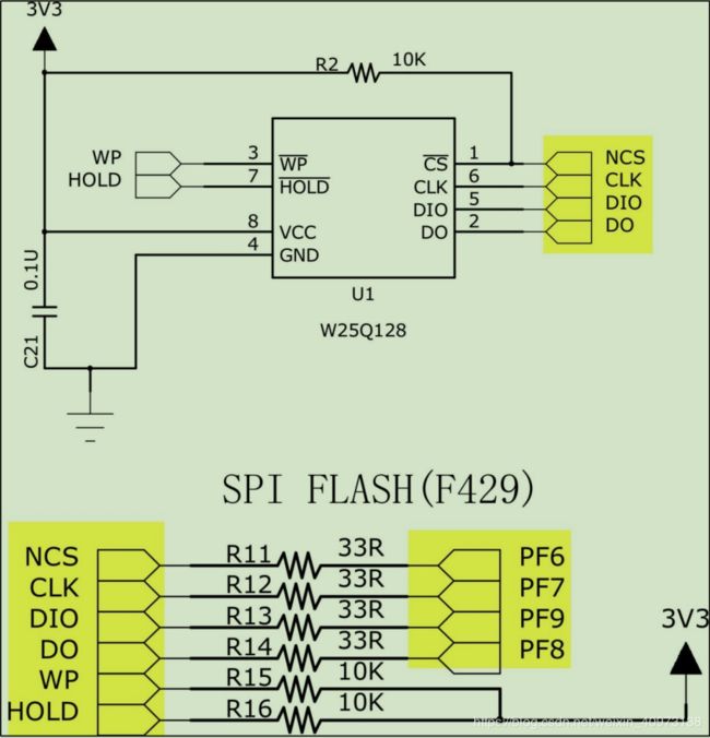
STM32 的NSS 引脚是一个普通的GPIO,不是SPI 的专用NSS 引脚,需要用软件控制
控制FLASH 的指令
在与EEPROM 进行I²C 通讯时,第一个和第二个字节的数据分别会被视作硬件地址和内部存储矩阵地址。
但在与FLASH 进行SPI 通讯 时,FLASH 芯片自定义了很多指令,对于STM32 主机来说,这些字节就是普通的数据,而对于FLASH 来说,不同的数据将会被翻译成不同的指令。
其常用芯片指令有:

该表中的第一列为指令名,第二列为指令编码,第三至第 N 列的具体内容根据指令的不同而有不同的含义。
其中带括号的字节参数,方向为 FLASH 向主机传输,即命令响应,不带括号的则为主机向 FLASH 传输。
表中“A0~A23”指 FLASH 芯片内部存储器组织的地址;“M0~M7”为厂商号(MANUFACTURER ID);“ID0-ID15”为 FLASH 芯片的ID;“dummy”指该处可为任意数据;“D0~D7”为 FLASH 内部存储矩阵的内容。
编程要点:
- 初始化通讯使用的目标引脚及端口时钟;
- 使能SPI 外设的时钟;
- 配置SPI 外设的模式、地址、速率等参数并使能SPI 外设;
- 编写基本SPI 按字节收发的函数;
- 编写对FLASH 擦除及读写操作的函数;
- 编写测试程序,对读写数据进行校验。
以下是各个模块的分代码
==============总代码在这
bsp_spi_flash.h
/**
******************************************************************************
* @file bsp_spi_flash.h
* @author Waao
* @version V1.0.0
* @date 19-Jan-2019
* @brief This file contains some board support package's definitions for the SPI.
*
******************************************************************************
* @attention
*
* None
*
******************************************************************************
*/
#ifndef _BSP_SPI_FLASH_H_
#define _BSP_SPI_FLASH_H_
#include bsp_spi_flash.c
/**
******************************************************************************
* @file bsp_spi_flash.c
* @author Waao
* @version V1.0.0
* @date 19-Jan-2019
* @brief This file contains some board support package's functions for the SPI.
*
******************************************************************************
* @attention
*
* None
*
******************************************************************************
*/
#include 读ID 指令"JEDEX ID"
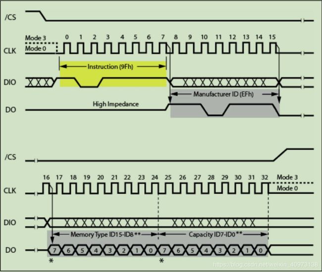
主机首先通过 MOSI线向 FLASH 芯片发送第一个字节数据为“9F h”,当 FLASH 芯片收到该数据后,它会解读成主机向它发送了“JEDEC 指令”,然后它就作出该命令的响应:通过 MISO 线把它的厂商 ID(M7-M0)及芯片类型(ID15-0)发送给主机,主机接收到指令响应后可进行校验。常见的应用是主机端通过读取设备 ID 来测试硬件是否连接正常,或用于识别设备。
/**
  * @brief  Read the flash's ID
	* @param  None
	* @retval temp: The ID of the FLASH
  */
u32 SPI_FLASH_ReadID(void)
{
	u32 temp = 0, temp_1 = 0, temp_2 = 0, temp_3 = 0;

	SPI_FLASH_CS_0;

	SPI_FLASH_SendByte(W25X_JedecDeviceID);

	temp_1 = SPI_FLASH_ReadByte();
	temp_2 = SPI_FLASH_ReadByte();
	temp_3 = SPI_FLASH_ReadByte();

	SPI_FLASH_CS_1;

	temp = (temp_1 << 16) | (temp_2 << 8) | temp_3;

	return temp;
}
写使能以及读取当前状态
/**
  * @brief  Write enable
	* @param  None
	* @retval None
  */
void SPI_FLASH_WriteEnable(void)
{
	SPI_FLASH_CS_0;

	SPI_FLASH_SendByte(W25X_WriteEnable);

	SPI_FLASH_CS_1;
}


/**
  * @brief  Wait for the FLASH idle
	* @param  None
	* @retval 0: Succeed
	*					1: False
  */
u8 SPI_FLASH_WaitForWriteEnd(void)
{
	u8 FLASH_Status = 0;

	SPI_FLASH_CS_0;

	SPI_FLASH_SendByte(W25X_ReadStatusReg);

	// There is better to be SPIT_LONG_TIMEOUT rather than SPIT_FLAG_TIMEOUT, or it will make a mistake
	SPITimeout = SPIT_LONG_TIMEOUT;

	do
	{
		FLASH_Status = SPI_FLASH_SendByte(Dummy_Byte);//SPI_FLASH_ReadByte();

		if((SPITimeout--) == 0)
		{
			SPI_TIMEOUT_Callback(2);
			return 1;
		}
	}
	while((FLASH_Status & WIP_Flag) == SET);

	SPI_FLASH_CS_1;
	return 0;
}
FLASH 扇区擦除
FLASH 的特性决定其只能将原来为“1” 的数据位改为“0”,而原来为“0” 的数据位却不能直接改写为“1”。
所以这里涉及到数据“擦除” 的概念,在写入前,必须要对目标存储矩阵进行擦除操作,将矩阵中的数据位擦除为“1”,在数据写入的时候,如果要存储数据“1”,那就不修改存储矩阵,在要存储数据“0” 时,才要更改该位。
通常,对存储矩阵擦除的基本操作单位都是多个字节进行,如本例子中的 FLASH 芯片支持“扇区擦除”、“块擦除”以及“整片擦除”

FLASH 芯片的最小擦除单位为扇区(Sector),而一个块(Block)包含16个扇区
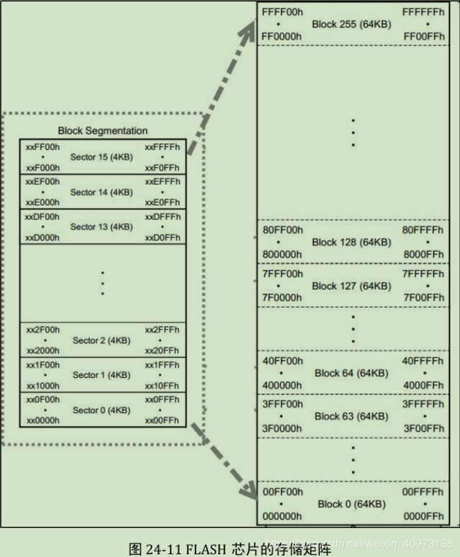
使用“Sector Erase” 指令可控制FLASH 芯片进行擦写操作,第一个字节为指令编码,紧接着发送的3个字节用于表示要擦除的存储矩阵地址。
需要注意的是:在扇区擦除指令前,需要先发送“写使能” 指令,发送扇区擦除指令后,通过读取寄存器状态等待扇区擦除操作完毕。
注意地址要对齐4KB
/**
    * @brief  Erase the sector that you specified
	* @param  SectorAddr: The address of the buffer that you want to erase
	* @retval None
  */
void SPI_FLASH_SectorErase(u32 SectorAddr)
{
	SPI_FLASH_CS_0;

	SPI_FLASH_WriteEnable();

	SPI_FLASH_SendByte(W25X_SectorErase);
	SPI_FLASH_SendByte((SectorAddr & 0xFF0000) >> 16);
	SPI_FLASH_SendByte((SectorAddr & 0xFF00) >> 18);
	SPI_FLASH_SendByte(SectorAddr & 0xFF);

	SPI_FLASH_CS_1;

  SPI_FLASH_WaitForWriteEnd();
}
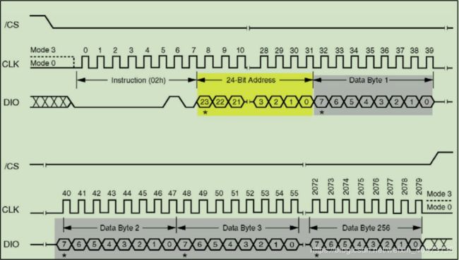
FLASH 的页写入
使用页写入命令最多可以一次向 FLASH 传输 256 个字节的数据,我们把这个单位为页大小。
/**
  * @brief  Write a page of data
	* @param  pBuffer: The pointer point to our data
	*					WriteAddr: The place that we want to restore the data
	*					NumByteToWrite: The number of bytes that we want to write
	* @retval None
  */
void SPI_FLASH_PageWrite(u8 *pBuffer, u32 WriteAddr, u16 NumByteToWrite)
{
	SPI_FLASH_CS_0;

	SPI_FLASH_WriteEnable();

	SPI_FLASH_SendByte(W25X_PageProgram);
	SPI_FLASH_SendByte((WriteAddr & 0xFF0000) >> 16);
	SPI_FLASH_SendByte((WriteAddr & 0xFF00) >> 18);
	SPI_FLASH_SendByte(WriteAddr & 0xFF);

	if(NumByteToWrite > SPI_FLASH_PerWritePageSize)
	{
		NumByteToWrite = SPI_FLASH_PerWritePageSize;
		FLASH_ERROR("SPI_FLASH_PageWrite too large!");
	}

	while(NumByteToWrite--)
	{
		SPI_FLASH_SendByte(*pBuffer);
		pBuffer++;
	}

	SPI_FLASH_CS_1;

  SPI_FLASH_WaitForWriteEnd();
}
不定量数据写入
不定量数据写入不受页写入的字节控制,更为方便
/**
  * @brief  Write a buffer of data
	* @param  pBuffer: The pointer point to our data
	*					WriteAddr: The place that we want to restore the data
	*					NumByteToWrite: The number of bytes that we want to write
	* @retval None
  */
void SPI_FLASH_BufferWrite(u8 *pBuffer, u32 WriteAddr, u16 NumByteToWrite)
{
	//The Addr_Surplus_page is the difference value that WriteAddr reach a page
	u32 Addr_Surplus_page = WriteAddr - (WriteAddr % SPI_FLASH_PageSize);
	//The Byte_Numpage is the integer of WriteAddr devided by SPI_FLASH_PageSize
	u32 Byte_Numpage = (NumByteToWrite - Addr_Surplus_page) / SPI_FLASH_PageSize;
	//The Byte_Remainder is the remainder of WriteAddr devided by SPI_FLASH_PageSize
	u32 Byte_Remainder = (NumByteToWrite - Addr_Surplus_page) % SPI_FLASH_PageSize;

	u32 i = 0;

	SPI_FLASH_SendByte(W25X_PageProgram);
	SPI_FLASH_SendByte((WriteAddr & 0xFF0000) >> 16);
	SPI_FLASH_SendByte((WriteAddr & 0xFF00) >> 18);
	SPI_FLASH_SendByte(WriteAddr & 0xFF);

	/* First we consider the situation of the Addr_Surplus_page is not equal with WriteAddr, the mean is that
	 * the WriteAddr isn't reach the integer times of SPI_FLASH_PageSize.
	 */
	if(Addr_Surplus_page != WriteAddr)
	{
		// We should fill the first page
		SPI_FLASH_PageWrite(pBuffer, WriteAddr, Addr_Surplus_page);
		pBuffer += Addr_Surplus_page;
		WriteAddr += Addr_Surplus_page;
		// Then we consider the situation of the number of bytes of data is more than one page after it fill the first page.
		if(Byte_Numpage > 0)
		{
			while(Byte_Numpage--)
			{
				SPI_FLASH_PageWrite(pBuffer, WriteAddr, SPI_FLASH_PageSize);
				pBuffer += SPI_FLASH_PageSize;
				WriteAddr += SPI_FLASH_PageSize;
			}
			// And we consider the situation of the data can't reach a new page after it fill the ahead page.
			if(Byte_Remainder > 0)
			{
				while(Byte_Remainder--)
				{
					SPI_FLASH_PageWrite(pBuffer, WriteAddr, Byte_Remainder);
					pBuffer += Byte_Remainder;
					WriteAddr += Byte_Remainder;
				}
			}
		}
		// Or the situation is the data can't reach a new page after it fill the first page.
		if(Byte_Numpage == 0 && Byte_Remainder > 0)
		{
			for(i=0; i<Byte_Remainder; i++)
			{
				SPI_FLASH_PageWrite(pBuffer, WriteAddr, Byte_Remainder);
				pBuffer += Byte_Remainder;
				WriteAddr += Byte_Remainder;
			}
		}

	}
	/* Another situation is the WriteAddr is just the integer times of the SPI_FLASH_PageSize, the mean is
	 * that we can write the data from a new page directly.
	 */
	if(Addr_Surplus_page == WriteAddr)
	{
		if(Byte_Numpage > 0)
		{
			while(Byte_Numpage--)
			{
				SPI_FLASH_PageWrite(pBuffer, WriteAddr, SPI_FLASH_PageSize);
				pBuffer += SPI_FLASH_PageSize;
				WriteAddr += SPI_FLASH_PageSize;
			}
			if(Byte_Remainder > 0)
			{
				SPI_FLASH_PageWrite(pBuffer, WriteAddr, Byte_Remainder);
				pBuffer += Byte_Remainder;
				WriteAddr += Byte_Remainder;
			}
		}
		if(Byte_Numpage == 0 && Byte_Remainder > 0)
		{
			SPI_FLASH_PageWrite(pBuffer, WriteAddr, Byte_Remainder);
			pBuffer += Byte_Remainder;
			WriteAddr += Byte_Remainder;
		}
	}
}
从FLASH 读取数据
发送了“Read Data” 的指令编码及要读的起始地址后,FLASH 芯片就会按地址递增的方式返回存储矩阵的内容,读取的数据量没有限制,只要没有停止通讯,FLASH 芯片就会一直返回数据

/**
  * @brief  Read a buffer of data
	* @param  pBuffer: The pointer point to the data
	*					WriteAddr: The place that we want to find the data
	*					NumByteToWrite: The number of bytes that we want to read
	* @retval None
  */
void SPI_FLASH_BufferRead(u8 *pBuffer, u32 ReadAddr, u16 NumByteToWrite)
{
	u32 i;

	SPI_FLASH_CS_0;

	SPI_FLASH_SendByte(W25X_ReadData);
	SPI_FLASH_SendByte((ReadAddr & 0xFF0000) >> 16);
	SPI_FLASH_SendByte((ReadAddr & 0xFF00) >> 18);
	SPI_FLASH_SendByte(ReadAddr & 0xFF);

	for(i=0; i<NumByteToWrite; i++)
	{
		pBuffer[i] = SPI_FLASH_SendByte(Dummy_Byte);
	}

	SPI_FLASH_CS_1;
}

