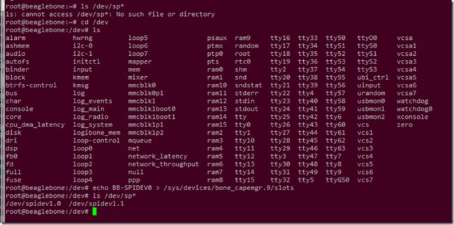
这次用 SPI。BBB 有两套 SPI 接口可用,两套都是默认 disable,需要用 overlay 方式启用,即:
echo BB-SPIDEV0 > /sys/devices/bone_capemgr.9/slots
我的 BBB 当前配置当前配置
/opt/source/Userspace-Arduino/overlay/BB-SPI0-01-00A0.dts
/dts-v1/;
/plugin/;
/ {
compatible = "ti,beaglebone", "ti,beaglebone-black";
/* identification */
part-number = "spi0pinmux";
fragment@0 {
target = <&am33xx_pinmux>;
__overlay__ {
spi0_pins_s0: spi0_pins_s0 {
pinctrl-single,pins = <
0x150 0x30 /* spi0_sclk, INPUT_PULLUP | MODE0 */
0x154 0x30 /* spi0_d0, INPUT_PULLUP | MODE0 */
0x158 0x10 /* spi0_d1, OUTPUT_PULLUP | MODE0 */
0x15c 0x10 /* spi0_cs0, OUTPUT_PULLUP | MODE0 */
>;
};
};
};
fragment@2 {
target = <&spi0>;
__overlay__ {
#address-cells = <1>;
#size-cells = <0>;
status = "okay";
pinctrl-names = "default";
pinctrl-0 = <&spi0_pins_s0>;
spidev@0 {
spi-max-frequency = <24000000>;
reg = <0>;
compatible = "linux,spidev";
};
};
};
};
说明书第三十页,BMP280 支持 Mode 00 和 11,自动选的。可三线或四线连接。
dts 档内可见,当前就是 mode 0,可以直接连 BMP280了。
SPI 接线 – BMP280
原理图在上一篇博文,从图可以得知,BMP280 的片选是 CSB,NCS 是九轴 MPU9250 的片选引脚。
我那很烂的焊接,锡明显过多,烙铁温度过高,家里没洗板水,脏兮兮的。SPI0 的接线如下:
| BBB | GY-91 | 说明 |
| P9_1 | GND | 地 |
| P9_3 | 3V3 | 电源 |
| P9_22 | SCL | 时钟 |
| P9_17 | CSB | 片选 |
| P9_18 | SDA | MOSI |
| P9_21 | SA0 | MISO |
启用 SPI0 :
echo BB-SPIDEV0 > /sys/devices/bone_capemgr.9/slots
然后在 /dev 就会出现了:
spidev1.0 代表总线号 1 片选号 0。
SPI 读取 BMP280 的 ID Register 值
注意事项如上图,图片截取自 BMP280 Datasheet,BMP280 的 SPI Read 方式从 BBB 发出的一个 byte 是 Control byte,Control byte 的 bit 7 用来控制读写,地址是后面余下的 7 个 bits。上图Control byte 后面的 Data byte 是接收的,比如我四线情况,它在 MISO 出现的,上图这样表达比较难理解……。
看一下时序图,看这个我比较好理解一些:
通讯过程中片选 pull down。
毕竟主角是九轴,BMP280温度气压就快速试一次,试试而已。C 代码。
有好几段小插曲,我首先想用 Python,易写易改,找到了SPIDEV,可是无论如何都无法用双工连,最终由于时间关系,放弃了。PY-SPIDEV见以此链接:
https://pypi.python.org/pypi/spidev 。后来改用 C,各种百度FQ再 Google,多半是 Arduino 和用上 Adafruit 的类库,看到各种 Digital Write,最后也放弃了。最后直接用 linux/spi/spidev 自己参考一下别人就直接写。
#include#include #include #include #include #include #include char buf[1]; char buf2[10]; struct spi_ioc_transfer xfer[2]; int spi_init(char filename[40]) { int file; __u8 mode = 0; __u8 lsb = 0; __u8 bits = 8; __u32 speed = 10000000; if ((file = open(filename,O_RDWR)) < 0) { printf("Failed to open the bus."); exit(1); } if (ioctl(file, SPI_IOC_WR_MODE, &mode)<0) { perror("can't set spi mode"); return; } if (ioctl(file, SPI_IOC_RD_MODE, &mode) < 0) { perror("SPI rd_mode"); return; } if (ioctl(file, SPI_IOC_RD_LSB_FIRST, &lsb) < 0) { perror("SPI rd_lsb_fist"); return; } if (ioctl(file, SPI_IOC_WR_BITS_PER_WORD, &bits)<0) { perror("can't set bits per word"); return; } if (ioctl(file, SPI_IOC_RD_BITS_PER_WORD, &bits) < 0) { perror("SPI bits_per_word"); return; } if (ioctl(file, SPI_IOC_WR_MAX_SPEED_HZ, &speed)<0) { perror("can't set max speed hz"); return; } if (ioctl(file, SPI_IOC_RD_MAX_SPEED_HZ, &speed) < 0) { perror("SPI max_speed_hz"); return; } printf("%s: spi mode %d, %d bits %sper word, %d Hz max\n",filename, mode, bits, lsb ? "(lsb first) " : "", speed); return file; } char * spi_read(int addr,int nbytes,int file) { int status; memset(buf, 0, sizeof buf); memset(buf2, 0, sizeof buf2); buf[0] = addr | 128; xfer[0].tx_buf = (unsigned long)buf; xfer[0].len = 1; xfer[1].rx_buf = (unsigned long) buf2; xfer[1].len = nbytes; status = ioctl(file, SPI_IOC_MESSAGE(2), xfer); if (status < 0) { perror("SPI_IOC_MESSAGE"); return; } return buf2; } int main(){ char * buffer; int file=spi_init("/dev/spidev1.0"); buffer = spi_read(0xD0,1,file); printf("0x%x\n",*buffer); }
代码改自这里:http://linux-sunxi.org/SPIdev,原版是 SUNXI 的,我已修改并去掉些不合理地方。
首先配置, 默认 mode 0 ,8 bit per word 再把速度调到BMP280 的上限 10MHz,然后用 read 方法,两个 xfer 丢进去,一个是写 0xD0,代表我想读取 ID Register,一个是读取的 buf2,返回 buf2 到 main 再打印出来。read 里面的 bitwise OR 是为了确保 bit 7 是 1,以免我敲错地址错误地操作了写入。效果:
返回 0x58,ID 正确。
SPI 写入 BMP280 Register,读取当前温度
对 BMP280 的 ctrl_meas 写入值,连续测量,最高精度,只检测温度不管气压(地址和值见上一篇),然后读取气温原始数据和温度补偿,再转换为摄氏 printf 出来,代码:
#include#include #include #include #include #include #include #include #define DIG_START 0x88 #define TEMP_START 0xFA #define CTRL_MEAS 0xF4 #define TEMP_ONLY_NORMAL_MODE 0xE3 // 111 000 11 char buf[10]; char buf2[10]; struct spi_ioc_transfer xfer[2]; int spi_init(char filename[40]) { int file; __u8 lsb = 0; __u8 mode = 0; __u8 bits = 8; __u32 speed = 10000000; if ((file = open(filename,O_RDWR)) < 0) { printf("Failed to open the bus."); exit(1); } if (ioctl(file, SPI_IOC_WR_MODE, &mode)<0) { perror("can't set spi mode"); return; } if (ioctl(file, SPI_IOC_RD_MODE, &mode) < 0) { perror("SPI rd_mode"); return; } if (ioctl(file, SPI_IOC_RD_LSB_FIRST, &lsb) < 0) { perror("SPI rd_lsb_fist"); return; } if (ioctl(file, SPI_IOC_WR_BITS_PER_WORD, &bits)<0) { perror("can't set bits per word"); return; } if (ioctl(file, SPI_IOC_RD_BITS_PER_WORD, &bits) < 0) { perror("SPI bits_per_word"); return; } if (ioctl(file, SPI_IOC_WR_MAX_SPEED_HZ, &speed)<0) { perror("can't set max speed hz"); return; } if (ioctl(file, SPI_IOC_RD_MAX_SPEED_HZ, &speed) < 0) { perror("SPI max_speed_hz"); return; } return file; } char * spi_read(int addr,int nbytes,int file) { int status; memset(buf, 0, sizeof buf); memset(buf2, 0, sizeof buf2); buf[0] = addr | 128; xfer[0].tx_buf = (unsigned long)buf; xfer[0].len = 1; xfer[1].rx_buf = (unsigned long) buf2; xfer[1].len = nbytes; status = ioctl(file, SPI_IOC_MESSAGE(2), xfer); if (status < 0) { perror("SPI_IOC_MESSAGE"); return; } return buf2; } void spi_write(int addr, char value, int file) { int status; memset(buf, 0, sizeof buf); buf[0] = addr & 127; buf[1] = value; xfer[0].tx_buf = (unsigned long)buf; xfer[0].len = 2; status = ioctl(file, SPI_IOC_MESSAGE(1), xfer); if (status < 0) { perror("SPI_IOC_MESSAGE"); } } float myFunc(uint32_t adc_T, unsigned short dig_T1, short dig_T2, short dig_T3){ uint32_t var1, var2; float T; var1 = (((double)adc_T)/16384.0-((double)dig_T1)/1024.0)*((double)dig_T2); var2 = ((((double)adc_T)/131072.0-((double)dig_T1)/8192.0)*(((double)adc_T)/131072.0-((double)dig_T1)/8192.0))*((double)dig_T2); T = (var1+var2)/5120.0; return T; } int main() { int i; char * id; char * mode; char dig_buff[6]; char tmp_buff[3]; int file=spi_init("/dev/spidev1.0"); id = spi_read(0xD0,1,file); printf("ID: 0x%02x\n",*id); spi_write(CTRL_MEAS,TEMP_ONLY_NORMAL_MODE,file); mode = spi_read(CTRL_MEAS,1,file); printf("Mode: 0x%02x\n", *mode); memcpy(dig_buff, spi_read(DIG_START, 6, file), 6); memcpy(tmp_buff, spi_read(TEMP_START, 3, file), 3); printf("Dump:\n"); for (i=0; i<6; i++){ printf("%02x ",dig_buff[i]); } printf("\n"); for (i=0; i<3; i++){ printf("%02x ",tmp_buff[i]); } printf("\n"); int adc_T = ((tmp_buff[0]<<16)|(tmp_buff[1]<<8)|(tmp_buff[2]))>>4; unsigned short dig_T1 = (dig_buff[1]<<8)|(dig_buff[0]); short dig_T2 = (dig_buff[3]<<8)|(dig_buff[2]); short dig_T3 = (dig_buff[5]<<8)|(dig_buff[4]); printf("adc_T is : %d \n", adc_T); printf("dig_T1 is : %d \n", dig_T1); printf("dig_T2 is : %d \n", dig_T2); printf("dig_T3 is : %d \n", dig_T3); printf("Temperature is : %f \n", myFunc(adc_T, dig_T1, dig_T2, dig_T3)); return 0; }
效果:
关于温度补偿和实际摄氏温度计算,请看上一篇 I2C 示范。spi_write 里面的 bitwise AND 是为了确保 bit 7 是零,写入模式。由于我全部用相同的 buf 和 buf2,实际应用 read 时候需要 copy 出来。我还没很好地理解 linux 的 spidev 库(比如读取时两个 xfer buffer 是否需要大小一致,片选结束拉低的时间点是取决于 xfer[0] 长度还是 xfer[0] 和 xfer[1] 两者较长的值,初始化后 SPI 参数能否修改,user space 能否改 mode 等等的问题),但以上代码勉强够用了,将来有空再慢慢研究。将来的项目里不是 embedded linux 的。
我纠结于尝试用 Python 做 SPI 双工浪费了很多时间,最终还是没结果做不出来。最后放弃那一层层的封装,直接用 C 的 spidev,顿时春天了,28°C。
下一篇,用 SPI 调用加速传感和倾斜角。
我在这群里,欢迎加入交流:![]() 开发板玩家群 578649319
开发板玩家群 578649319![]() 硬件创客 (10105555)
硬件创客 (10105555)


![117(7$25]QU)IZ5VCSI7]LC Beaglebone Black – 连接 GY-91 MPU9250+BMP280 九轴传感器(2)_第7张图片](http://img.e-com-net.com/image/info8/545fa94bead54373870bb68105433a46.jpg)
