【MCU】基于STM32CubeMX 实现串口通信控制 LED 和蜂鸣器
基于STM32CubeMX 实现串口通信控制 LED 和蜂鸣器
本实验基于STM32CubeMX实现对STM32开发板的配置,通过串口发送指令控制 LED 和蜂鸣器的状态,同时返回指令信息。并且通过预定义选择是否保持其中一个LED保持闪烁。程序下载
基于STM32CubeMX 实现串口通信控制 LED 和蜂鸣器
1. 软件与硬件
1.1 硬件要求:
1.2 软件要求:
2. STM32CubeMX配置开发板
2.1 Pinout & Configuration
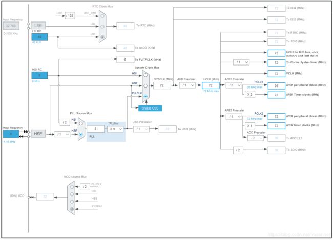
2.2 Clock Configuration
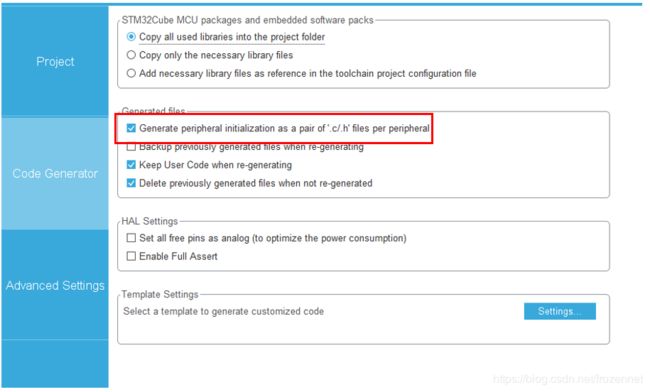
2.3 Project Manager
3. 程序代码
3.1 usart.c
3.2 main.c
4. 程序分析
4.1 主要功能
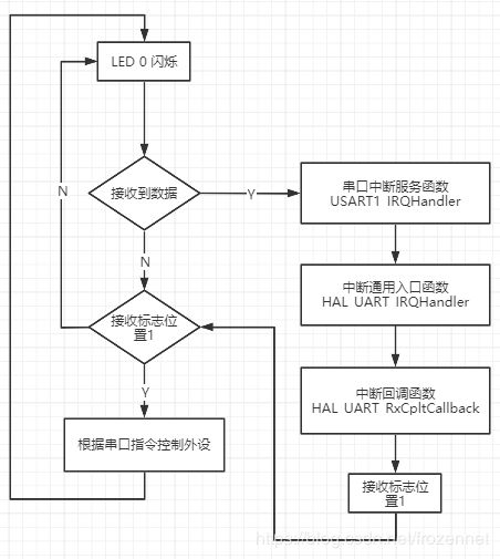
4.2 程序流程
4.3 主要函数
1. 软件与硬件
1.1 硬件要求:
(1)ALIENTEK ELITE STM32F103 开发板 (STM32F103ZET6 芯片)
(2)USB转TTL 模块
1.2 软件要求:
(1)Java Runtime Environment (JRE) 1.8.0 版本
(2)STM32CubeMX 5.6.1 版本
(3)IAR Embedded Workbench 8.0
(4)串口调试工具
2. STM32CubeMX配置开发板
LED 0:PB5
LED 1:PE5
BEEP 蜂鸣器:PB8
USART1_TX:PA9
USART1_RX:PA10
2.1 Pinout & Configuration
(1) GPIO 配置
LED 0、LED1、蜂鸣器设置为Output Push Pull 并设置上拉电阻,使之维持在高电平。
(2) RCC(Reset and Clock Control)时钟控制器配置
(3) USART1 配置
设置为异步模式并使能中断
USART 参数设置
2.2 Clock Configuration
2.3 Project Manager
3. 程序代码
程序下载:https://download.csdn.net/download/frozennet/12587600
3.1 usart.c
实现printf的重定向
/* USER CODE BEGIN 0 */
/******************************************************************
*@brief  Retargets the C library printf  function to the USART.
*@param  None
*@retval None
******************************************************************/
#include "stdio.h"

#ifdef __GNUC__
	#define PUTCHAR_PROTOTYPE int _io_putchar(int ch)
#else
	#define PUTCHAR_PROTOTYPE int fputc(int ch, FILE *f)
#endif /* __GNUC__*/

PUTCHAR_PROTOTYPE
{
  HAL_UART_Transmit(&huart1, (uint8_t *)&ch, 1, 0xFFFF);
  return ch;
}
/* USER CODE END 0 */
3.2 main.c
(1)添加头文件
/* Private includes ----------------------------------------------------------*/
/* USER CODE BEGIN Includes */
#include
#include
/* USER CODE END Includes */
(2)添加预定义
/* Private define ------------------------------------------------------------*/
/* USER CODE BEGIN PD */
/* Uncomment this line to Disable LED Blink*/
//#define LED_BLINK_DISABLE

/* Uncomment this line to Enable LED Blink*/
#define LED_BLINK_ENABLE

#define Uart1_RxBufferSIZE  255     /* Define the size of buffer zone*/
/* USER CODE END PD */
(3)添加变量
/* Private variables ---------------------------------------------------------*/
/* USER CODE BEGIN PV */
__IO ITStatus UartReady = RESET;              /* The flag of interruption*/
char Uart1_RxBuffer[Uart1_RxBufferSIZE];      /* The buffer zone */
uint8_t RxBuffer_IT;			      /* Receive a byte of data */
uint8_t Uart1_Rx_Count = 0;		      /* Count for receiving */

#ifdef LED_BLINK_ENABLE
uint32_t Prior_Tick = 0;                      /* Record prior tick */
uint32_t Current_Tick = 0;                    /* Record current tick */
uint32_t Delay_Time = 100;                    /* Delay time needed */
#endif
/* USER CODE END PV */
(4)接收第一个字符,并判断是否接收正确
  /* USER CODE BEGIN 2 */
  /* Receive the first character */
  printf("Hello world\r\n");
  if(HAL_UART_Receive_IT(&huart1, (uint8_t *)&RxBuffer_IT, 1)== HAL_OK)
  {
  }
  /* USER CODE END 2 */
(5)程序主体
  /* Infinite loop */
  /* USER CODE BEGIN WHILE */
  while (1)
  {

#ifdef LED_BLINK_ENABLE
    Current_Tick = HAL_GetTick();             /* Get current system tick */

    if(Current_Tick < Prior_Tick)             /* System overflow */
    {
      if(HAL_MAX_DELAY - Prior_Tick + Current_Tick == Delay_Time)
      {
        HAL_GPIO_TogglePin(GPIOB, GPIO_PIN_5);
        Prior_Tick = Current_Tick;
        printf("Break down\n");
      }
    }

    if(Current_Tick-Prior_Tick == Delay_Time)     /* Satisfy delay */
    {
      HAL_GPIO_TogglePin(GPIOB, GPIO_PIN_5);      /* Change LED0 status */
      Prior_Tick = Current_Tick;                  /* Update prior tick with current tick */
    }
#endif

    /* UartReady SET by HAL_UART_RxCpltCallback */
    if(UartReady == SET)
    {
      UartReady = RESET;
      if(Uart1_Rx_Count >= Uart1_RxBufferSIZE)                          /* Judge for the overflow of buffer zone */
      {
        Uart1_Rx_Count = 0;                                             /* Reset the count for receiving */
        memset(Uart1_RxBuffer,0x00,sizeof(Uart1_RxBuffer));             /* Re-memorize the buffer zone */
      }
      Uart1_RxBuffer[Uart1_Rx_Count] = RxBuffer_IT;                     /* Save a character in the array */
      HAL_UART_Transmit(&huart1, (uint8_t *)&RxBuffer_IT, 1, 0xFFFF);
      Uart1_Rx_Count++;
      HAL_UART_Receive_IT(&huart1, (uint8_t *)&RxBuffer_IT, 1);         /* Continue to receiving */

      if((Uart1_RxBuffer[Uart1_Rx_Count-4] == 0x30)&& (Uart1_RxBuffer[Uart1_Rx_Count-2] == 0x0D) && (Uart1_RxBuffer[Uart1_Rx_Count-1] == 0x0A))
      {
        switch(Uart1_RxBuffer[Uart1_Rx_Count-3])
        {
#ifdef LED_BLINK_DISABLE
          case 0x31:
            HAL_GPIO_TogglePin(GPIOB, GPIO_PIN_5);      /* Change LED0 status */
            break;
#endif
          case 0x32:
            HAL_GPIO_TogglePin(GPIOE, GPIO_PIN_5);      /* Change LED1 status */
            break;
          case 0x33:
            HAL_GPIO_TogglePin(GPIOB, GPIO_PIN_8);      /* Buzzer open */
            HAL_Delay(500);
            HAL_GPIO_TogglePin(GPIOB, GPIO_PIN_8);      /* Buzzer close */
            HAL_Delay(3000);
            HAL_GPIO_TogglePin(GPIOB, GPIO_PIN_8);      /* Buzzer open */
            HAL_Delay(500);
            HAL_GPIO_TogglePin(GPIOB, GPIO_PIN_8);      /* Buzzer close */
            break;
          default:
            break;
        }
        Uart1_Rx_Count = 0;
        memset(Uart1_RxBuffer,0x00,sizeof(Uart1_RxBuffer));
      }
    } /* end if*/
  } /* end while*/
  /* USER CODE END WHILE */
(6)回调函数
/* USER CODE BEGIN 4 */
/* UART receives completely callback */
void HAL_UART_RxCpltCallback(UART_HandleTypeDef *huart)
{
  UartReady = SET;      /* Reset the flag of interruption */
}

/* USER CODE END 4 */
4. 程序分析
4.1 主要功能
通过串口通讯接收指令,控制 LED 和蜂鸣器,指令采取16进制,同时开发板串口并返回接收到的信息。
(1)指令集
30 31 0D 0A:控制 LED 0
30 32 0D 0A:控制 LED 1
30 33 0D 0A:控制蜂鸣器
(2)通过预定义控制 LED 0是否保持闪烁
不闪烁,接受串口控制
/* Uncomment this line to Disable LED Blink*/
#define LED_BLINK_DISABLE
保持闪烁,不接受串口控制
/* Uncomment this line to Enable LED Blink*/
#define LED_BLINK_ENABLE
4.2 程序流程
4.3 主要函数
(1)HAL_UART_Transmit_IT
(2)HAL_UART_Receive_IT


