//FPGA做主机,数模转换器(DAC)芯片做从机,实现SPI接口的配置(SPI串行外设接口)
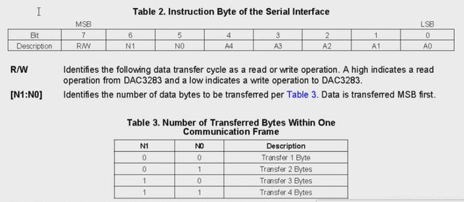
//该DAC芯片的SPI配置的寄存器是8位的
//第7位是读写选择信号,读信号高有效,写信号低有效
//第6位和第5位是读写几个BYTE的定义,00(1个BYTE);01(2个BYTE);10(3个BYTE);11(4个BYTE)
//第4~0位,是要操作的目标寄存器的地址
module spi_crl(
input wire sclk,//系统时钟50MHz,使用该时钟做全局时钟
input wire rst_n,//复位信号
input wire work_en,//模块工作的使能端
output reg conf_end,//配置结束的标志
output wire spi_clk,//SPI的时钟,一般是50MHz到60MHz,
output wire spi_sdi,//SPI的输入数据(由从机输出到主机)
output wire spi_csn,//SPI的片选信号,低有效
input wire spi_sdo//SPI的输出(由主机输出到从机),暂时不进行考虑,不使用
);
//将sclk与spi_sdo的中心对齐,是建立时间和保持时间达到最大,有充足的裕量,确保满足建立时间和保持时间。
//采用状态机来描述
parameter IDLE = 5
parameter WAIT = 5
parameter R_MEM = 5
parameter W_REG = 5
parameter STOP = 5
parameter H_DIV_CYC = 5
//实现过程中涉及到的一些寄存器
reg [4:0] state;//状态机的寄存器变量,采用独热码
reg [4:0] div_cnt;//用来分频的计数器
reg clk_p;//正向时钟,与分频后的时钟有关,也有一个180°的相位
wire clk_n;//反向时钟,也就是clk_p的反向,即没有相位的改变,这个才是SPI的时钟。
reg pose_flag;//上升沿的标志位,用于分频同步
reg [3:0] wait_cnt;//等待时间的计数器,产生等待时间。
reg [3:0] shift_cnt;//数据结束的计时,也就是数据接收完后进入下一个状态
reg [4:0] r_addr;//读地址
wire [15:0] r_data;//读的数据
wire wren;//写使能信号
reg [15:0] shift_buf;
//定义一个串行数据的缓存器,即shift_buf,是在读完数据后(R_MEM状态后)进行缓存,但是在W_REG状态时才完成赋,因为有一个时钟的延时。
reg data_end;//32位数据写入结束的标志
reg sdi;//用来给spi_sdi赋值
reg csn;//用来给spi_csn赋值
reg tclk;//用来给spi_clk赋值
//以下是实现的过程
//分频器的实现,分频为1M的时钟;
always @(posedge sclk or negedge rst_n)
if(rst_n == 1
div_cnt <= 5
else if(div_cnt == H_DIV_CYC)
div_cnt <= 5
else
div_cnt <= div_cnt + 1
//clk_p的产生,即一个方波,
//分频时钟不允许做及寄存器的触发时钟,也就是不能出现在always块的触发列表中
always @(posedge sclk or negedge rst_n)
if(rst_n == 1
clk_p <= 1
else if(div_cnt == H_DIV_CYC)
clk_p <= ~clk_p;
//时钟取反得到SPI的时钟
//这里解释取反的原因,因为在sclk的上升沿时钟有效,即可以认为sclk的0时刻是一个上升沿,但是clk_p的上升沿是在计数到24后也就是25个时钟后的地方,与sclk的上升沿没有对齐,根据波形可以知道,取反后,即clk_n=~clk_p,实现了sclk和spi_clk的同步。
assign clk_n = ~clk_p;
//上升沿的标志位的产生,用于分频同步
always @(posedge sclk or negedge rst_n)
if(rst_n == 1
pose_flag <= 1
else if(clk_p == 1
pose_flag <= 1
else
pose_flag <= 1
//等待时间的产生
always @(posedge sclk or negedge rst_n)
if(rst_n == 1
wait_cnt <= 4
else if(state == WAIT && pose_flag == 1
wait_cnt <= wait_cnt + 1
else if(state
wait_cnt <= 4
//状态机的描述
always @(posedge sclk or negedge rst_n)
if(rst_n == 1
state <= IDLE;
else case(state)
IDLE:if(work_en == 1
state <= WAIT;
WAIT:if(wait_cnt[3] == 1
state <= R_MEM;
R_MEM:state <= W_REG;//这里不需要等待,读出来后就可以写入数据
W_REG:if(shift_cnt == 4
state <= WAIT;
else if(shift_cnt == 4
state <= STOP;
STOP: state <= STOP;
default: state <= IDLE;
endcase
//shift_cnt的定义,也就是每一条命令的时间
always @(posedge sclk or negedge rst_n)
if(rst_n == 1
shift_cnt <= 4
else if(state == W_REG && pose_flag == 1
shift_cnt <= shift_cnt + 1
else if(state
shift_cnt <= 4
//读memory的地址的产生
always @(posedge sclk or negedge rst_n)
if(rst_n == 1
r_addr <=5
else if(state == R_MEM)
r_addr <= r_addr + 1
assign wren = 1
//shift_buf的值赋值,
always @(posedge sclk or negedge rst_n)
if(rst_n == 1
shift_buf <= 5
else if(state == R_MEM)//将RAM中读取的数据赋值给shift_buf
shift_buf <= r_data;
else if(state == W_REG && pose_flag == 1
shift_buf <= {shift_buf[14:0],1
//data_end的产生,最后一个需要移位的数据
always @(posedge sclk or negedge rst_n)
if(rst_n == 1
data_end <= 1
else if(state == R_MEM && (&r_addr) == 1
data_end <= 1
//数据的输出
always @(posedge sclk or negedge rst_n)
if(rst_n == 1
sdi <= 1
else if(state == W_REG)
sdi <= shift_buf[15];//将RAM中的数据的读取出来后赋值给寄存器再进行写入
else if(state
sdi <= 1
//片选信号的生成,低有效
always @(posedge sclk or negedge rst_n)
if(rst_n == 1
csn <= 1
else if(state == W_REG)
csn <= 1
else
csn <= 1
//spi_clk的产生,即tclk,在不工作的时候是低电平
always @(posedge sclk or negedge rst_n)
if(rst_n == 1
tclk <= 1
else if(state == W_REG)
tclk <= clk_n;
else
tclk <= 1
//配置结束标志的产生
always @(posedge sclk or negedge rst_n)
if(rst_n == 1
conf_end <= 1
else if(state == STOP)
conf_end <= 1
//进行连线
assign spi_clk = tclk;
assign spi_sdi = sdi;
assign spi_csn = csn;
//例化一个RAM,用来读取数据
ram_16x32_sr ram_16x32_sr_inst (
.address ( r_addr ),//读地址
.clock ( sclk ),
.data ( 16
.wren ( wren ),//写使能高有效,读使能低有效
.q ( r_data )//读数据
);
endmodule
`timescale 1ns/1ns
module tb_ex_spi;
reg sclk;
reg rst_n;
reg work_en;
wire spi_clk;
wire spi_sdi;
wire spi_csn;
reg [15:0] send_mem [31:0];//定义一个memory变量
reg [15:0] shift_buf;

wire spi_sdo;
wire  conf_end;


initial begin
		rst_n=0;
		sclk=0;
		#100;
		rst_n=1;
		end

initial begin
		work_en=0;
	   #150;
	   work_en=1;
	   end

initial begin
		$readmemb("dac_ini_16x32.mif",send_mem);//memory变量的初始化
		end

initial begin
		rec_spi();
		end

always #10 sclk=~sclk;

spi_crl spi_crl_inst(
		.sclk		(sclk)		,
		.rst_n		(rst_n)		,
		.work_en	(work_en)	,
		.conf_end	()		,
		.spi_clk	(spi_clk)		,
		.spi_sdi	(spi_sdi)		,
		.spi_csn	(spi_csn)		,
		.spi_sdo	()	//读输入管脚不进行配置
);

//定义一个任务,用于接收数据,验证写入的数据是否为读取到的数据
task rec_spi();
		integer i,j;
		begin
			for(i=0;i<32;i=i+1)
				begin
					for(j=0;j<16;j=j+1)
						begin
							@(posedge spi_clk);
								shift_buf={shift_buf[14:0],spi_sdi};
							if(j == 15 && shift_buf == send_mem[i])
								$display("ok data index is %d rec_d=%b send_d=%b",i,shift_buf,send_mem[i]);
							else if(j == 15)
								$display("error");
						end
				end
		end

endtask
endmodule
quit -sim
.main clear

vlib work
vmap work work

vlog -work work tb_ex_spi.v
vlog ./../design/spi_ctrl.v
vlog ./../quartus_prj/ipcore_dir/ram_16x32_sr.v
vlog ./altera_lib/*.v

vsim -voptargs=+acc work.tb_ex_spi

add wave  tb_ex_spi/spi_crl_inst/*
add wave  tb_ex_spi/rec_spi/*

run 300us
memory的数据
0000000001110000
0000000100110001
0000001000000000
0000001100010000
0000010011111111
0000010100000000
0000011000000000
0000011100000000
0000100000000000
0000100101010101
0000101010101010
0000101101010101
0000110010101010
0000110101010101
0000000000000000
0000111101010101
0001000010101010
0001000100100100
0001000100000010
0001001111000010
0001010000000000
0001010100000000
0001011000000000
0001011100000100
0001100010000011
0001100100000000
0001101000000000
0001101100000000
0001110000000000
0001110100000000
0001111000100100
0001111101010010
RAM的初始化文件,用.mif文件。
-- Copyright (C) 1991-2013 Altera Corporation
-- Your use of Altera Corporation
-- and other software and tools, and its AMPP partner logic
-- functions, and any output files from any of the foregoing
-- (including device programming or simulation files), and any
-- associated documentation or information are expressly subject
-- to the terms and conditions of the Altera Program License
-- Subscription Agreement, Altera MegaCore Function License
-- Agreement, or other applicable license agreement, including,
-- without limitation, that your use is for the sole purpose of
-- programming logic devices manufactured by Altera and sold by
-- Altera or its authorized distributors. Please refer to the
-- applicable agreement for further details.
-- Quartus II generated Memory Initialization File (.mif)
WIDTH=16;
DEPTH=32;
ADDRESS_RADIX=UNS;
DATA_RADIX=BIN;
CONTENT BEGIN
0 : 0000000001110000;
1 : 0000000100110001;
2 : 0000001000000000;
3 : 0000001100010000;
4 : 0000010011111111;
5 : 0000010100000000;
6 : 0000011000000000;
7 : 0000011100000000;
8 : 0000100000000000;
9 : 0000100101010101;
10 : 0000101010101010;
11 : 0000101101010101;
12 : 0000110010101010;
13 : 0000110101010101;
14 : 0000000000000000;
15 : 0000111101010101;
16 : 0001000010101010;
17 : 0001000100100100;
18 : 0001000100000010;
19 : 0001001111000010;
20 : 0001010000000000;
21 : 0001010100000000;
22 : 0001011000000000;
23 : 0001011100000100;
24 : 0001100010000011;
25 : 0001100100000000;
26 : 0001101000000000;
27 : 0001101100000000;
28 : 0001110000000000;
29 : 0001110100000000;
30 : 0001111000100100;
31 : 0001111101010010;
END;
寄存器的配置

 状态转移图:
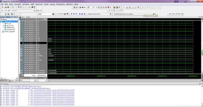
 modelsim仿真结果:


