数字IC笔试——乐鑫提前批笔试编程题源码
网上有很多乐鑫的笔试原题与部分答案,我就不重复了,这里主要针对编程题进行讲解与源码提供,如有不当或者错误欢迎指正。
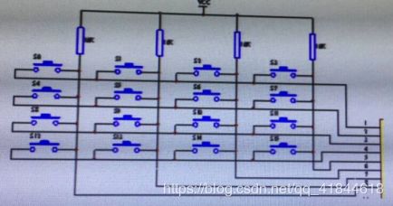
1、请实现对4*4矩阵式健盘的按键识别

由图可知,键盘的每一列通过一个上拉电阻,接到VCC。在检测有没有按键按下时,我们可以,先使行线同时为0,直到有一根列线被下拉到0。这时知道,有按键按下,但并不知道,是列线的确切位置。我们可以,扫描每一个列线,直到发现列线的位置。状态转换图如下图所示:

在S_0状态,所有的行被置为0,当S_col为(有一个列被置为0)1时,到S_1状态。S_1状态只有第一行为低电平,其余为高电平,检测是否有列为高电平,如果S_col为1则跳转到S_5,等待按键释放,如果S_col为0,进入S_2状态开始检测第二行。
代码如下:
同步模块
module Synchronizer(output reg S_col,input[3:0]col,input clk,rst);
	reg A_col;

	always@(posedge clk,posedge rst)
	begin
		if (rst==1'b1) begin A_col<=1'b0;S_col<=1'b0; end
		else begin
			A_col<=(col[0]&&col[1]&&col[2]&&col[3]);
			S_col<=A_col;
		end
	end
endmodule
列信号产生模块
module col_Signal (output reg[3:0]col,input [15:0]Key,input[3:0]row);

	//扫描有效键所在列
	always@(Key,row)
	begin
		col[0]=(Key[0]&&row[0])||(Key[1]&&row[1])||(Key[2]&&row[2])||(Key[3]&&row[3]);
		col[1]=(Key[4]&&row[0])||(Key[5]&&row[1])||(Key[6]&&row[2])||(Key[7]&&row[3]);
		col[2]=(Key[8]&&row[0])||(Key[9]&&row[1])||(Key[10]&&row[2])||(Key[11]&&row[3]);
		col[3]=(Key[12]&&row[0])||(Key[13]&&row[1])||(Key[14]&&row[2])||(Key[15]&&row[3]);
	end
endmodule
键盘信号产生
module Hex_Keypad_Grayhill_072(
	output reg[3:0] Code,row,
	input [3:0]	col,
	input		S_col,clk,rst
	);

	reg [5:0] state,next_state;

	parameter S_0=6'b000001,S_1=6'b000010,S_2=6'b000100;
	parameter S_3=6'b001000,S_4=6'b010000,S_5=6'b100000;


	always@(row,col)
		case ({row,col})
			8'b0001_0001:	Code=4'b0000;
			8'b0001_0010:	Code=4'b0001;
			8'b0001_0100:	Code=4'b0010;
			8'b0001_1000:	Code=4'b0011;
			8'b0010_0001:	Code=4'b0100;
			8'b0010_0010:	Code=4'b0101;
			8'b0010_0100:	Code=4'b0110;
			8'b0010_1000:	Code=4'b0111;
			8'b0100_0001:	Code=4'b1000;
			8'b0100_0010:	Code=4'b1001;
			8'b0100_0100:	Code=4'b1010;
			8'b0100_1000:	Code=4'b1011;
			8'b1000_0001:	Code=4'b1100;
			8'b1000_0010:	Code=4'b1101;
			8'b1000_0100:	Code=4'b1110;
			8'b1000_1000:	Code=4'b1111;
			default:		Code=4'b0000;
		endcase

	always@(posedge clk, posedge rst)
		if (reset==1'b1) state<=S_0;
		else state<=next_state;

	always@(state,S_Row,Row)
		begin next_state=S_0;row=4'b1111;
		case (state)
			S_0: begin
				row=4'b0000;
				if (S_col) next_state=S_1;
				else next_state=S_0;
			end
			S_1: begin
				row=4'b0001;
				if (col!=4'b1111) next_state=S_5;
				else next_state=S_2;
			end
			S_2: begin
				row=4'b0010;
				if (col!=4'b1111) next_state=S_5;
				else next_state=S_3;
			end
			S_3: begin
				row=4'b0100;
				if (col!=4'b1111) next_state=S_5;
				else next_state=S_4;
			end
			S_4: begin
				row=4'b1000;
				if (col!=4'b1111) next_state=S_5;
				else next_state=S_0;
			end
			S_5: begin
				row=4'b1111;
				if (col==4'b1111) next_state=S_0;
				else next_state=S_5;
			end
			default: next_state=S_0;
		endcase
		end
		endmodule
2、用Verilog实现CRC-8的串行计算,G(D)=D8+D2+D1+1

可以划分两个模块去实现,一个为控制电路,由状态机实现,一个为数据通路,由LSFR以及计数器实现。
代码如下:
控制模块
module control(

	input clk,rst_n,
	input crc_start,
	input [5:0]crc_cnt,
	input [3:0]cnt_out,
	output reg crc_valid,
	output reg shift,
	output reg se_out
	);

	localparam 	SIDLE=3'b001,
				SSHIFT=3'b010,
				SOUT=3'b100;

	reg [2:0] current_state,next_state;

	always @ (posedge clk or negedge rst_n)
	begin
		if (!rst_n)
			current_state<=SIDLE;
		else
			current_state<=next_state;
	end

	always @ (*)
	begin
		next_state=current_state;
		case (current_state)
			SIDLE:begin
					if (crc_start)
						next_state=SSHIFT;
				end

			SSHIFT:begin
					if (crc_cnt==6'd32)
						next_state=SOUT;
					else
						next_state=SSHIFT;
				end
			SOUT:begin
					if (cnt_out==4'd8)
						next_state=SIDLE;
					else
						next_state=SOUT;
				end
			default:next_state=SIDLE;
		endcase
	end

	always @ (*)
	begin
		shift=1'b0;
		crc_valid=1'b0;
		se_out=1'b0;
		case(current_state)
			SSHIFT:	shift=1'b1;
			SOUT:	begin
						if (cnt_out==4'd8)
							crc_valid=1'b1;
						else
							se_out=1'b1;
					end
			default:begin
						shift=1'b0;
						crc_valid=1'b0;
						se_out=1'b0;
					end
		endcase
	end
	endmodule
数据通路模块:
module datapath(
	input seria_in,
	input clk,rst_n,
	input shift,se_out,
	output reg [3:0] cnt_out,
	output reg [5:0] crc_cnt,
	output reg seria_out
	);
	reg [7:0] C;

	always @ (posedge clk or negedge rst_n)
	begin
		if (!rst_n) begin
			C<=8'b1111_1111;
			seria_out<=1'b1;
		end
		else if (shift) begin
			C[0]<=C[7]^seria_in;
			C[1]<=C[0]^(C[7]^seria_in);
			C[2]<=C[1]^(C[7]^seria_in);
			C[3]<=C[2];
			C[4]<=C[3];
			C[5]<=C[4];
			C[6]<=C[5];
			C[7]<=C[6];
			seria_out<=1'b1;
		end
		else if (se_out) begin
			C<={C[6:0],C[7]};
			seria_out<=C[7];
		end
	end

	always @ (posedge clk or negedge rst_n)
	begin
		if (rst_n)
			cnt_out<=4'b0;
		else if (cnt_out==4'b1000)
			cnt_out<=4'b0;
		else
			cnt_out<=cnt_out+1'b1;
	end

	always @ (posedge clk or negedge rst_n)
	begin
		if (rst_n)
			cnt_out<=6'b0;
		else if (cnt_out==4'd32)
			cnt_out<=6'b0;
		else
			cnt_out<=cnt_out+1'b1;
	end

endmodule