Gazebo中添加Kinect相机并通过Canny边缘检测识别计算空间点坐标
Github地址https://github.com/KL-Lee/Showimg.git
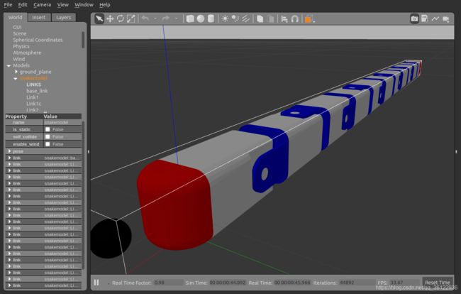
最近在做机器人项目,使用ROS+Gazebo仿真环境,首先在蛇型机器人的头部添加Kinect深度相机模型。打开模型的urdf文件。添加深度相机模块。代码如下所示:
            30.0

                1.3962634

                    640
                    480
                    R8G8B8


                    0.02
                    300


                true
                10
                camera
                rgb/image_raw

                depth/image_raw
		depth/points
                rgb/camera_info
		depth/camera_info
                camera_depth_optical_frame
                0.1
		0.0
		0.0
		0.0
		0.0
		0.0
                0.4
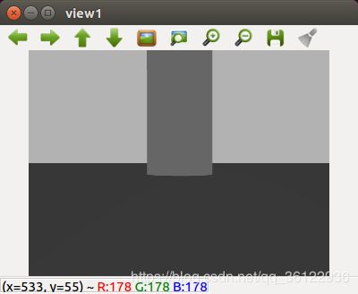
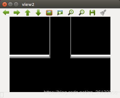
有了相机模型后,就可以直接通过ROS订阅相机RGB图像节点rgb/image_raw和深度图像节点depth/image_raw来观察相机图像信息。也可以直接运行rqt_image_view命令。我这里由于要对图像进行处理,所以使用的是自己写返回函数。订阅节点与边缘检测代码如下所示:
#include
#include
#include
#include
#include
#include
#include
#include


using namespace cv;
using namespace std;

Mat colorImg;
Mat depthImg;
int flag = 1 ;

Mat src;
Mat src_gray;
int thresh = 30;
int max_thresh = 255;

int getpix(string imgstr);

void imageCallbackrgb(const sensor_msgs::ImageConstPtr& msg)
{
  try
  {


    cv_bridge::CvImagePtr cv_ptr;
    cv_ptr = cv_bridge::toCvCopy(msg, sensor_msgs::image_encodings::BGR8);
    colorImg = cv_ptr->image;
    imshow("view1",colorImg);


    if (flag)
    {
      imwrite("/home/lee/catkin_ws/src/showimg/build/test_results/color.png",colorImg);
      const string imgpath = "/home/lee/catkin_ws/src/showimg/build/test_results/color.png";
      getpix ( imgpath );
      flag = 0;
    }
    cv::waitKey(1);
  }
  catch (cv_bridge::Exception& e)
  {
    ROS_ERROR("Could not convert from '%s' to 'bgr8'.", msg->encoding.c_str());
  }
}

void imageCallbackdepth(const sensor_msgs::ImageConstPtr& msg)
{
  try
  {
    cv_bridge::CvImagePtr cv_ptr;
    cv_ptr = cv_bridge::toCvCopy(msg, sensor_msgs::image_encodings::TYPE_32FC1);
    depthImg = cv_ptr->image;
    imshow("view2",depthImg);

    imwrite("/home/lee/catkin_ws/src/showimg/build/test_results/depth.png",depthImg);

    cv::waitKey(1);
  }
  catch (cv_bridge::Exception& e)
  {
    ROS_ERROR("Could not convert from '%s' to 'bgr8'.", msg->encoding.c_str());
  }
}

int getpix(string imgstr)
{
//	src = imread( "/home/lee/projects/midext/color.png" ,CV_LOAD_IMAGE_COLOR ); 	//注意路径得换成自己的

  src = imread( imgstr ,CV_LOAD_IMAGE_COLOR );
	cvtColor( src, src_gray, CV_BGR2GRAY );//灰度化
	GaussianBlur( src, src, Size(3,3), 0.1, 0, BORDER_DEFAULT );
	blur( src_gray, src_gray, Size(3,3) ); //滤波
	namedWindow( "image", CV_WINDOW_AUTOSIZE );

	imshow( "image", src );
	moveWindow("image",20,20);
	//定义Canny边缘检测图像

	Mat canny_output;
	vector > contours;
	vector hierarchy;
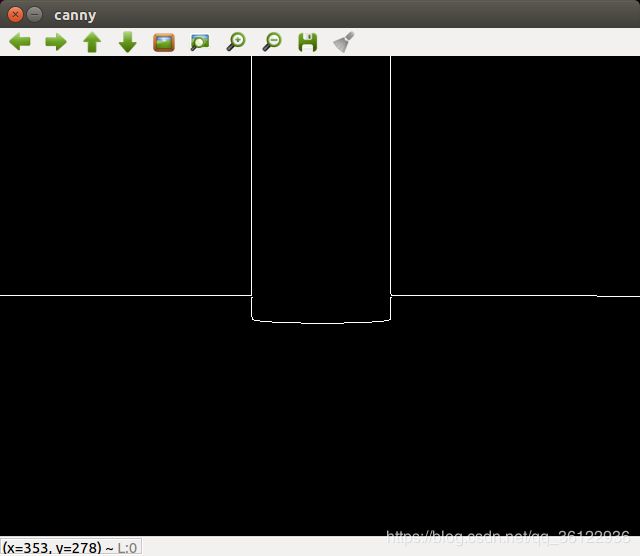
	//利用canny算法检测边缘

	Canny( src_gray, canny_output, thresh, thresh*3, 3 );
	namedWindow( "canny", CV_WINDOW_AUTOSIZE );
	imshow( "canny", canny_output );
	moveWindow("canny",550,20);

	//查找轮廓
	findContours( canny_output, contours, hierarchy, CV_RETR_TREE, CV_CHAIN_APPROX_SIMPLE, Point(0, 0) );
	//计算轮廓矩
	vector mu(contours.size() );

	for( int i = 0; i < contours.size(); i++ )
	{
		mu[i] = moments( contours[i], false );
	}

	//计算轮廓的质心
	vector mc( contours.size() );
	for( int i = 0; i < contours.size(); i++ )
	{
		mc[i] = Point2d( mu[i].m10/mu[i].m00 , mu[i].m01/mu[i].m00 );
	}

	//画轮廓及其质心并显示
	Mat drawing = Mat::zeros( canny_output.size(), CV_8UC3 );
	for( int i = 0; i< contours.size(); i++ )
	{
		Scalar color = Scalar( 255, 0, 0);
		drawContours( drawing, contours, i, color, 2, 8, hierarchy, 0, Point() );
		circle( drawing, mc[i], 5, Scalar( 0, 0, 255), -1, 8, 0 );
		rectangle(drawing, boundingRect(contours.at(i)), cvScalar(0,255,0));
		char tam[100];
		sprintf(tam, "(%0.0f,%0.0f)",mc[i].x,mc[i].y);
		putText(drawing, tam, Point(mc[i].x, mc[i].y), FONT_HERSHEY_SIMPLEX, 0.4, cvScalar(255,0,255),1);
  }

	namedWindow( "Contours", CV_WINDOW_AUTOSIZE );
	imshow( "Contours", drawing );
	moveWindow("Contours",1100,20);
  cout << "mc = :" <
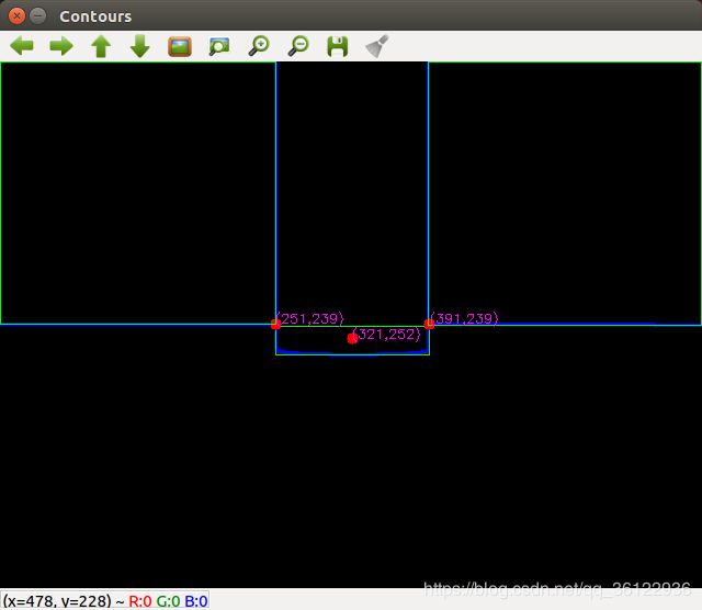
最终效果如下:分别为RGB图,深度图,边缘检测图,质心坐标计算图:
然后结合该点的像素坐标与深度距离d,通过针孔相机模型即可计算出该目标点的三维世界坐标
