Robotics System Toolbox中的机器人运动 (3)
1、前记:在这篇博文之前,已经对RST中机器人的运动方式有了初步的尝试,,如 Robotics System Toolbox中的机器人运动(1)和Robotics System Toolbox中的机器人运动(2)---圆的轨迹跟踪。
正运动方式--->单独控制各关节运动,被控对象--->各个单独关节,控制方式--->各关节变量驱动单轴;
逆运动方式--->控制所有关节协调运动以实现末端姿态,被控对象--->所有关节,控制方式--->所有关节变量协调驱动各关节。
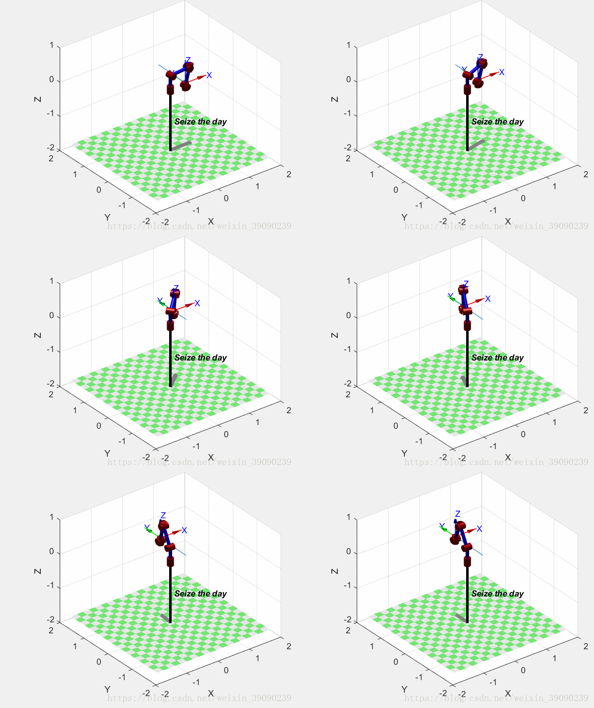
2、在正式开始使用工具箱逆解函数ik(robotics system toolbox)之前,回顾ikine(robotics toolbox 9.10函数)的直线运动。
代码和动图如下:
clc;
clear;
%建立机器人模型
%       theta    d        a        alpha     offset
L1=Link([0       0.4      0.025    pi/2      0     ]); %定义连杆的D-H参数
L2=Link([pi/2    0        0.56     0         0     ]);
L3=Link([0       0        0.035    pi/2      0     ]);
L4=Link([0       0.515    0        pi/2      0     ]);
L5=Link([pi      0        0        pi/2      0     ]);
L6=Link([0       0.08     0        0         0     ]);
robot=SerialLink([L1 L2 L3 L4 L5 L6],'name','Seize the day'); %连接连杆,机器人取名Seize the day
T1=transl(0.5,0,0);%根据给定起始点,得到起始点位姿
T2=transl(0,0.5,0.5);%根据给定终止点,得到终止点位姿
T=ctraj(T1,T2,50);%组成50个点构成笛卡尔轨迹
Tj=transl(T);%取50个位姿点的空间位置坐标x,y,z
plot3(Tj(:,1),Tj(:,2),Tj(:,3));%输出末端轨迹
grid on;
q=robot.ikine(T);%调用ikine得到各关节角度的配置以实现末端位置
hold on
robot.plot(q);%动画演示
3、利用IK和Curve Fitting Toolbox的直线轨迹运动。
%% Waypoint tracking demonstration using Robotics System Toolbox
% This demonstration performs inverse kinematics of a
% robot manipulator to follow a desired set of waypoints.
% Copyright 2017-2018 The MathWorks, Inc.
%% Load and display robot导入机器人
clear
clc
robot = importrobot('irb_140.urdf');
axes = show(robot);
axes.CameraPositionMode = 'auto';
%% Create a set of desired wayPoints设置点位
wayPoints = [0.5 -0.4 0.6;0.5 0.2 0.6]; % Alternate set of wayPoints
%wayPoints = [0.2 -0.2 0.02;0.15 0 0.28;0.15 0.05 0.2; 0.15 0.09 0.15;0.1 0.12 0.1; 0.04 0.1 0.2;0.25 0 0.15; 0.2 0.2 0.02];
exampleHelperPlotWaypoints(wayPoints);
%% Create a smooth curve from the waypoints to serve as trajectory
trajectory = cscvn(wayPoints');%在点之间创建轨迹
% Plot trajectory spline and waypoints
hold on
fnplt(trajectory,'r',2);

%% Perform Inverse Kinematics for a point in space
% Add end effector frame, offset from the grip link frame逆运动求解各关节配置
eeOffset = 0.01;
eeBody = robotics.RigidBody('end_effector');
setFixedTransform(eeBody.Joint,trvec2tform([eeOffset 0 0]));
addBody(robot,eeBody,'link_6');
ik = robotics.InverseKinematics('RigidBodyTree',robot);
weights = [0.1 0.1 0 1 1 1];
initialguess = robot.homeConfiguration;
% Calculate the inverse kinematic solution using the "ik" solver
% Use desired weights for solution (First three are orientation, last three are translation)
% Since it is a 4-DOF robot with only one revolute joint in Z we do not
% put a weight on Z rotation; otherwise it limits the solution space
numTotalPoints =40;
% Evaluate trajectory to create a vector of end-effector positions
eePositions = ppval(trajectory,linspace(0,trajectory.breaks(end),numTotalPoints));
% Call inverse kinematics solver for every end-effector position using the
% previous configuration as initial guess
for idx = 1:size(eePositions,2)
    tform = trvec2tform(eePositions(:,idx)');
    configSoln(idx,:) = ik('end_effector',tform,weights,initialguess);
    initialguess = configSoln(idx,:);
end
%% Visualize robot configurations动画显示
title('Robot waypoint tracking visualization')
hold on
axis([-0.6 0.8 -0.6 0.65 0 1.3]);
for idx = 1:size(eePositions,2)
    show(robot,configSoln(idx,:), 'PreservePlot', false,'Frames','off');
    pause(0.1)
end
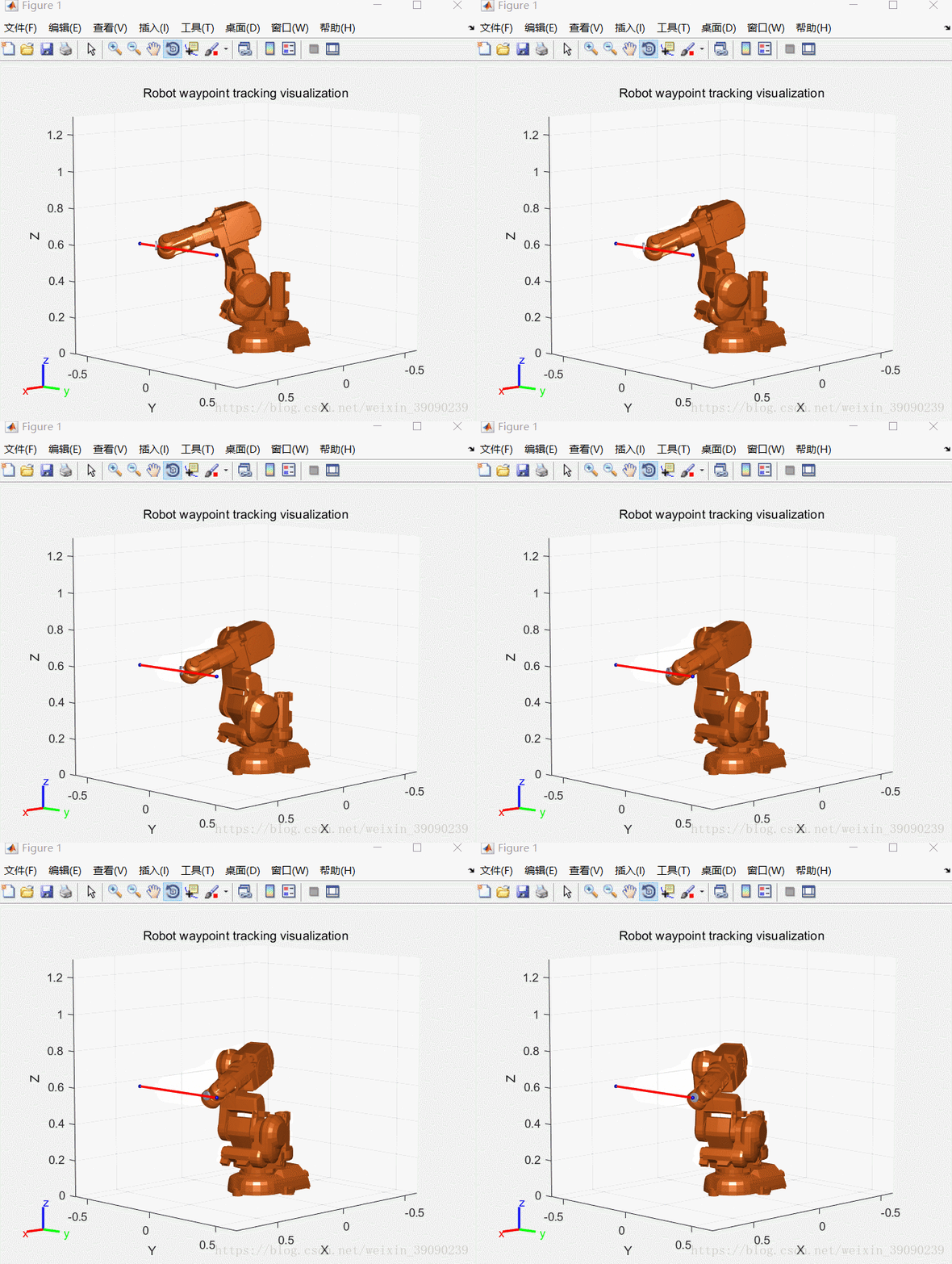
结果:用ABB机器人irb140验证其正确性!

