带测试向量文件的Testbench的编写
项目简介:
高效的编写测试程序对复杂模块的测试十分重要。相对于测试信号有多种可能性的模块,编写带测试向量文件的测试程序能极大提高模块测试的效率。本篇文章以上一篇文章中的8位带进位全加器的测试为例编写带测试向量文件的测试程序,同时也可以比较两种测试方式的优劣。
代码实现:
/*--------------------------------------------------------------
Filename: adder_8.v
Function: 实现两个8位二进制数的带进位加法运算(输出和S最大为256)
Author: Zhang Kaizhou
Date: 2019-10-8 19:45:46
--------------------------------------------------------------*/
//8位加法器顶层模块
module adder_8(s, cout, a, b, cin);
	//输入输出端口及变量定义
	output [7 : 0] s;
	output cout;
	input [7 : 0] a, b;
	input cin;
	wire [6 : 0] carry;

	//采用结构描述的方式实现一个8位加法器
	fulladder m0(s[0], carry[0], a[0], b[0], cin);
	fulladder m1(s[1], carry[1], a[1], b[1], carry[0]);
	fulladder m2(s[2], carry[2], a[2], b[2], carry[1]);
	fulladder m3(s[3], carry[3], a[3], b[3], carry[2]);
	fulladder m4(s[4], carry[4], a[4], b[4], carry[3]);
	fulladder m5(s[5], carry[5], a[5], b[5], carry[4]);
	fulladder m6(s[6], carry[6], a[6], b[6], carry[5]);
	fulladder m7(s[7], cout, a[7], b[7], carry[6]);
endmodule

//1位全加器模块
module fulladder(s, cout, a, b, cin);
	//输入输出端口定义
	output s, cout;
	input a, b, cin;

	//采用行为描述的方式实现1位全加器
	assign s = a ^ b ^ cin;
	assign cout = a & b | a & cin | b & cin;
endmodule
/*------------------------------------------------
Filename: adder_8_t.v
Function: 测试adder_8模块逻辑功能(带测试向量文件)
Author: Zhang Kaizhou
Date: 2019-10-8 19:45:56
-------------------------------------------------*/
`timescale 1ns/1ns
`define PERIOD 5
module adder_8_t(s, cout);
	//端口及变量定义
	output [7 : 0] s;
	output cout;
	reg [7 : 0] a, b, sexpected;
	reg cin, coutexpected, clk;
	reg [25 : 0] testvectors [100 : 0]; //定义101个长度为26bit的测试向量存储单元
	reg [9 : 0] vectornum, errors; //定义两个最大值为1024的寄存器型变量用于计数

	//实例化待测模块
	adder_8 m0(.s(s), .cout(cout), .a(a), .b(b), .cin(cin));

	//产生周期为2 * PERIOD的时钟信号
	always
	begin
		clk = 0;
		#`PERIOD clk = ~clk;
	end

	//从测试文件中读入测试向量到存储单元中
	initial
	begin
		$readmemb("adder_8_data.tv", testvectors);
		vectornum = 0; errors = 0;
	end

	//时钟上升沿加载测试向量到各测试信号变量中
	always@(posedge clk)
	begin
		{a, b, cin, sexpected, coutexpected} = testvectors[vectornum];
	end

	//时钟下降沿判断测试模块输出是否与预期输出一致
	always@(negedge clk)
	begin
		if(s !== sexpected | cout !== coutexpected)
		begin
			$display("Error: inputs = %b", {a, b, cin});
			$display("outputs = %b (%b expected)", {s, cout}, {sexpected, coutexpected});
			errors = errors + 1;
		end
		vectornum = vectornum + 1;
		if(testvectors[vectornum] === 26'bx)
		begin
			$display("%d tests completed with %d errors", vectornum, errors);
			$stop;
		end
	end
endmodule
以下为测试向量文件(文件名:adder_8_data.tv):
00000000_00000000_0_00000000_0
00000001_00000001_1_00000011_0
00100000_00100011_1_01000100_0
11111100_00000011_0_11111111_0
11111100_00000011_1_00000000_1
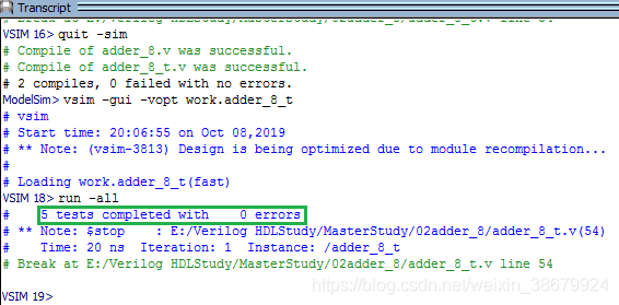
ModelSim仿真结果:

总结:
由上面的仿真结果可知,5组测试信号的输出与测试向量中的预期输出是一致的,所以可以认为该带进位8位全加器的逻辑功能是正确的(为了避免测试向量文件过大,此处并未完全遍历所以的输入可能性)。与上一篇以波形图测试方式相比,在输入测试信号较多时,显然以测试向量的方式进行仿真效率更高些。其中的测试向量往往具有规律性,可采用编程的方式(Matlabe C等)来获得。