STM32H743Nucleo ADC使用DMA配置无法读取数据的问题及解决
STM32H743Nucleo ADC使用DMA配置无法读取数据的问题及解决
- 一、对ADC进行配置
- 二、对程序进行修改
- 三、程序执行结果
- 四、问题解决
一、对ADC进行配置
- 使用STM32H743Nucleo板使用DMA对ADC进行采样实验。
- 对H743Nucleo通过STM32CubeMX(Version 5.0.1 STM32Cube V1.0)进行配置。
- 代码编译器选择KeilMDK (V2.25.2.0)。
- 首先对管脚进行默认初始化。
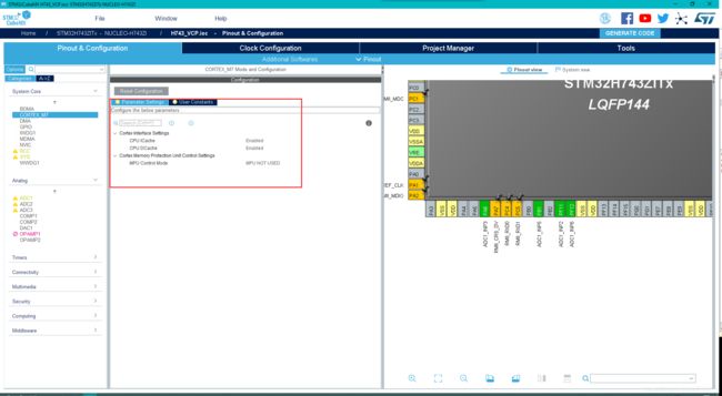
- 对CPU Cache进行使能,如下图:
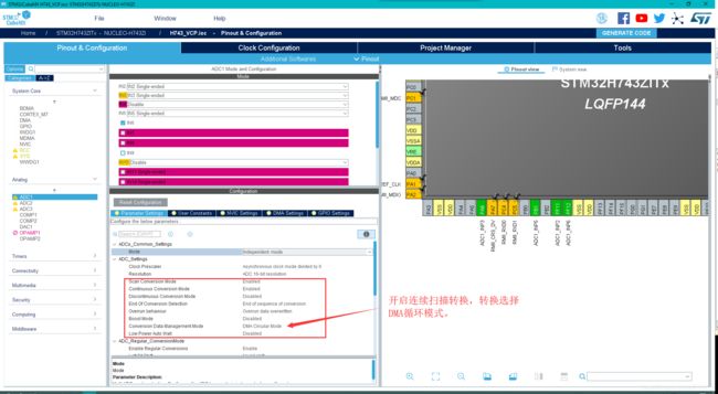
 3.配置ADC,使用ADC1 通道选择了2 、3、5、6四路,如下图:
 4.在ADC的配置中选择连续扫描和转换模式,数据存储选择DMA Circular Mode,如下图:
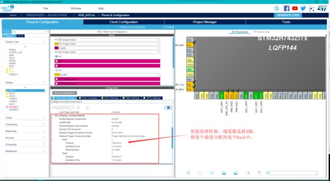
 5.将转换通道数改为4,将每个通道分别写入到每个队列中。
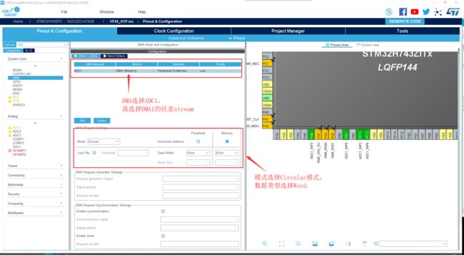
 6.接下来配置DMA:
DMA选择ADC1,选择DMA1的任意流即可。
DMA模式选择循环模式,数据类型选择word型,也可以是Half-Word,根据自己的需求。
 7.最后再使能了一下USART3,将AD的转换数据进行回传。其他均默认,不进行修改。
二、对程序进行修改
1.定义ADC接收数组为uint32_t,共200个数据为一组,一个通道50个数据。在生成代码的指定位置写入自己的程序:
/* USER CODE BEGIN PD */
#define ADC_CONVERTED_DATA_BUFFER_SIZE ((uint32_t)  200)
/* USER CODE END PD */
/* Private variables ---------------------------------------------------------*/
uint32_t ADC_DATA[ADC_CONVERTED_DATA_BUFFER_SIZE] ;
/* USER CODE END PV */
2.在主函数进行数据定义临时数据存放每个通道的AD转换值:
/* USER CODE BEGIN 1 */
uint32_t ad1,ad2,ad3,ad4;
uint16_t i;
/* USER CODE END 1 */
3.采用DMA模式开启ADC的转换,转换数据存在定义的ADC_DATA中:
/* USER CODE BEGIN 2 */
if (HAL_ADC_Start_DMA(&hadc1, (uint32_t *)ADC_DATA, ADC_CONVERTED_DATA_BUFFER_SIZE) != HAL_OK)
{

	Error_Handler();
}
/* USER CODE END 2 */
4.在while循环中对ADC的数据进行读取,并进行50次的均值滤波,最后通过串口进行输出:
/* USER CODE BEGIN 3 */
for(i = 0,ad1=0,ad2=0,ad3=0,ad4=0; i < ADC_CONVERTED_DATA_BUFFER_SIZE;)
{

	ad1 += ADC_DATA[i++];
	ad2 += ADC_DATA[i++];
	ad3 += ADC_DATA[i++];
	ad4 += ADC_DATA[i++];
}
ad1 /= 50;		//累加50次,最后求均值
ad2 /= 50;
ad3 /= 50;
ad4 /= 50;
printf("\r\n******** ADC DMA Example ********\r\n\r\n");
printf(" AD1 value = %1.3fV \r\n", ad1*3.3f/65536);		//转换后的真实电压值
printf(" AD2 value = %1.3fV \r\n", ad2*3.3f/65536);
printf(" AD3 value = %1.3fV \r\n", ad3*3.3f/65536);
printf(" AD4 value = %1.3fV \r\n", ad4*3.3f/65536);
HAL_Delay(500);
/* USER CODE END 3 */
5.将每次ADC转换一半及转换完成后的数据值存放在ADC_DATA中,通过调用HAL_ADC_ConvHalfCpltCallback和HAL_ADC_ConvCpltCallback进行处理。
/* USER CODE BEGIN 4 */
/**
  * @brief  Conversion complete callback in non-blocking mode
  * @param  hadc: ADC handle
  * @retval None
  */
void HAL_ADC_ConvHalfCpltCallback(ADC_HandleTypeDef* hadc)
{

  /* Invalidate Data Cache to get the updated content of the SRAM on the first half of the ADC converted data buffer: 32 bytes */
  SCB_InvalidateDCache_by_Addr((uint32_t *) &ADC_DATA[0], ADC_CONVERTED_DATA_BUFFER_SIZE);
}

/**
 * @brief  Conversion DMA half-transfer callback in non-blocking mode
 * @param  hadc: ADC handle
 * @retval None
  */
void HAL_ADC_ConvCpltCallback(ADC_HandleTypeDef* hadc)
{

   /* Invalidate Data Cache to get the updated content of the SRAM on the second half of the ADC converted data buffer: 32 bytes */
  SCB_InvalidateDCache_by_Addr((uint32_t *) &ADC_DATA[ADC_CONVERTED_DATA_BUFFER_SIZE/2], ADC_CONVERTED_DATA_BUFFER_SIZE);
}
/* USER CODE END 4 */
三、程序执行结果
- 通过串口对数据进行显示,通过这样的DMA采集ADC数据失败,然而通过普通采样模式和中断模式采集ADC均可以采集成功。如图所示:

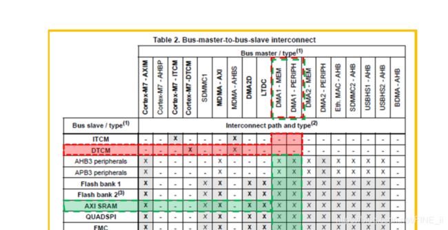
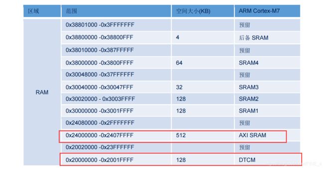
- 最后查找资料发现是STM32CubeMX配置完成后生成的程序执行地址是从RAM 0x20000000开始执行,然而0x20000000是DTCM段,DMA无法进行访问,所以修改ADC存储数据位置为0x24000000即AXI SRAM,此处DMA可以进行访问。
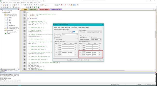
- 下图是默认KeilMDK程序执行的的起始地址
四、问题解决
- 通过上述分析,问题产生的原因在于 DMA1 访问了无法访问到的地址。介绍两种解决方法:
- 方法一,通过原因分析中描述的方法,通过在工程中,指定 RAM 使用空间实现目标地址(访问的数组)在支持的 RAM 区域。
- 方法二,通过在数组定义时,强制分配至支持的 RAM 空间区域,如下所示。
uint32_t ADC_DATA[ADC_CONVERTED_DATA_BUFFER_SIZE] __attribute__((section(".ARM.__at_0x24000000")));
- 其中 attribute((section(".ARM.__at_address")))是被 MDK-ARM 支持的,指定对应空间的方式。
- 通过以上方法的修改,将程序下载后可以观察到DMA存储ADC数据正常:

最后将完整的主程序代码进行上传:
/* USER CODE BEGIN Header */
/**
  ******************************************************************************
  * @file           : main.c
  * @brief          : Main program body
  ******************************************************************************
  ** This notice applies to any and all portions of this file
  * that are not between comment pairs USER CODE BEGIN and
  * USER CODE END. Other portions of this file, whether
  * inserted by the user or by software development tools
  * are owned by their respective copyright owners.
  *
  * COPYRIGHT(c) 2019 STMicroelectronics
  *
  * Redistribution and use in source and binary forms, with or without modification,
  * are permitted provided that the following conditions are met:
  *   1. Redistributions of source code must retain the above copyright notice,
  *      this list of conditions and the following disclaimer.
  *   2. Redistributions in binary form must reproduce the above copyright notice,
  *      this list of conditions and the following disclaimer in the documentation
  *      and/or other materials provided with the distribution.
  *   3. Neither the name of STMicroelectronics nor the names of its contributors
  *      may be used to endorse or promote products derived from this software
  *      without specific prior written permission.
  *
  * THIS SOFTWARE IS PROVIDED BY THE COPYRIGHT HOLDERS AND CONTRIBUTORS "AS IS"
  * AND ANY EXPRESS OR IMPLIED WARRANTIES, INCLUDING, BUT NOT LIMITED TO, THE
  * IMPLIED WARRANTIES OF MERCHANTABILITY AND FITNESS FOR A PARTICULAR PURPOSE ARE
  * DISCLAIMED. IN NO EVENT SHALL THE COPYRIGHT HOLDER OR CONTRIBUTORS BE LIABLE
  * FOR ANY DIRECT, INDIRECT, INCIDENTAL, SPECIAL, EXEMPLARY, OR CONSEQUENTIAL
  * DAMAGES (INCLUDING, BUT NOT LIMITED TO, PROCUREMENT OF SUBSTITUTE GOODS OR
  * SERVICES; LOSS OF USE, DATA, OR PROFITS; OR BUSINESS INTERRUPTION) HOWEVER
  * CAUSED AND ON ANY THEORY OF LIABILITY, WHETHER IN CONTRACT, STRICT LIABILITY,
  * OR TORT (INCLUDING NEGLIGENCE OR OTHERWISE) ARISING IN ANY WAY OUT OF THE USE
  * OF THIS SOFTWARE, EVEN IF ADVISED OF THE POSSIBILITY OF SUCH DAMAGE.
  *
  ******************************************************************************
  */
/* USER CODE END Header */

/* Includes ------------------------------------------------------------------*/
#include "main.h"
#include "adc.h"
#include "dma.h"
#include "usart.h"
#include "gpio.h"

/* Private includes ----------------------------------------------------------*/
/* USER CODE BEGIN Includes */

/* USER CODE END Includes */

/* Private typedef -----------------------------------------------------------*/
/* USER CODE BEGIN PTD */

/* USER CODE END PTD */

/* Private define ------------------------------------------------------------*/
/* USER CODE BEGIN PD */
#define ADC_CONVERTED_DATA_BUFFER_SIZE ((uint32_t)  200)

/* USER CODE END PD */

/* Private macro -------------------------------------------------------------*/
/* USER CODE BEGIN PM */

/* USER CODE END PM */

/* Private variables ---------------------------------------------------------*/

/* USER CODE BEGIN PV */
/* Private variables ---------------------------------------------------------*/
uint32_t ADC_DATA[ADC_CONVERTED_DATA_BUFFER_SIZE] __attribute__((section(".ARM.__at_0x24000000")));


/* USER CODE END PV */

/* Private function prototypes -----------------------------------------------*/
void SystemClock_Config(void);
/* USER CODE BEGIN PFP */
/* Private function prototypes -----------------------------------------------*/

/* USER CODE END PFP */

/* Private user code ---------------------------------------------------------*/
/* USER CODE BEGIN 0 */
#ifdef __GNUC__
  /* With GCC/RAISONANCE, small printf (option LD Linker->Libraries->Small printf
     set to 'Yes') calls __io_putchar() */
  #define PUTCHAR_PROTOTYPE int __io_putchar(int ch)
#else
  #define PUTCHAR_PROTOTYPE int fputc(int ch, FILE *f)
#endif /* __GNUC__ */
/**
  * @brief  Retargets the C library printf function to the USART.
  * @param  None
  * @retval None
  */
PUTCHAR_PROTOTYPE
{

  /* Place your implementation of fputc here */
  /* e.g. write a character to the EVAL_COM1 and Loop until the end of transmission */
  HAL_UART_Transmit(&huart3, (uint8_t *)&ch, 1, 0xFFFF);

  return ch;
}

/* USER CODE END 0 */

/**
  * @brief  The application entry point.
  * @retval int
  */
int main(void)
{

  /* USER CODE BEGIN 1 */
	uint32_t ad1,ad2,ad3,ad4;
	uint16_t i;

  /* USER CODE END 1 */

  /* Enable I-Cache---------------------------------------------------------*/
  SCB_EnableICache();

  /* Enable D-Cache---------------------------------------------------------*/
  SCB_EnableDCache();

  /* MCU Configuration--------------------------------------------------------*/

  /* Reset of all peripherals, Initializes the Flash interface and the Systick. */
  HAL_Init();

  /* USER CODE BEGIN Init */

  /* USER CODE END Init */

  /* Configure the system clock */
  SystemClock_Config();

  /* USER CODE BEGIN SysInit */

  /* USER CODE END SysInit */

  /* Initialize all configured peripherals */
  MX_GPIO_Init();
  MX_DMA_Init();
  MX_USART3_UART_Init();
  MX_ADC1_Init();
  /* USER CODE BEGIN 2 */
  if (HAL_ADC_Start_DMA(&hadc1, (uint32_t *)ADC_DATA, ADC_CONVERTED_DATA_BUFFER_SIZE) != HAL_OK)
  {

    Error_Handler();
  }

  /* USER CODE END 2 */

  /* Infinite loop */
  /* USER CODE BEGIN WHILE */
  while (1)
  {


    /* USER CODE END WHILE */

    /* USER CODE BEGIN 3 */
	for(i = 0,ad1=0,ad2=0,ad3=0,ad4=0; i < ADC_CONVERTED_DATA_BUFFER_SIZE;)
	{

		ad1 += ADC_DATA[i++];
		ad2 += ADC_DATA[i++];
		ad3 += ADC_DATA[i++];
		ad4 += ADC_DATA[i++];
	}
	ad1 /= 50;//累加50次,最后求均值
	ad2 /= 50;
	ad3 /= 50;
	ad4 /= 50;
	printf("\r\n******** ADC DMA Example ********\r\n\r\n");
	printf(" AD1 value = %1.3fV \r\n", ad1*3.3f/65536);//转换后的真实电压值
	printf(" AD2 value = %1.3fV \r\n", ad2*3.3f/65536);
	printf(" AD3 value = %1.3fV \r\n", ad3*3.3f/65536);
	printf(" AD4 value = %1.3fV \r\n", ad4*3.3f/65536);

	HAL_Delay(500);
  }
  /* USER CODE END 3 */
}

/**
  * @brief System Clock Configuration
  * @retval None
  */
void SystemClock_Config(void)
{

  RCC_OscInitTypeDef RCC_OscInitStruct = {
     0};
  RCC_ClkInitTypeDef RCC_ClkInitStruct = {
     0};
  RCC_PeriphCLKInitTypeDef PeriphClkInitStruct = {
     0};

  /**Supply configuration update enable
  */
  MODIFY_REG(PWR->CR3, PWR_CR3_SCUEN, 0);
  /**Configure the main internal regulator output voltage
  */
  __HAL_PWR_VOLTAGESCALING_CONFIG(PWR_REGULATOR_VOLTAGE_SCALE1);

  while ((PWR->D3CR & (PWR_D3CR_VOSRDY)) != PWR_D3CR_VOSRDY)
  {


  }
  /**Macro to configure the PLL clock source
  */
  __HAL_RCC_PLL_PLLSOURCE_CONFIG(RCC_PLLSOURCE_HSE);
  /**Initializes the CPU, AHB and APB busses clocks
  */
  RCC_OscInitStruct.OscillatorType = RCC_OSCILLATORTYPE_HSE;
  RCC_OscInitStruct.HSEState = RCC_HSE_BYPASS;
  RCC_OscInitStruct.PLL.PLLState = RCC_PLL_ON;
  RCC_OscInitStruct.PLL.PLLSource = RCC_PLLSOURCE_HSE;
  RCC_OscInitStruct.PLL.PLLM = 1;
  RCC_OscInitStruct.PLL.PLLN = 100;
  RCC_OscInitStruct.PLL.PLLP = 2;
  RCC_OscInitStruct.PLL.PLLQ = 4;
  RCC_OscInitStruct.PLL.PLLR = 2;
  RCC_OscInitStruct.PLL.PLLRGE = RCC_PLL1VCIRANGE_3;
  RCC_OscInitStruct.PLL.PLLVCOSEL = RCC_PLL1VCOWIDE;
  RCC_OscInitStruct.PLL.PLLFRACN = 0;
  if (HAL_RCC_OscConfig(&RCC_OscInitStruct) != HAL_OK)
  {

    Error_Handler();
  }
  /**Initializes the CPU, AHB and APB busses clocks
  */
  RCC_ClkInitStruct.ClockType = RCC_CLOCKTYPE_HCLK|RCC_CLOCKTYPE_SYSCLK
                              |RCC_CLOCKTYPE_PCLK1|RCC_CLOCKTYPE_PCLK2
                              |RCC_CLOCKTYPE_D3PCLK1|RCC_CLOCKTYPE_D1PCLK1;
  RCC_ClkInitStruct.SYSCLKSource = RCC_SYSCLKSOURCE_PLLCLK;
  RCC_ClkInitStruct.SYSCLKDivider = RCC_SYSCLK_DIV1;
  RCC_ClkInitStruct.AHBCLKDivider = RCC_HCLK_DIV2;
  RCC_ClkInitStruct.APB3CLKDivider = RCC_APB3_DIV2;
  RCC_ClkInitStruct.APB1CLKDivider = RCC_APB1_DIV2;
  RCC_ClkInitStruct.APB2CLKDivider = RCC_APB2_DIV2;
  RCC_ClkInitStruct.APB4CLKDivider = RCC_APB4_DIV2;

  if (HAL_RCC_ClockConfig(&RCC_ClkInitStruct, FLASH_LATENCY_2) != HAL_OK)
  {

    Error_Handler();
  }
  PeriphClkInitStruct.PeriphClockSelection = RCC_PERIPHCLK_USART3|RCC_PERIPHCLK_ADC;
  PeriphClkInitStruct.PLL2.PLL2M = 1;
  PeriphClkInitStruct.PLL2.PLL2N = 19;
  PeriphClkInitStruct.PLL2.PLL2P = 1;
  PeriphClkInitStruct.PLL2.PLL2Q = 2;
  PeriphClkInitStruct.PLL2.PLL2R = 2;
  PeriphClkInitStruct.PLL2.PLL2RGE = RCC_PLL2VCIRANGE_3;
  PeriphClkInitStruct.PLL2.PLL2VCOSEL = RCC_PLL2VCOMEDIUM;
  PeriphClkInitStruct.PLL2.PLL2FRACN = 0;
  PeriphClkInitStruct.Usart234578ClockSelection = RCC_USART234578CLKSOURCE_D2PCLK1;
  PeriphClkInitStruct.AdcClockSelection = RCC_ADCCLKSOURCE_PLL2;
  if (HAL_RCCEx_PeriphCLKConfig(&PeriphClkInitStruct) != HAL_OK)
  {

    Error_Handler();
  }
}

/* USER CODE BEGIN 4 */
/**
  * @brief  Conversion complete callback in non-blocking mode
  * @param  hadc: ADC handle
  * @retval None
  */
void HAL_ADC_ConvHalfCpltCallback(ADC_HandleTypeDef* hadc)
{

  /* Invalidate Data Cache to get the updated content of the SRAM on the first half of the ADC converted data buffer: 32 bytes */
  SCB_InvalidateDCache_by_Addr((uint32_t *) &ADC_DATA[0], ADC_CONVERTED_DATA_BUFFER_SIZE);
}

/**
  * @brief  Conversion DMA half-transfer callback in non-blocking mode
  * @param  hadc: ADC handle
  * @retval None
  */
void HAL_ADC_ConvCpltCallback(ADC_HandleTypeDef* hadc)
{

   /* Invalidate Data Cache to get the updated content of the SRAM on the second half of the ADC converted data buffer: 32 bytes */
  SCB_InvalidateDCache_by_Addr((uint32_t *) &ADC_DATA[ADC_CONVERTED_DATA_BUFFER_SIZE/2], ADC_CONVERTED_DATA_BUFFER_SIZE);
}

/* USER CODE END 4 */

/**
  * @brief  This function is executed in case of error occurrence.
  * @retval None
  */
void Error_Handler(void)
{

  /* USER CODE BEGIN Error_Handler_Debug */
  /* User can add his own implementation to report the HAL error return state */
  while(1)
  {

	  HAL_GPIO_WritePin(LD3_GPIO_Port, LD3_Pin, GPIO_PIN_SET);
	  printf("The error occurred.\r\n");
  }
  /* USER CODE END Error_Handler_Debug */
}

#ifdef  USE_FULL_ASSERT
/**
  * @brief  Reports the name of the source file and the source line number
  *         where the assert_param error has occurred.
  * @param  file: pointer to the source file name
  * @param  line: assert_param error line source number
  * @retval None
  */
void assert_failed(uint8_t *file, uint32_t line)
{

  /* USER CODE BEGIN 6 */
  /* User can add his own implementation to report the file name and line number,
     tex: printf("Wrong parameters value: file %s on line %d\r\n", file, line) */
  /* USER CODE END 6 */
}
#endif /* USE_FULL_ASSERT */

/************************ (C) COPYRIGHT STMicroelectronics *****END OF FILE****/
参考文献:
微雪课堂:STM32CubeMX系列教程7:模数转换(ADC)
意法半导体:STM32H7 DMA 传输异常案例分析