Skeletal Animation(骨骼动画)
Skeletal Animation(骨骼动画)
有关骨骼动画的东西都放在这里好了。
http://en.wikipedia.org/wiki/Skeletal_animation
Skeletal animation is a technique in computer animation, particularly in the animation of vertebrates, in which a character is represented in two parts: a surface representation used to draw the character (called the skin) and a hierarchical set of bones used for animation only (called the skeleton).
This technique is used by constructing a series of 'bones,' sometimes referred to as rigging. Each bone has a three dimensional transformation (which includes its position, scale and orientation), and an optional parent bone. The bones therefore form a hierarchy. The full transform of a child node is the product of its parent transform and its own transform. So moving a thigh-bone will move the lower leg too. As the character is animated, the bones change their transformation over time, under the influence of some animation controller.
Each bone in the skeleton is associated with some portion of the character's visual representation. Skinning is the process of creating this association. In the most common case of a polygonal mesh character, the bone is associated with a group ofvertices; for example, in a model of a human being, the 'thigh' bone would be associated with the vertices making up the polygons in the model's thigh. Portions of the character's skin can normally be associated with multiple bones, each one having a scaling factors called vertex weights, or blend weights. The movement of skin near the joints of two bones, can therefore be influenced by both bones.
For a polygonal mesh, each vertex can have a blend weight for each bone. To calculate the final position of the vertex, each bone transformation is applied to the vertex position, scaled by its corresponding weight. This algorithm is called matrix palette skinning, because the set of bone transformations (stored as transform matrices) form a palette for the skin vertex to choose from.
http://www.cyberkreations.com/kreationsedge/?page_id=29
Software Skinning
http://www.cyberkreations.com/kreationsedge/?page_id=30
Matrix Palette Skinning Using Vertex Shader 1.1
http://www.hakenberg.de/diffgeo/animation.htm#Skeleton
http://www.gamedev.net/community/forums/topic.asp?topic_id=214347
Good tutorials on Skeletal Animations?
Bones Tutorial
What are bones?
Bones in 3D mimic joints, rather than actual bones. You have a bone in your forearm. When you rotate your elbow joint, the forearm bone moves, along with all your skin and muscle attached to the forearm bone. A bone in 3D is just a position and an orientation... a joint that matter rotates around.
In some modelling packages, the bone appears to have volume. This can be either just a visual aid, showing bones attaching to other bones, or used to automatically attach vertices to the bone.
Bones are laid out in a tree hierarchy. There is one root bone, and all bones are children of that bone, or children of it's children. Assuming the hip is the root bone, you might then have three children, left thigh, right thigh, midsection. The thighs will then each have lower legs, which then have feet, which may in turn have several toes. The toes might be jointed. The midsection will go up to an upper chest, split into shoulders and neck. The neck will likely have a child bone for the head. The shoulders will branch out to upperarms, forearms, hands, and fingers.
While the bones actually describe the physical joints, we often name them for the bone that joint will affect when a bone has only a single child, or even the general area of the body it may affect.
Why use bones?
Once a character has been rigged up to a skelton, ie, it's vertices associated with a bone, or several bones, bones become quite useful. By moving the bones, all the child bones are moved along with it. When you move your forearm, your wrist, hand, and fingers come along for the ride. A bone rotation is often stored as a quaternion, which is just 4 numbers. Keeping track of each vertex for each keyframe would take much more room, so, bones are efficient in terms of storage space. Bones also improve the visual quality of the animation. Imagine two keyframes, indicating a start point, and a rotation of 90 degrees. Typical vertex tweening would distort the mesh as it moves each vertex linearly between the two keyframes. With bones, we interpolate the angle, not the positions, resulting in an object which keeps it's shape, and just rotates about the joint.
So, bones give us smaller, better looking animations, that are easier for the animator to animate, and much easier to control in code for advanced users.
What's this about multiple bones affecting a vertex?
Near joints, you often affect these vertices by both the bone you're coming from, and the bone you're heading to. For example, vertices near your knee are affected by both the thigh and lower leg. The mimics the elasticity of skin. When you rotate a joint 90 degrees, you don't see a square jagged rotation in your arm, you see a gentle curve easing around the joint.
So, what's the mathematical theory behind these things?
For each bone you have a translation, and rotation... maybe a scale, but often not. Each bone is just a transformation like your world transform. For each vertex you have a number of bones that influence this vertex. Each bone influence has a weight, and the weights must add to 1.0f. For example, a vertex in the middle of your forearm is likely affected only by that one bone, so we associate the vertex with bone n, and weight 1.0f. As we approach the elbow, a vertex is likely affected by bone n, and bone n+1. As you pass the joint, the weights will change from being weighted towards bone n, to bone n+1... ie: As we pass the elbow, we'll lower the influence of the forearm, and increase the influence of the lowerarm. Typically for hardware based skinning, we have four bones, and three weights. The 4th weight can be inferred as 1.0f minus the other three weights. When first learning, it's easiest to ignore the weighting, and just associate a single bone to each vertex. The weighting is easily added later once everything else is working.
There are two main parts to the math. The vertex level math, and the bone level math. What we want to do eventually, is to take a vertex and move from it's position and orientation relative to where the bone was when you exported your mesh, rotate it around that point to the angle we'd like it at, then move it back relative to where the bone is now. We'd also like each bone to be affected by all it's parent bones.
At the bone level, you have two poses. The first describes the pose the vertex data is in. If your model is exported in a sitting position with it's hands in it's lap, you need to know the translation and rotatation of each bone that describes that pose. This is called the reference pose. The other pose describes the pose you'd like the mesh to use... for instance, a keyframe of your walk cycle.
Both of these poses can be described mathematically using the following technique:
As mentioned, a bone is just a transform matrix. Each bone is multiplied by it's parent bone's transform. If you start with your root bone and then go to it's children, then their children, you're fine, as you'll always process the parent first, then the child. So, start with the hip, then create your left thigh matrix, multiply it by the hip, then create your left lowerleg matrix, and multiply that by the left thigh, then create the left foot, and multiply that by the left lowerleg, etc.
hip = createtransform(hip_pos, hip_rot);
hip_total = hip;
leftthigh = createtransform(leftthigh_pos, leftthigh_rot);
leftthigh_total = hip_total * leftthigh;
...
Ok, so now we've got two poses convertex to matrices, but what now? Usually, after you've created your pose for your reference pose, you'll take each matrix and find it's inverse. Store this set of inverse matrices, it's really the only part of the reference pose we care about. You do this once, when you've loaded your mesh and just refer to it as needed. An inverse matrix does the opposite of the matrix. The inverse of the reference pose can be thought of as "undo the reference pose". Multiplying a vertex by the inverse reference pose of a bone will move the vertex to be relative to that bone, and undo any rotation the bone may have applied.
Now we need to blend the two poses. Again, it's just matrix multiplication.
hip_xform = invrefpos_hip_total * currentpose_hip_total
leftthigh_xform = invrefpos_leftthigh_total * currentpose_leftthigh_total
...
If we look back at what we were trying to do, you'll see we've done it. That's it.
At the vertex level, we want to perform the following math.
vertex = (originalpos * bonexform1) * weight1
vertex += (originalpos * bonexform2) * weight2
vertex += (originalpos * bonexform3) * weight3
vertex += (originalpos * bonexform4) * (1 - (weight1 + weight2 + weight3))
In software skinning you can just use as many matrices as you'd like. In hardware skinning, typically all 4 bones are used on each vertex. Unused bones just set their weight to 0 to have no influence.
edit:
leftthigh_total = hip_total * leftthigh;
used to say
leftthigh_total = hip_total * leftthigh_total;
by mistake. :(
edit:
Where to bones fit into the pipeline?
Right before world transformation, while you're still in object space.
If doing skinning in software, you can apply the bones and write the vertices to a new chunk of memory, put the data into a dynamic vertex buffer, and render.
If doing skinning in hardware, simply put the skinning code before your world,view,proj code, and change the worldviewproj code to use whatever temporary register you used as their source.
Can bones be mixed with morphing?
Yes. In our engine we apply morphs first, then move the vertices with bones. We typically reserve morphing for things like facial animation, and things that are too finicky or detailed to use bones easily.
vs_1_1 gives you a minimum of 96 constants, whereas vs_2_0, vs_2_x, and vs_3_0 give you a minimum of 256 constants. If you are using 4x4 matrices, then each matrix requires 4 constants. This gives you a total of 24 on vs_1_1 and 64 on others. If you are efficient and use 3x4 matrices, then each matrix requires 3 contstants. This gives you a total of 32 on vs_1_1 and 85 on others.
The D3D runtime probably reserves a number of constants so it has room for all of the other states that it must store in the constant registers.
骨骼动画反向动力学(IK)的实现
反向动力学,Inverse Kinematics,简称IK。简单地说,由父骨骼的方位和子骨骼的相对变换得到子骨骼的方位,称为正向动力学(Forward Kinematics,FK);而IK则是先确定子骨骼的方位,反向推导出其继承链上n级父骨骼方位的方法。【详细点链接】
http://school.3dmax8.com/cankao/3dsmax_web/inverse_kinematics_ik.html
反向运动学(IK)
使用 IK 设置腿部动画
反向运动学(IK)是一种设置动画的方法,它翻转链操纵的方向。 它是从叶子而不是根开始进行工作的。
现在举个手臂的例子。 要设置使用正向运动学的手臂的动画,可以旋转上臂使它移离肩部,然后旋转前臂,手腕以下的手部等等,为每个子对象添加旋转关键点。
要设置使用反向运动学的手臂的动画,可以移动用以定位腕部的目标。 手臂的上半部分和下半部分为 IK 解决方案所旋转,使称为末端效应器的腕部轴点向着目标移动。
例如,如果是腿部的话,脚部就被目标约束到了地面。 如果移动了骨盆,脚部保持固定不动,因为目标并没有移动,这将使膝部发生弯曲。 整个动画都包含在目标和足部的关键帧中,而且没有将关键点应用到单独的链对象上。
用反向运动学可以快速地设置复杂的运动,并设置它的动画。 基本的步骤包括三个任务:
-
构建模型。 它可以是关节结构,也可以是许多个或单个的连续曲面。
-
将关节模型链接在一起并对轴点进行定义,此操作在层次中进行了描述。
对于连续曲面模型,创建骨骼结构以设置角色蒙皮的动画。
-
将 IK 解算器应用到关节层次或骨骼。 可能会在整个层次中创建几个 IK 链,而不是一个。 也可能创建几个独立层次,而不是在一个大的层次中将所有东西都链接在一起。
-
在轴点定义关节行为,根据所使用的 IK 解算器的类型来设置限制或首选角度。 在这里可以设置滑动关节或转动关节。 可能需要移动层次的根。 也可能要在这个点上添加控制对象,诸如虚拟对象。
-
设置目标(在 HI 解算器或 IK 肢体解算器的情况下) 或末端效应器的动画(在HD 解算器的情况下)。 这将设置 IK 链所有组件的动画。
可以将约束应用到目标或控制对象或链的根上。
控制对象以辅助 IK
可以将目标或末端效应器应用到点、样条线或虚拟对象上,它们用作对链的末端进行转换或旋转的快速控制。 这些控制对象可以链接在一起,也可以受约束的控制。 也可以使用相关联的参数以构建这些控制对象之间的关系。
也可以将控制对象与操纵器辅助对象或自定义属性相关联起来,为可设置动画的模型创建可以方便地进行访问的界面。
也可以添加进一步的控制以操纵链中间的元素。
注意: 在HI 解算器中,旋转角度有它自己的操纵器,可以设置动画或链接到其他的目标对象上。
正向运动学与反向运动学的差异
正向运动学使用自上而下的方法,它在定位和旋转父对象的地方开始,然后向下进行到定位和旋转每个子对象的层次。
正向运动学的基本原则包括:
-
按照父层次到子层次的链接顺序进行层次链接。
-
轴点在对象之间定义关节。
-
子对象继承父对象的变换。
这些原则相当的宽松。 只要所有对象都链接在一起并且轴位于关节位置上,那么就可以成功地设置该结构的动画。
反向运动学(IK)使用目标导向方法,可以用来定位目标对象,并且程序计算链末端的位置和方向。 在所有计算都完成后,层次的最终位置就称作 IK 解决方案。 有许多 IK 解算器可以应用到层次上。
反向运动学开始于链接和轴点位置,并将它们作为地基,然后添加以下原则:
-
关节受特定的位置和旋转属性的约束。
-
父对象的位置和方向由子对象的位置和方向所确定。
由于添加了这些约束,IK 需要充分考虑链接对象和放置轴的方式。 有许多不同的链接对象解决方案可能适用于正向运动学,对于给定的 IK 方法通常仅仅只有几个适合的方案。
反向运动学比正向运动学更易于使用,它可以快速创建复杂的运动。 如果以后需要编辑这些运动,在使用 IK 时可以非常简单地反转该动画。 这也是在动画中模拟权重最好的方法。
请参见
反向运动学方法
IK 解算器
IK 术语
骨骼系统
将对象作为骨骼
近期在研究Skeletal Animation(骨骼动画)
骨骼动画(Skeletal Animation)又叫Bone Animation,它与关键帧动画(Key-frame Animation)相比,占用空间小,因为它不需要象关键帧动画那样要存储每一帧的各个顶点的数据,而是只需要存储每一帧的骨骼,骨骼与顶点相比,当然要少得多。所以骨骼动画有很多优势,当然其技术难度也很高。我个人觉得动画在计算机图形学中是一个十分重要的内容,不管是在游戏、电影动画还是虚拟现实中,生动逼真的动画(人、动物等)会使之增色不少。所以我决定今后的研究方向就是计算机动画。目前在研究Skeletal Animation,这是目前动画技术中的主流。欢迎同好与我交流,共同提高!
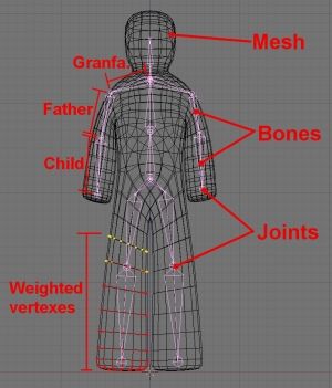
骨骼动画的实现思路是从我们人的身体的运动方式而来的(所以VR就是对现实世界的虚拟嘛 :-))。动画人物的身体(肉、皮肤)是一个网格(Mesh)模型,网格的内部是一个骨架结构。当人物的骨架运动时,身体就会跟着骨架一起运动。骨架是由一定数目的骨骼组成的层次结构,每一个骨骼的排列和连接关系对整个骨架的运动有很重要的影响。每一个骨骼数据都包含其自身的动画数据。和每个骨架相关联的是一个“蒙皮”(Skin)模型,它提供动画绘制所需要的几何模型(Vertex,Normal,etc)和纹理材质信息。每个顶点都有相应的权值(Weight),这些权值定义了骨骼的运动对有关顶点的影响因子。当把动画人物的姿势和全局运动信息作用到骨架上时,这个“蒙皮”模型就会跟随骨架一起运动。如下图所示:
所以关键是对骨架进行动画生成,生成的方法也是用关键帧。关键帧动画是对人物的网格(Mesh)模型采用关键帧生成动画;而骨骼动画则是对人物的骨架采用关键帧生成动画,然后再让网格(Mesh)模型跟随骨架运动。关键帧动画实现的2个关键点是:关键帧的选取和中间帧的插补。
关键帧的指定有2种基本的方法:前向动力学(FK)和逆向动力学(IK)。前向动力学用一组节点的角度来找到末端受动器的位置;而逆向动力学则是找到将末端受动器置于所要位置所需的一组节点角度。前向动力学的优点是:计算简单,运算速度快,缺点是:需指定每个关节的角度和位置,而由于骨架的各个节点之间有内在的关联性,直接指定各关节的值很容易产生不自然协调的动作;逆向动力学的优点是:只需指定主要关节点的位置,负担轻,缺点是:计算模型比较复杂,开发者需要机械运动和动力学、几何学以及向量数学等方面的相关知识。
中间帧的插值分2步:(1) 根据当前时间,通过插值计算出每个骨骼的旋转、平移等值,形成中间帧的骨架。插值算法一般采用四元数(Quternion)的球面线性插值(Spherical linear interpolation)SLERP,SLERP特别适合在两个方位之间进行插值,不会出现像对欧拉角插值那样出现万象锁的现象,而且这种插值能产生更平滑和连续的旋转,表达方式也很简洁;(2) 根据骨架的变化情况,插值计算出骨架的“蒙皮”模型的各个顶点的位置变化。对于某个特定骨骼,“蒙皮”模型的顶点变换矩阵=初始姿势的变换矩阵的逆×姿势变换后的矩阵。另外还要考虑顶点可能受多个骨骼运动的影响。这时我们对每个与当前顶点相关联的骨骼,将其运动姿势变换矩阵×当前顶点相对于该骨骼的偏移向量×该骨骼对当前顶点的影响因子(即权重Weight),对所有与当前顶点相关联的骨骼都这么处理,然后相加,就得到当前顶点的新位置。
由此看出,如何设置各关键帧的骨架的各节点的位置和骨骼的转向(也就是骨架的POSE)是其中的关键,有2种方法:一种是由动画师手工放置,这个对动画师的技术要求就比较高,要求动画师对现实生活中的人和动物等的动作有细心的观察。否则设置的骨架动作就会不自然、不协调;另外一种是基于运动捕捉(Motion Capture)的方法,就是在人的各个关节处安置运动捕捉传感器,当人做各种动作时,捕捉仪器就将各节点的位置数据记录下来,这样我们就可以根据这些节点数据进行骨架建模。由于这是捕捉的真实的人的动作,所以这种方式得到的动画就很自然、很真实,但捕捉仪器造价昂贵,国内估计只有很少几家有财力的游戏公司才购置了这些设备吧。
目前有好多3D模型格式支持Skeletal Animation,像Microsoft的.X格式、MilkShape的MS3D格式、Half Life的MDL格式、ID Software的MD5格式等。我准备首先研究一下MS3D格式,因为它有公开的格式说明文档,阅读起来比较容易,而且应用很广。当然,首先要深入学习Skeletal Animation的底层技术,打好坚实的基础,呵呵!
基于可编程图形处理器的骨骼动画算法及其比较
2009-10-19 作者: 季卓尔 张景峤 来源: 万方数据
关键字: 骨骼动画 可编程图形处理器 计算机图形 蒙皮网格 统一
引言
提高计算机动画的画面质量与渲染的效率和减少计算机动画所需占用的空问,已经成为计算机动画使用中比较重要的问题。计算机动画的画面质量与所占用的空间大小成正比,与渲染的效率成反比。越是精致的动画,占用的空间越大,渲染的速度越低。所以如何在保证画面质量的情况下减少动画所要占用的空间,并提高计算机动画的渲染效率成为一个值得研究的课题。较早出现的一种称为顶点动画的三维动画技术,根据时闯对两个关键帧的信息进行插值计算,以得到对应时间的动画数据。其优点是实现起来比较简单,所需的计算量也很少。但它同时也带来一些问题。比如,顶点动画需要占用大量的内存,插值计算时动画容易产生变形等。由于顶点动画的一些问题,一种新的方法被提出,即骨骼动画,它特别适合于人物和其它的脊椎动物的动画模拟。骨骼动画作为一种新的动画技术,它与许多技术进行了结合。比如在骨骼动画中融入了正向反向动力学,电影中常用的动作捕捉技术等“I。WuFu-ehe等嘲提出了一种创建骨骼的方法,称为范围连接图方法。这种方法保留了拓扑结构的信息,并且它不像中间轴变换方法那样对模型摆动比较敏感。尤其应用于复杂模型时得到的结果十分符合人的感觉,使动画显得更加的真实。骨骼动画的诞生对于游戏渲染引擎来说是一项莫大的进步,它在很大程度上提高了游戏中人物渲染的效率。渲染引擎包括了骨骼动画,粒子系统,LOD(1evelofdctial),光照系统,阴影等诸多组成部分。作为渲染引擎的一部分,对于如何提高骨骼动画的运行效率,应从整个系统的高度去考虑。
GPU(graphic process unit)作为游戏渲染的重要硬件之一,随着其处理能力的不断提升,和可编程性能的不断完善,如何让GPU代替CPU完成更多的工作已成为国际计算机图形处理及其相关领域的研究热点之一。吴恩华等人叫介绍了一些在GPU中实现辐射度、光线跟踪、碰撞检测、流体模拟方面的文章,并提出了一些关于使用GPU像素Shader进行代数运算的方法。沈潇“1等提出了一种基于可编程图形硬件的实时的阴影生成算法,改善了阴影渲染效果,并且防止了走样。Yang Xiao嗍等提出了一种基于GPU的实时处理阴影锥的方法,相对于过去在很大程度上提升了阴影生成的效率。Aaron旧等提出了一种基于GPU的数据结构库,使GPU编程者可以根据不同的算法使用不同的数据结构。Cbristophd”等提出了一种基于GPU的实时网格简化方法,将网格简化算法移植到GPU中,并提出了一种通用计算的数据结构,这种数据结构使用于流处理器架构。对于骨骼动画而言,将某些计算移植到GPU中去无疑对骨骼动画,乃至整个渲染引擎的效率而言都有很大的提升。Kipfe一"1等提出了一种基于GPU的实时大规模的粒子系统,并构建了一个通用的粒子系统的引擎,该引擎还实现了粒子之间的碰撞和可见性排序等功能。Shiue等人91提出了一种基于GPU的实时细分方法。他提出的实时GPU细分核心在不同细分深度生成细分网格,使得所有的计算工作都可由GPU的Shader来负责,由此细分算法的所有主要的特征能够得以实现。
1、基础知识
1.1骨骼动画
骨骼蒙皮动画也叫做骨骼动画。使用骨骼动画技术。可以塑造出各种各样,栩栩如生的动画角色。其中,人体的骨骼动画运用得最为广泛。一般来说,骨骼动画由两部分来表示。一部分是形成层次的一系列的骨骼,通常称为骨架,另一部分是蒙在骨架上的皮肤。
骨骼结构是一系列相连接的骨头,它们组成一个层次叫骨层级。其中一个骨头称为根骨,它是整个骨骼结构的关键,整个骨架都是由它发展而来。其它的骨头都附属于根骨,要么是它的子骨要么是它的兄弟骨。由此组成如图1所示的骨骼结构。在检索骨架的时候,一般先找到形成骨架的根骨,然后,由根骨开始进行检索,直到找到所需要的骨骼。
在骨骼动画中仅仅建立骨架是不够的。为了使骨骼可以动起来,一般通过对骨骼进行变换达到使模型动起来的效果。在对骨骼做完变换之后还需要更新整个骨架,以此来产生一个新的动作。骨骼的更新需要遵守一些规则。图2展示了骨骼更新所需要遵守的规则。
在图2中,整个骨骼的更新从根骨开始,直至所有的骨骼都更新完毕。每一个骨骼的变换都会影响到其兄弟骨骼和子骨骼。这种影响在一定的范围内会一直传递下去。
骨骼和骨架只是个概念结构,用于控制模型的动作,它与模型网格相关联。通过骨骼来控制网格,从而让模型动起来。这里的模型网格就是所谓的蒙皮网格。
在蒙皮网格中,所有网格点均与骨骼相关联。因此,只要对骨骼进行变换,再对与骨骼相关联的网格点做相应变换后,就可以使模型动起来。
在骨骼动画中每个顶点都与骨骼相关联,骨骼的运动会带动附于其上的顶点。骨骼对顶点的影响力的大小由每个骨骼的权重系数决定,对某个顶点产生影响的骨骼的权重总和为l。
使用骨骼动画可以节省许多内存空间,且能够较好的控制模型网格的变换。但是,骨骼动画的这些好处也是要付出一些代价的,与较少的内存消耗对应的是更大的计算量。由于现代CPU的超强运算能力以及GPU通用计算的发展,这似乎不是一个大问题。甚至可以把一部分计算转移到GPU上去,以节省更多的CPU计算能力给其它的部分的计算。
1.2可编程Shader技术
在过去GPU中的Shader分为两类,即顶点Shader(Vertex Shader)和像素Shader(PixelShader)。这两类Shader分别位于渲染管线的不同阶段,分别处理顶点和像素的数据。两类Shader只能各自处理各自的数据,即便Shader空闲也不能用于另一方数据的处理。
当今最先进的GPU已经不再区分顶点Shader和像素Shader。nVidia将二者合并由流处理器来代替,形成了统一渲染架构,使得所有的处理都在流处理器中统一进行。这样在GPU中处理数据的时候所有的处理单元都会被使用到,不会出现Shader空闲的问题,极大的提升GPU的处理效率。本文的算法正是基于此种架构设计的。在统一渲染架构中,顶点Shader和像素Shader拥有了相同的处理能力。所以过去许多因为像素Shader处理能力强而在像素处理阶段实现的算法,
可以根据需要转移到顶点处理阶段来进行。虽然在统一渲染架构中合并了两类Shader,但是渲染管线中的顶点处理阶段和像素处理阶段仍然存在。除了原先的顶点和像素处理阶段,在新的GPU架构中还增加了几何Shader(GeometryShader)。新的处理管线如图3所示。
2、基于可编程GPU的骨骼动画
在骨骼动画中涉及到大量有关于顶点的计算,如果将所有的这些计算都放在CPU中进行,那么CPU与GPU将处于一种利用率不平衡的状态。当系统总负载越来越大时,CPU就成为提高系统效率的瓶颈,减轻CPU的负担成为一种必然的选择。由此,可以将一部分与顶点相关的计算放入到可编程的GPU中进行。下面将给出本文所设计的3种在GPU中实现骨骼动画的方法。
2.1骨骼动画中主要数据计算的分析
由于CPU与GPU构造的不同,决定了他们计算与数据存储方式的不同。所以,基于CPU的算法并不能够简单的复制用于GPU中,必须先要对其进行分析与简化。骨骼动画中的数据计算主要包括以下4方面,骨骼与顶点的对应关系,骨骼的偏移矩阵与骨架的对应关系,骨架的更新,顶点的更新。
使用GPU迸行计算与使用CPU进行计算有很大的不同。GPU在顶点处理阶段处理的每一个点,都使用同样的算法进行计算,对于像素处理阶段的每一个像素也是如此。并且在GPU中每个顶点或者像素的计算是相互独立的。当前的计算结果不能用于下~个顶点或者像素。而且顶点与顶点之间,像素与像素之间,计算结果不能被共享。由此可见,GPU较适合处理逻辑比较简单的任务。所以在设计基于GPU的算法时应尽量保证程序的简洁。
在了解了GPU的计算特性之后,下面将对这4种计算分别进行分析:
·骨骼与顶点的对应关系:骨骼与顶点的创建是分开的,但在创建的过程中,我们要将骨骼与顶点绑定在一起。这样当我们改变骨骼时,顶点才会跟着一起移动。
·骨骼的偏移矩阵与骨架的对应关系:骨骼的偏移矩阵规定了绑定在某个骨骼中顶点的偏移量,它与骨架一起控制了顶点在空问中的位置。
·骨架的更新:骨骼矩阵的改变会对它的兄弟骨骼和子骨骼产生影响,所以要对相应的骨骼进行更新,即骨架的更新。
·顶点的更新:在整个骨架的位置改变后,附着在骨架七的顶点当然也需要改变,这样才能使模型动起来。被改变的顶点信息有顶点的位置及顶点的法向量。
从以上分析可以发现:骨骼与项点的对应关系需要保留计算结果以用于下一步的计算,并且由于涉及到很多的查找计算,所以算法相对比较复杂。骨骼的偏移矩阵与骨架的对应关系同样需要保留计算结果用于下一步的计算,同样因为涉及到很多的查找计算,所以算法也相对比较复杂。骨架更新的计算结果也需要保留并且由于骨架采样是树形存储结构,一股使用递归的方法进行更新。算法比较复杂,也并不适合在GPU中计算。但是,因为骨骼动画是许多不同骨架的演化结果.所以仍有办法在GPU中生成新的骨架。顶点更新的结果可以直接输出到屏幕上而无需保留,所以顶点更新是骨骼动画中最适合GPU计算的一部分。
2.2 CPU与GPU之间的数据传递
在过去的骨骼动画中,所有的计算都在CPU中进行,计算得到的所有结果都放到顶点缓存中,然后送入GPU,最后绘制在屏幕}二。由于本文的方法将顶点更新甚至骨架更新的一部分计算放到GPU中去处理,因此不仅要将原始的顶点数据送入GPU中,而且还要将所有用于顶点更新的数据信息一同传给GPU。
由于CPU与GPU之间进行数据传递并不像CPU从内存中调用数据那样方便,二者之间的数据传递相对来说是比较费时的,特别是在传递大段数据的时候更是如此。所以在算法设计中应尽量减少两者之间数据传递的频率,并且传递的数据量不要太大。CPU与GPU之阆数据的传递方法有两种:①直接传递,该方法在传递数据时消耗比较大。传递后的数据放在GPU的内存中,在GPU计算过程中调用比较方便;②利用数据纹理进行传递,该方法在数据传递时消耗比较小。但传递后的数据存放在GPU的纹理内存中,为了获取所需的数据,我们需要计算出数据在纹理中的位置,并对相应位置的纹理进行采样。
2.3几种基于可编程GPU的计算方法
2.3.1 CPU更新骨骼,GPU更新顶点信息
本方法将逻辑较为复杂的骨架更新等工作放在CPU中进行计算,将逻辑较为简单的顶点更新放在GPU中进行计算,充分利用了CPU与GPU的资源。但是由于骨骼更新的工作在CPU中进行,所以在每次渲染的时候都需要将更新后的矩阵传入GPU中去。如图4所示,首先在CPU中对骨骼与顶点的对应关系,骨骼的偏移矩阵与骨架的对应关系进行了计算,对骨骼矩阵进行了计算更新。然后将更新后的矩阵和顶点信息传入GPU中。最后在GPU中利用传入的骨骼矩阵对顶点信息进行更新。
2.3.2 GPU更新骨骼与顶点信息
本方法是顶点动画与骨骼动画的结合,用一组起始位置的骨骼矩阵和一组结束位置的骨骼矩阵来表示一段动画,即对始末位置骨骼矩阵进行线性插值得到中间动画姿势。本方法在初始化的时候完成起始位置骨骼矩阵和结束位置骨骼矩阵的计算工作,然后将所有与骨骼动画相关的计算都放入GPU中完成。本方法的优点在于减少了CPU与GPU之间的通讯,缺点在于仅使用GPU进行计算,浪费了CPU的资源,加重了GPU的负担。如图5所示,首先在设备创建的过程中对骨骼与顶点的对应关系,骨骼的偏移矩阵与骨架的对应关系,起始骨骼矩阵和结束骨骼矩阵进行了计算。然后将计算好的矩阵传入GPU中去。最后在GPU中对起始骨骼矩阵和结束骨骼矩阵进行插值运算,得到当前时间点的骨骼矩阵并利用该矩阵对顶点信息进行更新。
2.3.3预创建骨骼动画方法
本方法以数据纹理作为传输方法,通过将骨骼动画创建到纹理中,再通过纹理采样的方式来获取骨骼矩阵。本方法的优点在于减少了CPU与GPU之间的通讯,缺点在于仅使用GPU进行计算,浪费了CPU的资源,加重了GPU的负担。但是数据纹理作为一种能方便传输大量数据的方法,为实现骨骼动画提供了另一种途径。
预创建骨骼动画法可以将骨骼动画数据制作成纹理,也可以创建一个纹理的ResourceView将数据映射到纹理中去。前者需要事先创建好纹理,而后者需要在初始化的过程中,计算骨骼动画的信息并映射到纹理的ResourceView中。如图6所示,首先需要创建一个纹理或者一个ResourceView,然后将该资源传到GPU中去,然后对传递到GPU中的纹理进行采样能够得到骨骼矩阵,最后利用骨骼矩阵对顶点信息进行更新。
3、实验结果
实验1是在P43.0的计算机上进行测试的,使用的显卡是ATI R300,内存512M。表1描述的是骨骼动画的程序不使用可编程GPU与使用可编程GPU时每秒所绘制帧数的对比。
由表1可以看到,使用了GPU之后,绘制的效率相对于不使用GPU有了很大的提升。而且在某一个范围之内,绘制的人物数量越是多,得到的性能提升越是大。所以当计算量越大时,CPU越会成为提升计算效率的瓶颈,使用Shade越能够使性能得到提升。但是这种提升也不是无限制的,从上表的统计结果可以发现,当绘制的任务数超过某个量的时候,效率就不再提高了。这是因为此时GPU的性能已被用尽,效率的提升已达到极限。如果想要再提高效率,则只有使用更高性能的显卡。
以上分析表明,使用GPU可以大大提高计算机系统计算的整体效率,并且这种提升在不超过一定极限的情况下,会随着计算量的变大而变大。
实验2的硬件环境是Intel PentiumD925处理器,King StoneDDRII 6672G内存,nVidia8800GTS显卡。使用的软件环境是WindowsVISTA。使用的开发环境是MicrosoftVisualStudi02005,DirectX 10,DircctX SDK April 2007。使用的模型源自微软,有4000多个顶点与6 000多个三角面片。表2为在CPU利用率较低的情况下,各种基于GPU骨骼动画的运行效率,并以静止网格(即只是显示静态模型,但并不对其进行骨骼变换)的渲染为参照。表3为在CPU利用率较高的情况下,各种基于GPU骨骼动画的运行效率,并以静止网格的渲染为参照。
表2的数据可以分为3个阶段来分析:①在渲染的模型数量较少时,由于GPU的运算能力比较强,所以GPU更新骨骼和预创建骨骼动画的方法相对于CPU更新骨骼的方法而言效率高一些。②当渲染模型的数量增加了一部分后,由于闲置的CPU帮助CPU更新骨骼方法分担GPU的一部分计算量,充分利用了CPU与GPU的资源,使得CPU更新骨骼方法获得了更高的效率。③当渲染模型的数量急剧增加后,由于CPU与GPU的负担均加重,闲置CPU分担GPU计算量的能力下降,GPU的计算能力也被大大消耗,所以出现了CPU更新骨骼方法与预创建骨骼动画方法效率相等的情况。
从表3的数据中可以发现,当CPU高负载运行时.GPU更新骨骼和预创建骨骼动画方法的效果要比使用CPU更新骨骼动画的方法要好。
综合以r.的数据可以发现,使用了GPU之后骨骼动画的效率有显著提高的。但骨骼动画效率的高低还取决于它所处的环境。只有最大限度的利用整个系统的资源才能得到最高的效率。
4、结束语
本文主要讨论了几种基于可编程GPU技术的骨骼动画口通过使用不同的可编程GPU技术,将骨骼动画不同部分的计算任务放到GPU中进行,使部分或者全部的计算量从CPU转移到GPU,从而将CPU从繁重的顶点变换,甚至骨骼更新的计算中解脱出来。本文在肯定了基于GPU的骨骼动画效率提升的同时,对不同的骨骼动画方法进行了分析,并指出骨骼动画效率的提升取决于其所处的环境。骨骼动画的价值体现在其所处的系统,比如游戏引擎。作为游戏引擎的一部分,骨骼动画方法的选择应该从引擎效率最大化的角度去考虑。单独考虑提升骨骼动画效率的意义并不是很大。
随着GPU的不断发展,越来越多与图形相关的算法可以移植到GPU中去。不仅骨骼动画,同样。光照系统,粒子系统,LOD*阴影,模型简化都可以从GPU中受益良多。事实上很多与图形相关的算法都用到了GPU技术,不过在渲染管线不断改进与完善的今天,更多基于GPU的算法可以被提出。
骨骼动画导论
先说明,这篇文章由我翻译自Evan Pipho的<理解骨骼动画
骨骼动画是使用”骨头”来运动一个模型而不是通过手动编辑和移动每个顶点或面而实现的动画.每个顶点被附着到一根骨头(或有时是多根骨头).一根骨头或一个关节只是一组顶点的一个控制点.这些概念类似于我们身体里的关节,例如我们的膝关节或腕关节等.当骨头运动时,每个附着在它上的顶点也跟着运动,如图5.2显示的那样.甚至骨头自身的运动也会导致其它骨头的运动.这使得模型运动起来比较适当合理,因为在真实的生活中,身体的一部分运动会影响到身体的其它部分.所以,程序员需要能利用骨头来计算单个顶点的变换.虽然这会带来较多的工作量,可是结果证明这是值得的.
图5.2 顶点动画需要你移动每个顶点,而骨骼动画使你只需移动模型中的一根骨头,顶点将能随之而变.
骨骼动画的优点
骨格动画比传统的顶点变换型动画有很多优点,正如你在前面章节里看到的那样.
首先,也是对于玩家最直观的一点便是要增加真实感.基于骨骼运动的角色更趋于真实性,并常出现在比传统模型要求和周围事物有更强交互性的地方.要使模型更趋于运动真实性,则对基于骨骼的模型来说确是件简单的事.在传统的关键帧动画中,游戏会在两个位置中间进行线性插值.然而,在这种情况下,关节实际上并没有旋转,这对于生命体以旋转方式运动会有问题.
这对用户而言,并不那么明显,但对程序员来说,那样的动画是否占用了较少的存储空间是非常重要的.用于代替为每帧动画都存储一组新的顶点,所有我们需要存储的只是骨头的旋转和平移信息.这可以节省巨大的存储空间,你仅仅只要加入骨头和顶点—骨头附着信息.
这因骨骼动画需要而多加的一点存储空间可以用于保存更细致的模型,加入额外的支运动帧,或甚至可经适当改进后,用于游戏的其它地方.你能够添加更多细节至游戏的世界中,改进A.I.来提供一个更刺激的游戏,或者加入一些很酷的东东或复活节彩蛋,而这些都是原来你很想加入却因涉及空间问题而不能加入的.
而另一个优点表现在那些创建游戏3D内容的美工上.一个好的骨骼动画系统将缩减美工做模型动画的时间.几乎每一个好的动画程序都已使用骨骼动画来确保模型运动的过程从美工到程序员,再到游戏,最后到玩家的平滑过渡.这加速了游戏内容的创建过程,也确保了当模型被导出成游戏所使用的格式时没有动画或特征的失真.
一个更长远的优点是对程序员的另一个好处(这越来越好了,不是吗?).因为骨骼的自由性,这使得你可以随心所欲地实时定位它们,也可以实现在运行时创建动画.就相当于提供了一个更多样化的动画库.你甚至能够让游戏控制当身体碰到一个物体时的动作,或从一个斜坡上滑下来.这种技术是在玩的时候即时产生的,Unreal Tournament 2003’s Physics系统(http://www.epicgames.com)里就有这样一个值得注意的例子.角色和模型在环境里面真实交互,包括从斜坡上滑下和靠在上面徐徐移动.
骨骼动画有一个缺点就是相对于传统的关键帧动画,它不容易被理解和实现.本章将帮助你缓解任何你对骨骼动画的担心.
骨骼动画的原理
首先来看看你的手臂.将你的手臂在你胸前展开并观察它.你的手臂有许多骨头,两根主要的大骨头(two main ones),还有手掌(译注:这里指腕关节到指尖的所有部分,下面说的手掌也一样)和手指上的一些骨头.
移动你的手指,是不是它们移动?只移动你的手指,而你手臂上的其它部分并不会因此而移动.现在弯曲你的肘关节,不仅你的手臂移动了,而且你的手指和手掌也同样跟着移动了.如果不是这样的,那你的手臂和你的手掌及手指就变得断开了,且每部分都孤立得悬挂在空中,这可不太好.
如何将这个手臂和骨骼动画关联在一起运动呢?你的手臂代表了3D模型的一部分,你的手指,手掌,以及手臂的上下各部分都是这个模型的一部分.不同的关节和骨头贯穿了你的手臂,如肩关节,肘关节,腕关节,还有指关节.
这就是说,当你移动手臂”上游”的一根骨头时,任何在这根骨头的下游部分也都会跟着移动.这就是骨骼动画最基本的概念.
这样就有一个美妙之处是:它可以允许你移动模型上的任何一根骨头,并渗透到下面的移动,应用到以这个移动为原点的下面的任何事物. 例如,这允许你只需移动角色的肩膀,不需担心肘和手的移动位置,因为它们会自动移到正确位置.你也能够通过复位以确保它们会被自动更新.图5.3显示了一个关节和附着在这些关节上的顶点的例子.
图5.3 当执行骨骼动画时,你不必担心关节,或骨头之间的结合点.每个顶点实际上是附着(关联)到关节点的,而不是骨头.
根关节
根关节是一个模型中的终端关节.任何其它关节都以自己的路径最终关联到根关节.任何对根关节的操作,如不论是平移或是旋转,都会影响到模型中的每个顶点.你可以认为根关节是控制所有其它关节的关节.简单修改根关节,你能使角色直立行走,或旋转他以让他倒过来在天花板上行走—所做的只是一个简单的调用.
在每个模型里只有一个根关节,它没有父关节.根关节通常是许多骨头连接的地方,而不是需要一个小动画的地方.例如包括中部和下后部,但没有明确要求根关节一定要在模型中的某个准确位置.只要你愿意,每个模型都可以不同.图5.4显示了当根节点的位置和朝向被修改后会发生的变化.
图5.4 旋转或平移根关节将影响模型中其他所有的关节和项点.
骨骼动画导论(二)
由于希赛博客日志容量限制,只好拆成两篇发表
先说明,这篇文章由我翻译自Evan Pipho的<>一书的内关于骨骼动画第五章的内容,去掉了前面的说明和最后的Demo说明,包含了所有的理论内容,转载请注明出处,谢谢!
父关节和子关节
一个关节可以有父关节和子关节.其父关节会影响到它做任何事情.父关节的旋转和平移会影响计算当前关节的新位置.再拿手臂的例子来说,肘关节是手掌的父关节.移动肘则影响手掌.在简单的骨骼动画里,每个关节只有一个父关节,如果有的话.
但是,一个关节可以有许多子关节.子关节是相对于父关节来说的.任何你对父关节做的事都会渗透到子关节.换个角度来说就是,当前关节是所有在它下面的关节的父关节.
图5.5 父-子关节的关系
骨骼动画的关键帧
常规关键帧动画保存了多份顶点拷贝,骨骼动画系统也有关键帧.关键帧的再现是一个模型位置的瞬时状态.
然而,不同于每个关键帧都包含其自身所有顶点的拷贝的方式,骨骼动画的关键帧或叫骨骼帧(boneframe)包含了旋转和平移的变换信息,一般平移是一个X,Y,Z值的形式,和三个分别包含了按X,Y,Z轴旋转的值.正如常规顶点关键帧一样,这些骨骼帧必须被插值来提供平滑的动画效果.
位置或平移的值可以在两个之间进行线性插值,就像你在传统关键帧动画里对顶点的操作一样.但旋转则有问题,简单的在两个值之间进行平移那样的插值会产生奇怪的效果.旋转将不是平滑的,它可能会加速和减速,这依赖于其自身的位置.如果两个旋转信息之间的差异比较大,模型可能像胶在一起的方块那样出现”渗出(ooze)”.这是因为使用线性插值,所有的东西都是沿着直线插值的,如果这用这种方式执行旋转就会产生奇怪的效果,因为旋转是沿着弧插值而不是直线.对弧形路径按两端点的直线方式而不是沿弧的路径方式就会产行”渗出”效果.
解决这个问题的最好方法就是采用四元数.这你在第二章就学会过了.”介绍四元数”,四元数最大的优点之一是他们可以容易地进行插值.不仅容易插值,而且能很容易地进行球面线性插值.
球面线性插值在球面上的两点之前进行插值.然而,相对于在两点之间以直线方式逼近,球面线性插值是沿着球表面的曲面的.你可以设想捡起一只球,比如一个篮球,并在上面标上两点,然后,用你的手指找出这两点间最短的路径.因为你的手指不能进入球的内部,于是这条在两点间的路径将是一条弧.这就是SLERP的处理方式.使用SLERP函数,旋转就可以沿着弧进行插值,创建出一个比较平滑的,顺眼的效果.
计算位置
利用你在上面己经阅读到的信息,你可能想尝试实现骨骼动画了.然而,你还没有学习关于父关节是如何影响子关节的具体内容.简单地使用关键帧将使每个关节独立地移动,很可能产生一个奇怪的,扭曲的网格.
这部分内容将告诉你关于如何更改它以使关节之间能正常运动.首先你要做的就是创建一个变换矩阵,该矩阵用于每一个使用了不同旋转和平移关键帧数据的(关键帧)点.这个变换矩阵可以通过先生成三个旋转矩阵(译注:x,y,z三个方向的旋转矩阵)和平移矩阵,这在第一章已经学过了, 再将这三个矩阵相乘就会生成了最终的变换矩阵.你也可以使用matrix类的SetRotation和SetTranslation函数来避免你自己做矩阵乘法.这个生成的矩阵叫做相对矩阵(relative matrix).
下一步你需要计算出一个绝对矩阵(absolute matrix).绝对矩阵是关节的相对矩阵乘上它的父关节的绝对矩阵得到的.绝对矩阵告诉你关节的绝对变换(译注:就是将关节的本地坐标变换为世界坐标).这包括了自身的相对变换,除此之外,层次结构中所有在它之前的关节的变换都已计算完成.这允许其他关节的移动作为移动关节链上游关节的结果.细想一下,例如,当你移动肩膀时肘又是怎么移动的,这引出了一个问题:你如何计算最初的绝对矩阵?记住,根关节是没有父关节的,因此,它的绝对矩阵就是它的相对矩阵.
假如你以正确的顺序遍历了各关节,同时按此顺序计算出各个绝对矩阵,每个关节(的绝对矩阵)将会包含它父关节的变换,以及它父关节的父关节的变换等等.图5.6显示了当你变换一个关节前顾及所有先前(关节)的变换时发生的情况.
图5.6 遍历各关节,并顾及其所有前面的变换.注意哪怕只有一个关节要移动,在它下面的关节也得跟着移动,这很像移动你的臀部,则你的膝和踝也得跟着移动一样.
你是否只存储了子关节的索引,而没有储存关节的父关节索引?你立即要访问的索引集依赖于模型的格式.一些格式像MS3D同时给你每个关节的父关节索引,其它格式则可能给你子关节索引.使用子关节索引需要一个明显不同于使用父索引的方法,但一点都不会比后者难.你再次从根关节开始,在计算了根关节的变换矩阵之后,通过一个类似于glPushMatrix的命令将一个新的矩阵压入栈内.就创建了一个新的世界变换矩阵(world matrix)的拷贝,这个世界变换矩阵是在被显示前执行了所有的几何变换的矩阵.现在用你的新矩阵乘以根关节的本地矩阵.结果就是世界变换矩阵,它在下一个骨头被画出之前将所有事物放置到正确位置,父关节的变换也被考虑在内了.举个例子,角色的臀部的旋转可能是某些动作的总合.因为膝关节和踝关节是臀关节的子关节,它们也要被旋转.
绘制函数像这样递归,它对自己的子关节继续调用绘制函数,每个子关节又对自己的子关节调用渲染函数,以此类推直到到达终端关节(没有子关节的关节),复位栈用一个glPopMatrix这样的命令.例如,当要绘制一个角色的一条腿时,新的矩阵被压入栈内用于计算膝关节,踝关节和脚关节.但是,如果要开始计算手臂时,你应该出格到处理腿之前的栈状态,否则,每当你移动腿时,手臂也将跟着移动了.
图5.7显示了一个递归渲染函数.
图5.7 渲染用子索引代替父索引存储的关节
将网格附着到骨骼
当你的关节己能平滑运动的时候,也是该将网格附着到骨骼的时候.网格(mesh)组成了模型的形状,它是由一组使模型具有立体感和细节的顶点和三角形组成,没有网格,基于骨骼运动的模型只是一个简单的骨架.每个网格的顶点存储了一个指向关节数组的索引,用于指示它被附着到某根骨头.现在,存储关节的方式决定了这些顶点的变换和渲染的方法.
如果每个关节存储时带有其父关节的索引,同时你已经遍历和计算了最终的绝对矩阵,那么附着网格是很简单的.确保变换后的顶点保存到一个专门的地方,不要覆盖原始的顶点.这是因为在绝大多数格式里,骨骼帧不会被累积,每帧保存了从起点起的特定关节的旋转和平移的信息.如果你不回退到原始顶点,那么当每次计算新顶点位置时,模型将会飘乎不定得运动.图5.8中可以看出每个顶点单独附着到一个关节是什么意思.
图5.8顶点附着到关节
现在你很可能在对自己说,”好的,我能运动一个模型的顶点,那三角形,法线,以及纹理坐标怎么处理呢”? 这也正是骨骼模型真正开始闪光的地方.每个模型包含了一个纹理坐标的集合和一个三角形信息的集合.仅因为顶点的位置变更并不意味着三角形顶点索引和纹理坐标也会变化.这意思是说,当你第一次设置好它们之后就根本不需要再担心它们.
法线则是另一回事了,因为多边形的朝向和顶点的位置更改了,因此法线也相应更改了.如果你正在使用面法线,那么你在每一帧将他们传给渲染器之前都需要重新计算.然而,如果你一开始就计算了顶点法线,那么你很幸运,顶点法线不必在变换后都完全重新计算,它们能利用和顶点相同的变换矩阵来进行变换.唯一不同的是,你不需要考虑平移.使用matrix类的Transform3()函数将旋转你的顶点法向量,同时仍能保留其原始大小.
如果关节保存了子关节的索引,并且你使用glPushMatrix将当前的变换矩阵压入栈内,那么渲染模型就会变得十分容易.对这种情况,没有必要在显示之前变换每个顶点.不管渲染任何东西都没有更改的必要.任何你要渲染的现在将被适当变换,甚至面法线.另一个需要考虑的问题是,顶点如何附着到多于一根的骨头.此时,每根骨头将被赋予一个权重,这个权重决定它影响关节点的比重.最终的变换是所有这些被附着的骨头的变换的加权平均.
11.4.2 骨骼动画公式
本节你将回顾一些骨骼动画用到的概念和数学公式。一个骨骼动画是由许多关键帧组成的,每个关键帧存储了一个bone的配置(朝向和位置)和bone对应的时间。在每个时间间隔,你使用一个或多个关键帧改变bone的配置。
图11-7展示了一张如图11-3中的骨骼的动画,当Left Shoulder bone的朝向变动时也会影响到其他bone。
图11-7 图11-3中骨骼的Left Shoulder bone动画
注意所有的后代(descendant)bone的配置都改变了。
要实现如图11-7的结果,只需对Left Shoulder bone存储一个关键帧动画。虽然所有的 Left Shoulder children的配置都改变了,它们与Left Shoulder的关系还是不变的。换句话说,你不需要存储Left Shoulder children的新配置,因为你是基于新Left Shoulder配置计算children的配置的。这样,当你需要更新模型时,你需要计算每个bone的绝对配置,然后使用这些bone变换顶点。接下来我们会学习一些变换顶点用到的公式,你将使用这些公式更新并绘制模型。为了更好的利用GPU,你将在动画模型effect中实现这些公式。
变换顶点
模型的每个顶点包含了哪个bone影响它的位置和bone作用在顶点上的影响的信息。你可以计算顶点的最后位置,而这个位置只被一个bone影响,下面是公式:
PF=P0′[Bone•W]
在这个公式中,PF是顶点的最后位置,P0′是顶点的初始位置,Bone是包含影响顶点的bone的绝对配置的矩阵,W是影响的权重。因为顶点只被一个bone影响,所以这个权重是1(即100%)。这个公式显示了如何计算顶点的最后位置:用包含bone的绝对配置的矩阵变换顶点的初始位置。
顶点的初始位置必须和bone使用相同的坐标系统,这个坐标包含在bind pose中。当顶点连接到bone时,所有的bone是在bind pose位置中找到的,而且所有的bone动画是应用到骨骼的初始bind pose的。你可以通过将顶点位置乘以反bone矩阵将顶点的初始位置转换到bone的bind pose坐标系统中,由以下公式决定:
P0′=P0[Bone-1BindPose]
在这个公式中,P0′是顶点在bind pose坐标中的初始位置,P0是顶点在模型空间中的初始位置,而Bone-1BindPose是bone绝对配置的反矩阵。要将顶点坐标转换到bone坐标系统,你只需将顶点坐标乘以bone的反矩阵。使用这两个公式,你可以让所有的顶点都动起来。
组合bone变换
第一个公式不允许一个以上的bone影响一个顶点,但在很多情况中往往是几个bone共同影响一个顶点。要计算几个bone共同影响一个顶点的最终位置,你需要计算施加影响的每个bone的顶点位置。然后你就能通过对顶点最终位置求和计算最终位置。下面的公式表示有几个bone共同影响一个顶点的计算公式:
注意用来变换顶点的权重的和必须是1。最后,下面的公式表示变换顶点的完整方程:
注意在前面的方程中你首先计算矩阵的和,然后一次性的变换顶点。
http://www.okino.com/conv/skinning.htm

Since early 2001 Okino has pursued active R&D in the area of skeleton and skinning conversion between the most popular 3D character animation software packages or destination file formats, those being Autodesk Maya, Autodesk 3ds max, Newtek Lightwave, Autodesk Softimage, DirectX, Collada, FBX, U3D and Milkshape-3D. This WEB page will provide a good overview of the concepts behind skeletons and skinning, and why in general conversion of skinning data between these aforementioned software packages is ripe with potential problems.
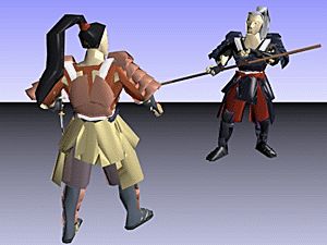

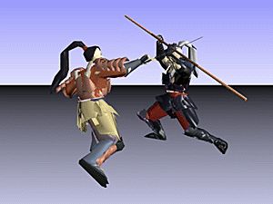

FBX 'Samurai' skinned mesh (with skeleton) model imported, animated & rendered in Okino's NuGraf. Model courtesy of Kaydara/Alias/Autodesk.
Click on any image to view a Windows Media 640x480 animation (2.3MB download).
Based on our direct customer experience, our long and focused development, and on the feedback we have provided the animation companies to help correct bugs and problems in their mesh skinning code, we believe we have the best, most refined and most technically advanced skinning conversion systems presently on the market. This is especially true if you need to convert skeletons and skinned meshes between 3ds max (Character Studio or SkinMod), Lightwave and Maya; these three programs are particularly not compatible due to bone re-alignment differences, issues with Biped off-axis scaling and 'missing' bind poses from Maya. Our skinning system is also well known for being able to fix incorrectly converted skeletons & skinned mesh conversions created from other free and non-free programs: all you need to do is export to the Okino .bdf file format from 3DS MAX or Maya, then re-import the file again - the Okino "Arctic" toolkit will compensate for inherent problems in the conversion process. If you perceive any problems in our skinning conversion system, which rarely if ever occur, then just email us and we'll explain what you are seeing.
Since the concept of mesh skinning is rather straightforward we initially thought that skeleton and skinning data conversion would be a simple matter to develop, but several years after the fact we can say this is not always the case; all sorts of issues can crop up during conversion of such data (that other converters didn't seem to address), such as:
- Propagating "skewing" or "off axis" scaling data in a 3ds max hierarchy down it's skeleton tree before export (a classic problem with 3ds max hierarchies),
- Re-aligning Maya "joints" for use in 3ds max as "bones" by combining and then resampling the animation curves on the skeleton nodes (this unique Okino processing option in our 3ds max plug-ins can even be used to fix up bad conversions made by other converters),
- Converting between the less common method of having the skeleton beneath a mesh (as used by Lightwave) to the more typical method of skeletons and meshes being distinct from each other.
- Converting from implicit skin weight formulas (such as in Lightwave) to explicit skin weight values, as used by all related 3D file formats.
- Or even computing "sane" sizes & alignments of Maya joint-based skeletons going into 3ds max bone-based skeletons.
For DirectX, Okino has had the industry accepted .X standard exporter implementation since 1997. The .X file format did not change until DirectX 8.1 came along, which added support for real time mesh deformation via smooth skinning techniques, as well as vertex duplication lists. Okino has expanded both its .X importer and exporter to handle mesh skinning and vertex duplication lists, as well as being able to import the new "matrix animation" data representation. As we learned in the deep past, the simplest file formats cause the most trouble to develop, and this is directly applicable to the .X file converters; to allow for care free export of skinned meshes we added the ability to output the mesh data after the skeleton has been output (for cases where a mesh might be located inside a skeleton hierarchy) and automatic creation of extra dummy bones in cases where the vertex weights don't add up to 1.0 on a mesh (DirectX doesn't like that case).
Skeletons in a 3D character animation have a direct correlation to a human skeleton: they consist of articulated joints and bones, and they can be used as a controlling mechanism to deform attached mesh data via "skinning". The skeleton is actually just composed of "null nodes" in 3D space (or "dummy nodes" or "grouping nodes" as they are also often called). Parenting the null nodes together creates an explicit hierarchy, and the transformations on the null nodes define the rotation and offset of each null node from its parent null node. The location of each null node coincides with a "joint" and the distance between two child-parent null nodes defines the length of the bone.
Some 3D programs are "joint based" and others "bones based". Maya and Okino's PolyTrans are "joint based" which means that the bone is visualized implicitly between two joint nodes (two null nodes). Thus, you always need at least two joints to define a bone. Other programs, such as 3ds max and Lightwave, are "bone based" which means that a bone is visualized based on a starting location, direction and bone length (a child joint node is not necessary in these programs for a bone to become visible).
Inside Okino's stand-alone software (PolyTrans and NuGraf) skeletons are visualized as a sphere centered at each joint, with a trapezoidal bone connecting the spheres. This is exemplified in the following figure:
"Skinning" is a popular method of performing real time deformation of polygon meshes by way of associated bones/joints of an articulated skeleton. "Skinning" is the process of binding a skeleton to a single mesh object, and skinning deformation is the process of deforming the mesh as the skeleton is animated or moved. As the skeleton of bones is moved/animated, a matrix assocation with the vertices of the mesh causes them to deform in a weighted manner. Skinning is a popular method for doing deformations of characters and objects in many 3D games.
The figure below shows the basic components of skinning, that is the single skin mesh on the right side and the skeleton of bones on the left side. skinning2.gif Left: the Single Skin Mesh. Right: The Skeleton of Bones/Joints. ``Rock'' model from the Autodesk Character Studio CD. Copyright (c) Autodesk.
Okino's PolyTrans/NuGraf software has a nice implementation of mesh deformation via weighted joints, or in other words "smooth skinning". It was created as a pipeline to import, retain, playback, query, optimize and re-export skinned data between the major character animation file formats and animation packages.
Skinning works on the principle of moving one or more "deformer" gizmos which in turn tug on specific vertices of a mesh object in a weighted manner to cause it to deform locally. It is common to have multiple deformer objects assigned to a single vertex, each with a share of the overall deforming "strength", but all which add up to a strength of 1.0.
The traditional character animation system uses a single skin mesh object (ie: an entire human body made from one mesh object) and an associated skeleton. The skeleton is defined simply as a hierarchy of NULL nodes; in some animation systems the skeleton's NULL nodes are visualized as bones (MAX, Lightwave) which have a source location and direciton, while in other animation systems they are visulized as connected joints+bones (Maya, Okino) which are simply spheres connecting one skeleton node center to the next skeleton node center. The skeleton acts as the deformer to the mesh object which is the deformee. This is illustrated in the figure below which is a skeleton on the left side deforming a single skin mesh in realtime on the rightside; as the bones are moved they deform the mesh object:

Skeleton Causing Deformation of a Single Skin MeshSkinning creation in an authoring package proceeds by selecting a bone/joint and assigning it as a deformer to one or more vertices of a mesh object. A weight value is associated with this vertex/bone assignment. A value of 0.0 means that no tugging will be done while a value of 1.0 will have the bone perform a full tugging on the vertex. In many cases there will be multiple bones associated with a single vertex (so that multiple parts of the skeleton manipulate localized areas of the mesh), in which case all of the weights associated with a single vertex must be "normalized" and add up to 1.0. Also, as an integral step, when the skeleton is first associated ("bound") with the mesh object a series of "bind pose" matrix snapshots are taken which define where the mesh object and where the skeleton joints were located in worldspace at the moment of binding; these "bind pose" matrices provide a sort of static, fixed coordinate system with which the skinning playback algorithm can detect if a skeleton has become animated/transformed, and thus can use the differentially computed changes in the skeleton positions to equally transform the vertices of the bound mesh object, which is the purest definition of "skinning".
As some terminology, if there is one bone per vertex, and the weight is 1.0 then this is "rigid" skinning, else if there are multiple bones per vertex and the weights are not equal to 1.0 then this is "smooth" skinning.
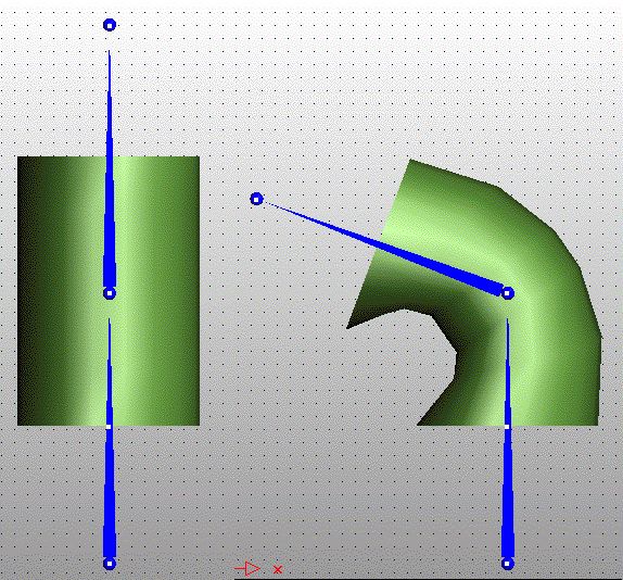
The following figure shows one of the simplest examples of skinning. Here we have a single cylindrical mesh object being deformed by two bones, the bottom one which is static and the top one which is animated. The top cap of the cylinder is only weighted to the top bone while the bottom cap is only weighted with the bottom bone so that the caps don't get skewed unnecessarily; however, the vertices between the top and bottom caps are weighted in different proportions between the top and bottom bone, so that their movement will come about partially from the rotation of the top bone and the static binding location of the bottom bone:

Cylinder Being Deformed by Two Bones
Skeleton Causing Deformation of a Single Skin MeshSkinning is the process of binding a skeleton hierarchy to a single mesh object. This is done by assigning one or more influencing joints (ie: bones) to each vertex of the mesh, each with an associated weighting value. The weight value defines how much a specific bone influences the vertex in the deformation process. NOTE: in general a mesh can be influenced by any other object in the scene as its deformer and not just NULL nodes tagged as skeleton joints; basically any instance, any NULL node instance or any instance tagged as a joint can be used to deform a mesh object (only the NULL node's transformation matrix is needed in the deformation process).
When the mesh is initially bound to the skeleton a "bind pose" world-space snapshot is taken of all transformation matrices of the mesh and skeleton nodes. These bind pose matrices allow any vertex position to be transformed into the local coordinate space of its associated influencing bone, at the time when the mesh and skeleton were in their original undeformed position (the "bind pose", "rest position" or "reference pose"). During realtime playback any movement of the skeleton away from its "bind pose" will cause the mesh to deform accordingly.
If a skeleton and mesh have been imported and bound together with skinning weights, then most probably the bind pose matrices have been defined and set as well. These matrices define the world-space location of the mesh object and its related skeleton bones/joints at the time of binding. Normally in the PolyTrans/NuGraf user interface you will see the mesh deformed under the influence of the skeleton's current pose (unless skinning is globally disabled). If you wish to revert the skeleton and mesh back to their poses at the time of initial binding, with no deformations applied, then you need to "Go to Bind Pose" on the mesh instance and every bone/joint instance. The final result will look like the following image (initial bind pose often has the arms stretched out and palms of the hands downward):
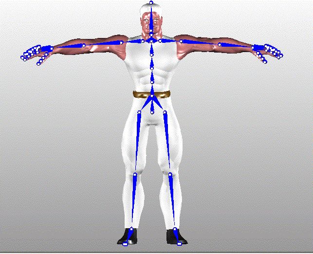
Model Forced into "Bind Pose"
The "bind pose" is often the most confusing aspect of learning to program the skinnig API yet the absolute most important concept to understand. The "bind pose" is the pose of the mesh object, the skeleton and their relative offsets at the moment the skeleton is bound to the mesh object and before any deformations begin to occur. This pose will often look like that shown in the figure above with the arms stretched out and level with the shoulders, and with the skeleton aligned with the limbs of the mesh object:
At this very moment, when the skeleton bones get bound to the mesh (via the bone/vertex assignments with corresponding weight values), a "snapshot" matrix called the "(Worldspace) Bind Pose Matrix" is taken for every bone/joint and the mesh itself (not to be confused with the local transformation matrix). These are very key and important matrices for skinning. The Bind Pose Matrices are stored in the instance definitions defining the mesh object and the skeleton bones/joints (bones/joints in the NuGraf toolkit are just NULL nodes, or empty instances as they are often called). The Bind Pose Matrices define the original world-space location of the mesh and bones/joints at the time of binding.
How are Bind Pose Matrices used during skinning deformation? This is the key point to comprehend: the matrices allow a raw vertex of the mesh (in local coordinates) to be transformed into world-space and then to each bone's local coordinate space, after which each bone's animation can be applied to the vertex in question (under the influence of the weighting value). The mesh's bind pose takes the vertex from local space to world-space, and then each bone's inverse bind pose takes the mesh vertex from world-space to the local space of that bone. Once in the bone's local space, the bone's current animated transformation matrix is used to transform (deform) the vertex's location. After all the bone influences have been taken into account, the vertex ends up in world-space in its final deformed location. In other words, these bind pose matrices relate the location of a vertex in its local mesh space to the same location of the vertex relative to each bones' local coordinate systems. Once this relation is known, via the bind pose matrices, it is easy to deform the mesh vertices by animating the bones.
All you need to keep in mind is that the mesh's Bind Pose Matrix takes its vertices into world-space, to the location at the time of binding, and each bones' Bind Pose Matrix takes the bones from local space to world-space at the time of binding.
http://topic.csdn.net/u/20080827/11/5825cbd2-e618-4f84-8504-0aa0064160a3.html
先说一下我对骨骼动画貌似很简单的原理的理解。下面的阐述也能看得出我对这些概念的把握其实很混乱,都是模模糊糊的。
骨骼像一棵树形结构那样,有父骨骼、子骨骼。每个骨骼保存的都是相对于父骨骼的转换矩阵,因此他们的世界矩阵都需要把自己的矩阵乘上父骨骼的世界矩阵才能得到(这是在d3d的情况。opengl的程序往往是反过来的,父骨骼的世界矩阵乘上本骨骼的矩阵,好像跟opengl使用矩阵的方式有关(压入堆栈))。Mesh的每一个顶点都可以受多根骨骼的影响,使用权重值来决定影响的程度。
在程序里面,可以先对一个顶点使用骨骼转换到正确的动作姿态(这时仍然只是在模型空间),再用该游戏物体的世界矩阵转换到游戏世界的正确位置上
现在先不考虑游戏物体的世界矩阵,只考虑模型空间。
这就有了一个问题:对顶点应当使用什么矩阵才能把它转换到正确的动作姿态上?想象一个简单的人物模型,裸模,身体各部位都是连贯的一个mesh。那么这些顶点都是在模型空间里定义的,而每个骨骼的那些缩放、旋转和位置信息都是在父骨骼的空间里定义的,这就不能拿骨骼的世界矩阵直接转换顶点。我认为,只有顶点是在骨骼的本地空间里定义的才可以使用骨骼的世界矩阵转换它。确实,有一个bind pose的概念,它其实就是矩阵,是骨骼初始的世界矩阵。矩阵是把坐标从空间A转换到空间B,那么这个矩阵的逆矩阵就能把坐标从空间B转换回空间A。所以bind pose矩阵的逆矩阵就应当能把模型空间的顶点转换到骨骼的本地空间去,然后在某一时刻,使用骨骼的世界矩阵转换这些在骨骼空间中的顶点,应该就能把它们转换到正确的动作姿态了。
在3DSMAX导出插件,使用IGame。如何得到各骨骼的bind pose呢?由于在游戏里,骨骼的空间信息仍然是相对于父骨骼定义的,所以这里求Bind pose,也是一样。而且一般bind pose取第0帧时即可。
使用IGameNode::GetWorldTM()函数(参数应该传0,也就相当于第0帧了),得到一个GMatrix结构,在调用GMatrix的ExtractMatrix3()函数就能得到一个Matrix3结构(它是以列为主的,跟d3d不一样)tm,这就是该IGameNode在第0帧时的世界矩阵了。本来tm应该就是该骨骼的bind pose矩阵的,但因为要保存相对于父骨骼的值,所以还要先使用同样方法得到父骨骼在第0帧时的世界矩阵ptm,让tm乘上ptm的逆矩阵。
接下来,实际保存的时候,由于我的Bone结构实际存储的是缩放、旋转、位置,所以要把这个tm矩阵拆开来。那么在游戏里要得到一个Bone的Bind pose矩阵,就是从这3个值构造一个矩阵,再乘上父骨骼的bind pose矩阵。这里,我发现我和Ogre引擎的一个非常显著的分歧。
我的做法,如上所述
Matrix IBone::GetBindPoseMatrix()
{
Matrix mtxScale = MtxScale(m_BindPoseScale); // m_BindPoseScale是一个三维向量,代表了bind pose的xyz方向上的缩放
Matrix mtxRot = MtxRotFromQuaternion(m_BindPoseRot); // m_BindPoseRot是一个Quaternion,MtxRotFromQuaternion函数可以根据一个Quaternion创建一个旋转矩阵
Matrix mtxTrans = MtxTranslation(m_BindPoseTrans);
m_BindPoseMatrix = mtxScale * mtxRot * mtxTrans; // 保存一下计算出的bind pose矩阵,如果愿意,使用一点技巧,可以使此函数不必每次都计算,这里省掉了
if(m_pParent)
{
m_BindPoseMatrix *= m_pParent->GetBindPoseMatrix();
}
return m_BindPoseMatrix;
}
可以看到,我先把本骨骼相对于父骨骼的bindpose缩放、旋转、平移合并为一个矩阵,再乘上父骨骼的bind pose矩阵,得到本骨骼的在世界空间的bind pose矩阵。
可是ogre,是先把本骨骼的bindpose缩放乘上父骨骼的bindpose缩放,本骨骼的bindpose旋转乘上父骨骼的bindpose旋转,本骨骼的bindpose位置加上父骨骼的bindpose位置,得出三个新的缩放、旋转、位置,再合并为一个矩阵。
这两种方法得出来的结果是不一样的。
这就是我的困惑。ogre的运行效果是没错的,我的运行效果是错误的,不过我之前用过ogre的方式,也不对。我想不对的原因不仅仅在bind pose矩阵的重新合并上,还在于动作的导出上。因为ogre的导出插件用的INode借口,没用IGame的IGameNode。
INode有GetNodeTM函数,文档上说能得到合并了父结点矩阵的矩阵,而IGameNode有三个函数:GetWorldTM、GetLocalTM、GetObjectTM,文档也没有说明哪个函数对应INode的GetNodeTM,我想当然的认为是GetWorldTM。
下面是我导出动作的做法。很羞愧,我其实不知道control、modifier到底是干什么的。
但是要导出骨骼的每一帧动作,似乎必须通过control。
首先IGameNode->GetIGameControl()得到一个IGameControl指针,然后调用IGameControl的GetFullSampledKeys函数就可以得到各帧的转换。这个函数也很让我困惑,我认为把参数Type设为IGAME_TM,就可以得到矩阵形式的转换,参数Relative,我不知道是相对于谁,相对于父骨骼?相对于前一帧?相对于第0帧?相对于bind pose?由于这个函数是计算各帧的转换,所以我倾向于认为是相对于前一帧的。那么我要的是绝对值,所以这个就设为false
IGameKeyTab selfKeys; // 在每一帧,本骨骼的世界转换
IGameKeyTab parentKeys; // 在每一帧,父骨骼的世界转换
IGameNode* pParent = pGameNode->GetNodeParent(); // pGameNode就是当前正在处理的骨骼, pParent是父骨骼
IGameControl* pControl = pGameNode->GetIGameControl();
pControl->GetFullSampledKeys(selfKeys, frameRate, TGAME_TM, false);
if(pParent)
{
pControl = pParent->GetIGameControl();
pControl->GetFullSampledKeys(parentKeys, frameRate, TGAME_TM, false);
}
for(uint k = startKeyFrame; k <= endKeyFrame; ++k)
{
Matrix3 tm = selfKeys[k].sampleKey.gval.ExtractMatrix3(); // 我觉得这就是本骨骼在这一帧的世界矩阵了,但别忘了最终要存储的是骨骼相对于父骨骼的转换信息(嗯,不一定是矩阵的形式,为了节约空间)
if(pParent)
{
Matrix3 ptm = parentKeys[k].sampleKey.gval.ExtractMatrix3(); // 同上,我认为这就是父骨骼在这一帧的世界矩阵了
tm = tm * Inverse(ptm); // 我认为把本骨骼在这一帧的世界矩阵乘上父骨骼在这一帧的世界矩阵的逆矩阵,就可以得到本骨骼在这一帧相对于父骨骼的矩阵了,这就是我要保存的
}
// 又一个困惑来了,要把矩阵拆成缩放、旋转、平移,要用到这个函数,可是这个函数返回的结构体中多出一个u来,虽然据说大多数时候无用
AffineParts ap;
affine_decom(tm, &ap); // 函数名称我可能记错了,因为这篇文章不是在编译器里写的
Point3 scale = ap.k; // 我认为这就是从矩阵里拆出来的缩放了,ap.u是什么?无视!
Quat rot = ap.q; // 这就是旋转
Point3 trans = ap.t; // 平移
// 下面保存本骨骼在这一帧的scale、rot、trans信息
}
下面进入游戏里
根据之前所述,使用bind pose的逆矩阵先把顶点转换到骨骼的本地空间,再使用骨骼的当前世界矩阵转换,就是能吧顶点转换到正确的动作姿态上了。
那么我的做法是:
IBone::GetMatrixForVertex()
{
Matrix mtxBindPose = GetBindPoseMatrix(); // 参见之前对此函数的叙述和代码
Matrix invMtx = mtxBindPose.Inverse();
Matrix ret = invMtx * GetWorldMatrix(); // 还有这个函数没说
return ret;
}
IBone::GetWorldMatrix() // 得到本骨骼当前的世界矩阵,其实实现原理跟GetBindPoseMatrix一样,也因此跟Ogre的方式截然不同
{
Matrix mtxScale = MtxScale(m_Scale);
Matrix mtxRot = MtxRotFromQuaternion(m_Rot);
Matrix mtxTrans = MtxTranslation(m_Pos);
m_WorldMatrix = mtxScale * mtxRot * mtxTrans;
if(m_pParent)
{
m_WorldMatrix *= m_pParent->GetWorldMatrix();
}
return m_WorldMatrix;
}
至此,我对骨骼动画的导出及渲染就是这样做的了,遗憾的是,运行结果是错误的。这两个多星期以来,我尝试修改了很多方式,都没有成功。也有参考Ogre的源代码,可是它坐标系不一样,它使用max sdk api而不是IGame,所以结果也不对。有谁能帮我看看是怎么回事?有谁曾经实现过,能指点一下吗?谢谢了。
