STM32学习(三)从点亮LED中总结配置GPIO的基本过程
基本过程如下
1.使用 GPIO_InitTypeDef 定义 GPIO 初始化结构体变量,以便下面用于存储 GPIO 配置。
1.1在"stm32f10x_gpio.h"文件中可以找到gpio初始化结构体
typedef struct
{
  uint16_t GPIO_Pin;             /*!< Specifies the GPIO pins to be configured.
                                      This parameter can be any value of @ref GPIO_pins_define */

  GPIOSpeed_TypeDef GPIO_Speed;  /*!< Specifies the speed for the selected pins.
                                      This parameter can be a value of @ref GPIOSpeed_TypeDef */

  GPIOMode_TypeDef GPIO_Mode;    /*!< Specifies the operating mode for the selected pins.
                                      This parameter can be a value of @ref GPIOMode_TypeDef */
}GPIO_InitTypeDef;
1.2“实例化”
GPIO_InitTypeDef GPIO_InitStruct;
利用上面初始化的对象来配置“Pin”、“Speed”、“Mode”参数
GPIO_InitStruct.GPIO_Pin = LED_G_GPIO_PIN;

GPIO_InitStruct.GPIO_Mode = GPIO_Mode_Out_PP;//推挽输出

GPIO_InitStruct.GPIO_Speed = GPIO_Speed_50MHz;
1.3.调用stm32f10x_gpio中的“GPIO_Init()” 来初始化
其函数原型为:
GPIO_Init(GPIO_TypeDef* GPIOx, GPIO_InitTypeDef* GPIO_InitStruct)
其中,各变量的含义为
@param GPIOx: where x can be (A..G) to select the GPIO peripheral.
即配置GPIOA--GPIOG,根据不同的外设挂载在不同的GPIO上来配置
@param GPIO_InitStruct: pointer to a GPIO_InitTypeDef structure that contains the configuration information for the specified GPIO peripheral.
指向GPIO_InitTypeDef结构体的指针,该结构体包含指定GPIO外围设备的配置信息。
所以在传参时要加上取地址符“&”。
2.配置RCC时钟
2.1配置相关的函数在“stm32f10x_rcc”里面
void RCC_APB2PeriphClockCmd(uint32_t RCC_APB2Periph, FunctionalState NewState);
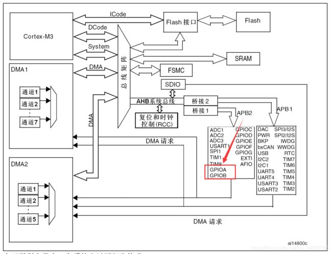
由rcc时钟树知道,因为GPIO挂载在APB2上 ,所以调用RCC_APB2PeriphClockCmd()来配置时钟,其函数原型为
void RCC_APB2PeriphClockCmd(uint32_t RCC_APB2Periph, FunctionalState NewState);
各变量的含义为:
@param RCC_APB2Periph: specifies the APB2 peripheral to gates its clock.
* This parameter can be any combination of the following values:
* @arg RCC_APB2Periph_AFIO, RCC_APB2Periph_GPIOA, RCC_APB2Periph_GPIOB,
* RCC_APB2Periph_GPIOC, RCC_APB2Periph_GPIOD, RCC_APB2Periph_GPIOE,
* RCC_APB2Periph_GPIOF, RCC_APB2Periph_GPIOG, RCC_APB2Periph_ADC1,
* RCC_APB2Periph_ADC2, RCC_APB2Periph_TIM1, RCC_APB2Periph_SPI1,
* RCC_APB2Periph_TIM8, RCC_APB2Periph_USART1, RCC_APB2Periph_ADC3,
* RCC_APB2Periph_TIM15, RCC_APB2Periph_TIM16, RCC_APB2Periph_TIM17,
* RCC_APB2Periph_TIM9, RCC_APB2Periph_TIM10, RCC_APB2Periph_TIM11
指定外围设备来配置它的时钟
* @param NewState: new state of the specified peripheral clock.
* This parameter can be: ENABLE or DISABLE.
选择该时钟的开或者关
3.将上述配置过程封装成函数,便于下次使用
以配置LED_R为例
void LED_R_GPIO_Config(void)
{

	GPIO_InitTypeDef GPIO_InitStruct;

	GPIO_InitStruct.GPIO_Pin = LED_R_GPIO_PIN;
	GPIO_InitStruct.GPIO_Mode = GPIO_Mode_Out_PP;//推挽输出
	GPIO_InitStruct.GPIO_Speed = GPIO_Speed_50MHz;

	GPIO_Init(LED_R_GPIO_PORT, &GPIO_InitStruct);


	RCC_APB2PeriphClockCmd(LED_R_GPIO_CLK, ENABLE);

}
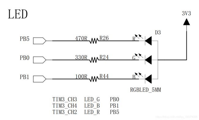
至此,初始化完毕,可以在main函数中调用,又因为板子上的灯是低电平亮,所以一旦配置完成默认输出低电平,灯亮
int main(void)
{
    while(1)
    {
	    LED_R_GPIO_Config();
    }
}
若要控制GPIO向其发送高/低电平,可以使用stm32f10x_gpio中的
//至1
GPIO_ResetBits(LED_G_GPIO_PORT, LED_G_GPIO_PIN);
//至0
GPIO_SetBits(LED_G_GPIO_PORT, LED_G_GPIO_PIN);

