- ASCIITable(ASCII表格):使用Arduino的高等的串口输出函数。
- 调光器:移动鼠标来改变LED灯的亮度
- 图表:发送数据到电脑,然后在Processing里画出它的图表。
- Midi(乐器数字接口):连续发送MIDI音符信息
- 多串口Mega:使能Arduino Mega上2个串口。
- 物理像素:通过从Processing或者Max/MSP发送数据到Arduino上,使LED开关。
- 读取ASCII字符串:分析整数里一个用逗号分隔的字符串,来使一个LED灯褪色。
- 串口呼叫响应:通过一个呼-应的方法(握手)来发送多个变数
- 串口呼叫响应ASCII:通过一个呼-应的方法(握手)来发送多个变数,并在发送前解码(ASCII)这些数值。
- Serial Event:使用SerialEvent()函数
- 可视颜色混合器:从Arduino发送多个变数到你的电脑,然后在Processing或者Max/MSP上读取这些数据
ASCIITable(ASCII表格)
这个例子示范了领先的串口打印函数,在串口监视器产生字符表格和它们在decimal,hexadecimal, octal, 和 binary的ASCII值。更多关于ASCII,请参考http://www.asciitable.com//en.wikipedia.org/wiki/ASCII
无其他要求,只要开发板通过串口或者USB口连接到电脑。
示例代码:
程序等待setup()函数的串口连接,然后一行一行打印ASCII表格直至最后一个字符。当完成这个步骤,如果没有其他事,它会进入无止尽的循环。关闭和打开串口监视窗口将会使开发板复位,从而使程序重新开始运行。
void setup() {
  //Initialize serial and wait for port to open:
  Serial.begin(9600);
  while (!Serial) {
    ; // wait for serial port to connect. Needed for native USB port only
  }

  // prints title with ending line break
  Serial.println("ASCII Table ~ Character Map");
}

// first visible ASCIIcharacter '!' is number 33:
int thisByte = 33;
// you can also write ASCII characters in single quotes.
// for example, '!' is the same as 33, so you could also use this:
// int thisByte = '!';

void loop() {
  // prints value unaltered, i.e. the raw binary version of the byte.
  // The Serial Monitor interprets all bytes as ASCII, so 33, the first number,
  // will show up as '!'
  Serial.write(thisByte);

  Serial.print(", dec: ");
  // prints value as string as an ASCII-encoded decimal (base 10).
  // Decimal is the default format for Serial.print() and Serial.println(),
  // so no modifier is needed:
  Serial.print(thisByte);
  // But you can declare the modifier for decimal if you want to.
  // this also works if you uncomment it:

  // Serial.print(thisByte, DEC);


  Serial.print(", hex: ");
  // prints value as string in hexadecimal (base 16):
  Serial.print(thisByte, HEX);

  Serial.print(", oct: ");
  // prints value as string in octal (base 8);
  Serial.print(thisByte, OCT);

  Serial.print(", bin: ");
  // prints value as string in binary (base 2) also prints ending line break:
  Serial.println(thisByte, BIN);

  // if printed last visible character '~' or 126, stop:
  if (thisByte == 126) {    // you could also use if (thisByte == '~') {
    // This loop loops forever and does nothing
    while (true) {
      continue;
    }
  }
  // go on to the next character
  thisByte++;
}

调光器
这个例子展示怎么从个人电脑发送数据到Arduino或者Genuino开发板来控制LED的亮度。这个数据是用特定的字节发送,每个数据的范围从0-255.程序读取三个字节,并且用它来设置LED的亮度。
你可以从任何可以接入电脑串口的软件发送字节到开发板。
LED灯串联一个220 ohm限流电阻,再连接到数字引脚pin9。LED的长腿(正极或者阳极)应该连到电阻的输出端,而短腿(负极或者阴极)连接到地。

const int ledPin = 9;      // the pin that the LED is attached to

void setup() {
  // initialize the serial communication:
  Serial.begin(9600);
  // initialize the ledPin as an output:
  pinMode(ledPin, OUTPUT);
}

void loop() {
  byte brightness;

  // check if data has been sent from the computer:
  if (Serial.available()) {
    // read the most recent byte (which will be from 0 to 255):
    brightness = Serial.read();
    // set the brightness of the LED:
    analogWrite(ledPin, brightness);
  }
}
官网的这个例程可能效果病不十分显著。
图表
这个例子展示怎么从Arduino或者Genuino发送字节数据到个人电脑,并用图表绘制结果。这个叫串口通讯,因为开发板和电脑似乎通过串口连接,即使它实际用USB接口,一个串口-USB和一个USB-串口转换器。
你可以用Arduino IDE的串口监视器来观察发送的数据,或者它可以通过 Processing (看下面的代码), Flash, PD, Max/MSP等读取。
连接电位计或者其他模拟传感器到模拟输入引脚A0
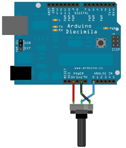
用上面代码例子里的Processing程序,你可以获得一个传感值图表。随着你改变传感器的值,你会获得像下面那样的东西:
const int lowestPin = 2;
const int highestPin = 13;


void setup() {
  // set pins 2 through 13 as outputs:
  for (int thisPin = lowestPin; thisPin <= highestPin; thisPin++) {
    pinMode(thisPin, OUTPUT);
  }
}

void loop() {
  // iterate over the pins:
  for (int thisPin = lowestPin; thisPin <= highestPin; thisPin++) {
    // fade the LED on thisPin from off to brightest:
    for (int brightness = 0; brightness < 255; brightness++) {
      analogWrite(thisPin, brightness);
      delay(2);
    }
    // fade the LED on thisPin from brightest to off:
    for (int brightness = 255; brightness >= 0; brightness--) {
      analogWrite(thisPin, brightness);
      delay(2);
    }
    // pause between LEDs:
    delay(100);
  }
}
Midi(乐器数字接口)
这个教程展示怎么从Arduino或者Genuino开发板通过一个5极DIN电缆来发送MIDI音符到一个MIDI乐器。
MIDI,乐器的数字接口,一个用于控制合成器,音序器,和其他音乐设备的协议。MIDI设备通常分为两大类:控制器(基于人的动作来产生MIDI信号的设备)和合成器(包括采样器,音序器等等)。后者输入MIDI数据,就会产生声音,光,或者其他的东西。
MIDI使一个串口协议,可以每秒钟操作31,250字节。开发板的内置串口接口(所有在Mega上的串口接口都一样)可以在那个速率上发送数据。
MIDI字节被分成两类型:命令字节和数据字节。命令字节通常是大于128,或者0x80到0xFF(十六进制)。数据字节通常少于127,或者0x00到0x7F(十六进制)。命令包括类似note on, note off, pitch bend等等。数据字节包括弹奏音符的音高,速率,或者,音符音量,弯音等等。更多细节,查看MIDI特性或者MIDI Protocol Guides on the Web。
MIDI数据通常用十六进制符号表示,因为MIDI音阶和乐器被分成16组。
根据MIDI说明书,所有MIDI连接器都是母座。这里是怎样把连接器连接到开发板。
MIDI插座pin5通过220 ohm电阻连接到数字引脚pin1。
MIDI插座pin2连接到地。
MIDI插座pin4通过220 ohm电阻连接到+5V。

示例代码:
注意:如果你用带有ATmega3U4的开发板(如DUE或者Leonardo),请根据下面程序用Serial1来替换Serial。
void setup() {
  // Set MIDI baud rate:
  Serial.begin(31250);
}

void loop() {
  // play notes from F#-0 (0x1E) to F#-5 (0x5A):
  for (int note = 0x1E; note < 0x5A; note ++) {
    //Note on channel 1 (0x90), some note value (note), middle velocity (0x45):
    noteOn(0x90, note, 0x45);
    delay(100);
    //Note on channel 1 (0x90), some note value (note), silent velocity (0x00):
    noteOn(0x90, note, 0x00);
    delay(100);
  }
}

// plays a MIDI note. Doesn't check to see that cmd is greater than 127, or that
// data values are less than 127:
void noteOn(int cmd, int pitch, int velocity) {
  Serial.write(cmd);
  Serial.write(pitch);
  Serial.write(velocity);
}
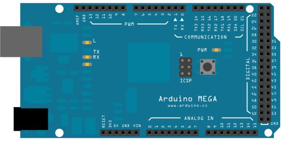
多串口Mega
很多时候一个串口不够用。当尝试和多个串口的设备通讯,同时发送数据回主串口窗口,一些额外的RX/TX连接口就变成很受欢迎的了。这个例子充分地利用了Arduino和Genuino Mega的3个辅助串口接口,使任何输入从连接器读取的数据直接发送到到主TX线,然后,发送到主串口窗口供观察。
检查你选择的串口设备的数据手册后,确保电源和连线没问题。把你设备的RX pin和TX pin连接到你Mega开发板的TX1和RX1,如原理图所示。
示例代码:
确保你的Mega开发板通过USB连接到你的电脑,启动串口通讯。
void setup() {
  // initialize both serial ports:
  Serial.begin(9600);
  Serial1.begin(9600);
}

void loop() {
  // read from port 1, send to port 0:
  if (Serial1.available()) {
    int inByte = Serial1.read();
    Serial.write(inByte);
  }

  // read from port 0, send to port 1:
  if (Serial.available()) {
    int inByte = Serial.read();
    Serial1.write(inByte);
  }
}
物理像素
这个例子示范了怎么用Arduino或者Genuino开发板来接受来自电脑的数据。当接受到字符“H”时,开发板打开LED;而接受到字符“L”时,开发板关闭LED灯。
数据从Arduino IDE串口监视器或者其他类似Processing,Flash,PD,Max/MSP之类的程序发送。
很多Arduino和Genuino开发板有一个连接到pin13的内置LED灯。如果你的开发板没有内置LED灯,连接一个额外的LED灯到pin13。长腿或者阳极,通过一个220 ohm电阻连接到pin13。短腿或者阴极,连接到地。

示例代码:
const int ledPin = 13; // the pin that the LED is attached to
int incomingByte;      // a variable to read incoming serial data into

void setup() {
  // initialize serial communication:
  Serial.begin(9600);
  // initialize the LED pin as an output:
  pinMode(ledPin, OUTPUT);
}

void loop() {
  // see if there's incoming serial data:
  if (Serial.available() > 0) {
    // read the oldest byte in the serial buffer:
    incomingByte = Serial.read();
    // if it's a capital H (ASCII 72), turn on the LED:
    if (incomingByte == 'H') {
      digitalWrite(ledPin, HIGH);
    }
    // if it's an L (ASCII 76) turn off the LED:
    if (incomingByte == 'L') {
      digitalWrite(ledPin, LOW);
    }
  }
}
读取ASCII字符串
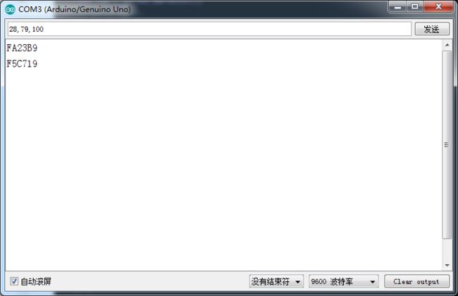
这个程序用Serial.parseInt()函数来定位非字母数字的字符的值。通常人们用逗号来区分信息的不同模块(这种格式通常叫comma-separated-values 或者 CSV),但其他字符像空格或者句号也可以用。这些值被粘贴成整数,用来区分RGB LED灯的颜色。你用Arduino IDE串口监视器来发送像“5,220,70”的字符串到你的开发板来改变灯光的颜色。
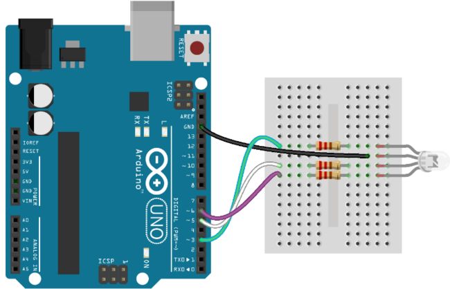
你需要4根线来连接上面的电路。一根把从开发板的电源处的5V连接到RGB LED灯的长引脚。
把RGB LED灯放在你的面包板上。检查你的LED灯的数据手册来判断引脚,它们应该是R,V+,G和B。从5V引来的线应该连接第二个引脚上,如电路图所示。
用剩下的线,连接LED灯的红阴极到pin3,绿阴极连接到pin5,蓝阴极连接到pin6,中间串联一个220ohm电阻。
共极的RGN LED灯分享一个共同的电源引脚。和使一个引脚切换高电平来点亮的LED灯不同,你需要使这个引脚切换成低电平,来产生一个电压差。所以,发送255到analogWrite()可以使LED关闭,而发送0会使它变得最亮。在下面的代码里,你用到一些数学公式,以便你能发送一些和亮度相应的数值。重要的是,和使用analogWrite(pin, brightness)不同,你要调用analogWrite(pin, 255-brightness).
示例代码:
// pins for the LEDs:
const int redPin = 3;
const int greenPin = 5;
const int bluePin = 6;

void setup() {
  // initialize serial:
  Serial.begin(9600);
  // make the pins outputs:
  pinMode(redPin, OUTPUT);
  pinMode(greenPin, OUTPUT);
  pinMode(bluePin, OUTPUT);

}

void loop() {
  // if there's any serial available, read it:
  while (Serial.available() > 0) {

    // look for the next valid integer in the incoming serial stream:
    int red = Serial.parseInt();
    // do it again:
    int green = Serial.parseInt();
    // do it again:
    int blue = Serial.parseInt();

    // look for the newline. That's the end of your sentence:
    //if (Serial.read() == '\n') {
      // constrain the values to 0 - 255 and invert
      // if you're using a common-cathode LED, just use "constrain(color, 0, 255);"
      red = 255 - constrain(red, 0, 255);
      green = 255 - constrain(green, 0, 255);
      blue = 255 - constrain(blue, 0, 255);

      // fade the red, green, and blue legs of the LED:
      analogWrite(redPin, red);
      analogWrite(greenPin, green);
      analogWrite(bluePin, blue);

      // print the three numbers in one string as hexadecimal:
      Serial.print(red, HEX);
      Serial.print(green, HEX);
      Serial.println(blue, HEX);
   // }
  }
}
注意:
用constrain(),你可以使这些值保持在PWM控制的范围内。用这种方式,如果这些值超过PWM的范围,它将会限制在一个可行的数值。从255里减去这个数值,你就可以得出用来控制LED灯的值。综上所述,当二极管和开发板的引脚之间有电压差时,这些LED灯会变亮

串口呼叫响应
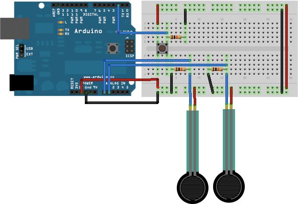
这个例子示范了用呼叫响应(握手)方式从Arduino 或Genuino开发板到电脑的多字节通讯。
这个程序在启动时发送一个ASCII A(字节值65),并且等它收到来自电脑的串口回应时重发。然后,它发送三个传感值作为单独字节,并且等待电脑的另一个回应。
你可以用Arduino IDE串口监视器来观察发送的数据,或者用Processing, Flash, PD, Max/MSP (看下面例子)等等来读取。
把模拟传感器(作为分压器)通过10k ohm电阻连接到模拟引脚PIN0和PIN1。
把一个按键或者开关连接到数字I/O口pin2,并通过一个10k ohm电阻下拉到地。

int firstSensor = 0;    // first analog sensor
int secondSensor = 0;   // second analog sensor
int thirdSensor = 0;    // digital sensor
int inByte = 0;         // incoming serial byte

void setup() {
  // start serial port at 9600 bps:
  Serial.begin(9600);
  while (!Serial) {
    ; // wait for serial port to connect. Needed for native USB port only
  }

  pinMode(2, INPUT);   // digital sensor is on digital pin 2
  establishContact();  // send a byte to establish contact until receiver responds
}

void loop() {
  // if we get a valid byte, read analog ins:
  if (Serial.available() > 0) {
    // get incoming byte:
    inByte = Serial.read();
    // read first analog input, divide by 4 to make the range 0-255:
    firstSensor = analogRead(A0) / 4;
    // delay 10ms to let the ADC recover:
    delay(10);
    // read second analog input, divide by 4 to make the range 0-255:
    secondSensor = analogRead(1) / 4;
    // read switch, map it to 0 or 255L
    thirdSensor = map(digitalRead(2), 0, 1, 0, 255);
    // send sensor values:
    Serial.write(firstSensor);
    Serial.write(secondSensor);
    Serial.write(thirdSensor);
  }
}

void establishContact() {
  while (Serial.available() <= 0) {
    Serial.print('A');   // send a capital A
    delay(300);
  }
}
串口呼叫响应ASCII
这个例子示范了用呼叫响应(握手)方式从Arduino 或Genuino开发板到电脑的串口通讯。
这个程序在启动时发送一个ASCII 字符串,并且等它收到来自电脑的串口回应时重发。然后,它发送三个传感值作为 ASCII解码的数字(逗号分开,换行+回车结束),并且等待电脑的另一个回应。
你可以用Arduino IDE串口监视器来观察发送的数据,或者用Processing, Flash, PD, Max/MSP (看下面例子)等等来读取。下面的例子用逗号分开输入的字符串,并转换成字符串重新输入到数字里。
比较这个和串口呼叫响应例子。他们在共同使用的握手方式上很相似,但这个把读到的传感值作为字符串解码,而另一个作为二进制值发送。而发送像ASCII-encoded的字符串承载更多的字节,这意味着你可以很容易发送比255更大的字节的传感器读取值。它同样容易在串口终端程序里读取。
把模拟传感器(作为分压器)通过10k ohm电阻连接到模拟引脚PIN0和PIN1。
把一个按键或者开关连接到数字I/O口pin2,并通过一个10k ohm电阻下拉到地。
int firstSensor = 0;    // first analog sensor
int secondSensor = 0;   // second analog sensor
int thirdSensor = 0;    // digital sensor
int inByte = 0;         // incoming serial byte

void setup() {
  // start serial port at 9600 bps and wait for port to open:
  Serial.begin(9600);
  while (!Serial) {
    ; // wait for serial port to connect. Needed for native USB port only
  }


  pinMode(2, INPUT);   // digital sensor is on digital pin 2
  establishContact();  // send a byte to establish contact until receiver responds
}

void loop() {
  // if we get a valid byte, read analog ins:
  if (Serial.available() > 0) {
    // get incoming byte:
    inByte = Serial.read();
    // read first analog input:
    firstSensor = analogRead(A0);
    // read second analog input:
    secondSensor = analogRead(A1);
    // read switch, map it to 0 or 255
    thirdSensor = map(digitalRead(2), 0, 1, 0, 255);
    // send sensor values:
    Serial.print(firstSensor);
    Serial.print(",");
    Serial.print(secondSensor);
    Serial.print(",");
    Serial.println(thirdSensor);
  }
}

void establishContact() {
  while (Serial.available() <= 0) {
    Serial.println("0,0,0");   // send an initial string
    delay(300);
  }
}
Serial Event
这个例子示范了怎么用SerialEvent()函数。这个函数是从loop()里调用。如果缓冲器有串口数据,每个被找到的字符都加入到一个字符串里,直到发现新行。在这种情况下,由收到的字符组成的字符串打印并且重置变回null。

什么都不要,只需要开发板连接到电脑。用Arduino IDE串口监视器发送单个或者多个字符并且返回字符串。
示例代码:
String inputString = "";         // a String to hold incoming data
boolean stringComplete = false;  // whether the string is complete

void setup() {
  // initialize serial:
  Serial.begin(9600);
  // reserve 200 bytes for the inputString:
  inputString.reserve(200);
}

void loop() {
  // print the string when a newline arrives:
  if (stringComplete) {
    Serial.println(inputString);
    // clear the string:
    inputString = "";
    stringComplete = false;
  }
}

/*
  SerialEvent occurs whenever a new data comes in the hardware serial RX. This
  routine is run between each time loop() runs, so using delay inside loop can
  delay response. Multiple bytes of data may be available.
*/
void serialEvent() {
  while (Serial.available()) {
    // get the new byte:
    char inChar = (char)Serial.read();
    // add it to the inputString:
    inputString += inChar;
    // if the incoming character is a newline, set a flag so the main loop can
    // do something about it:
    if (inChar == '\n') {
      stringComplete = true;
    }
  }
}

可视颜色混合器
这个例子示范了怎么从Arduino开发板发送多个数值到电脑。从三个电位计读到的数值被用来设置Processing或Max/MSP的后台颜色的红,绿和蓝零件。
连接模拟传感器到模拟引脚pin0,1,2。
这个电路用三个分压器来产生来自压力传感电阻的模拟电压。一个分压器有两个电阻串联,以便合理地分压。

示例代码:
这个传感值作为ASCII-encoded 数字从Arduino发送到电脑。这意味着每个数字是用ASCII字符“0”到“9”发送的。以“234”为例子,共发送了三个字节:ASCII "2" (binary value 50), ASCII "3" (binary value 51), 和ASCII "4" (binary value 52).
const int redPin = A0;      // sensor to control red color
const int greenPin = A1;    // sensor to control green color
const int bluePin = A2;     // sensor to control blue color

void setup() {
  Serial.begin(9600);
}

void loop() {
  Serial.print(analogRead(redPin));
  Serial.print(",");
  Serial.print(analogRead(greenPin));
  Serial.print(",");
  Serial.println(analogRead(bluePin));
}