前言
通过前篇文章《多视角三维模型纹理映射 01》,基本对OpenMVS框架和使用方法有了一个简单的理解,这里继续基于上一篇文章进行自己的探究,也对上篇文章中留下的问题进行解释。
已知:
1、手头有从8个角度拍摄的点云数据,且点云已经经过配准、融合、网格化形成了Mesh;
2、8个点云的外参(确认正确无误);
3、8个角度的图片;
原始点云是这样的:
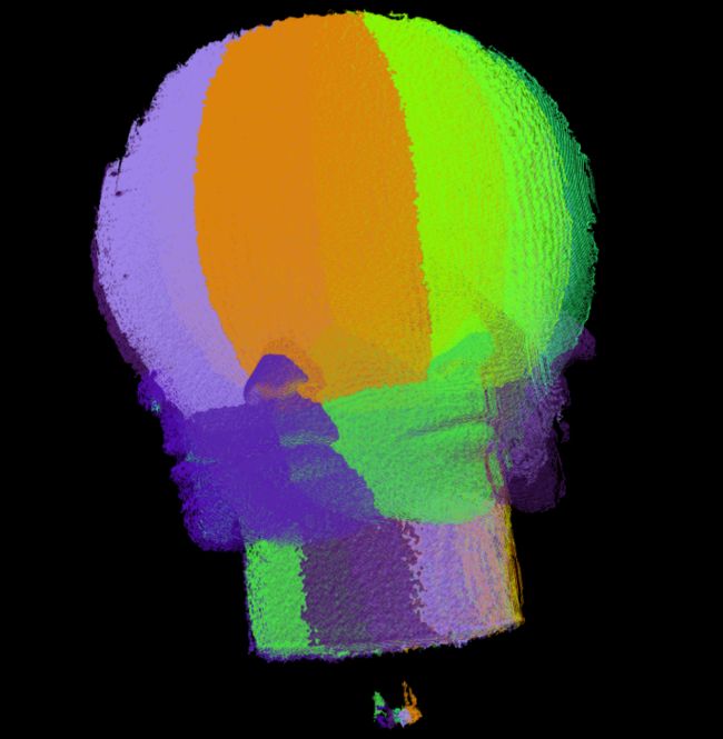
点云配准后如上篇文章《G2O与多视角点云全局配准优化》图片所示。
实现
基于OpenMVS,主要实现代码片段如下:
void texture() {

    int number_of_thread = 1;
    Scene scene(number_of_thread);

    Eigen::Matrix4d temp;
    std::string t_inPath = "./test/scene/1_in.txt";
    loadMat4(t_inPath, temp);
    Eigen::Matrix3d _k = temp.block<3, 3>(0, 0);  //相机内参
    //归一化
    _k(0, 0) = _k(0, 0) / 1600;
    _k(1, 1) = _k(1, 1) / 1600;
    _k(0, 2) = _k(0, 2) / 1600;
    _k(1, 2) = _k(1, 2) / 1600;

    { //填充platform
        Platform &plat = scene.platforms.AddEmpty();
        //1、name
        plat.name = "platform";

        CameraIntern &cam = plat.cameras.AddEmpty();

        cam.R = RMatrix::IDENTITY;
        cam.C = Point3(0, 0, 0);
        cam.K = _k;

        //已知 有8个相机位姿
        std::string matrix_path = "./test/scene/";
        for (int i = 1; i <= vieNum; ++i)
        {
            std::string _path = matrix_path + std::to_string(i) + "_ex.txt";
            Eigen::Matrix4d temp;
            loadMat4(_path, temp);

            Platform::Pose &pose = plat.poses.AddEmpty();
            pose.C = temp.block<3, 1>(0, 3);
            pose.R = temp.block<3, 3>(0, 0);

        }
    }

    {//填充images
        std::string imag_path = "test/image/";
        std::string matrix_path = "test/scene/";
        //ImageArr imgarr = scene.images;
        for (int i = 1; i <= vieNum; ++i) {
            std::string t_img = imag_path + std::to_string(i) + ".jpg";
            String _imgP(t_img);

            Image &_img = scene.images.AddEmpty();
            _img.ID = i-1;
            _img.platformID = 0;
            _img.cameraID = 0;
            _img.poseID = i-1;
            _img.LoadImage(_imgP);
            scene.images.push_back(_img);
        }

    }

    scene.mesh.Load("test/sm_mesh.ply");

    unsigned nResolutionLevel = 0;
    unsigned nMinResolution = 1280;
    float fOutlierThreshold = 0.f;
    float fRatioDataSmoothness = 0.0f;
    bool bGlobalSeamLeveling = true;
    bool bLocalSeamLeveling = true;
    unsigned nTextureSizeMultiple = 0;
    unsigned nRectPackingHeuristic = 0;

    bool res = scene.TextureMesh(nResolutionLevel, nMinResolution, fOutlierThreshold,
        fRatioDataSmoothness, bGlobalSeamLeveling, bLocalSeamLeveling,
        nTextureSizeMultiple, nRectPackingHeuristic);

    std::cout << "texture res:" << res << std::endl;

    //scene.Save("./test/res_tex.mvs",ARCHIVE_TEXT);
    scene.mesh.Save("test/res_tex.ply");
}按照上篇文章《多视角三维模型纹理映射 01》中所述,需要填充Scene中的相关数据成员。在这里我添加了一个Platform以及一个camera,然后添加了8个相机的Pose,这是符合自己的实际使用情况的,我有一个相机,拍摄了目标的8个角度的图像,所以我只有一个平台,一个相机,但是恢复了8个相机的位姿。
然后就是填充了8个Image,每一个Image的poseID需要和Platform中的Pose严格对应。
最后填充Mesh,直接使用了Load()函数。
释疑
针对上篇文章中的两个问题,以及自己为什么在这里以上述方式填充Platform,主要原因在于:
进入scene.TextureMesh()代码实现部分,在其视图选择模块中有
imageData.UpdateCamera(scene.platforms);一块代码,显然这是更新相机参数,更确切的,这是更新Image类中成员camera的;进一步的进入该代码:
// compute the camera extrinsics from the platform pose and the relative camera pose to the platform
//从platform计算相机外参
Camera Image::GetCamera(const PlatformArr& platforms, const Image8U::Size& resolution) const
{
    ASSERT(platformID != NO_ID);
    ASSERT(cameraID != NO_ID);
    ASSERT(poseID != NO_ID);

    // compute the normalized absolute camera pose
    //根据platformid提取该image对应的platform信息
    const Platform& platform = platforms[platformID];
    Camera camera(platform.GetCamera(cameraID, poseID));

    // compute the unnormalized camera
    //计算原始相机内参(归一化前的,真实相机内参)
    camera.K = camera.GetK(resolution.width, resolution.height);
    //将相机内外惨整合为3*4的仿射矩阵(P=KR[I|-C])
    camera.ComposeP();

    return camera;

} // GetCamera
void Image::UpdateCamera(const PlatformArr& platforms)
{
    camera = GetCamera(platforms, Image8U::Size(width, height));
} // UpdateCamera 从上述代码块可见,Image类中成员camera本质是从Platform中根据对应的ID提取计算的,也就是说Image::camera是依赖Platform的!最后进入platform.GetCamera(cameraID, poseID)代码实现部分:
// return the normalized absolute camera pose
Platform::Camera Platform::GetCamera(uint32_t cameraID, uint32_t poseID) const
{
    const Camera& camera = cameras[cameraID];
    const Pose& pose = poses[poseID];
    // add the relative camera pose to the platform
    Camera cam;
    cam.K = camera.K;
    cam.R = camera.R*pose.R;
    cam.C = pose.R.t()*camera.C+pose.C;
    return cam;
} // GetCamera从上述代码可见,真实参与纹理映射的是Image中camera,该camera的外参由Platform的camera和对应pose共同决定。
至此上述代码已经解释了:
- 上篇【问题1】:每张纹理图片对应的相机位姿其实是由
Platform中的相机和Platform中的位姿决定的 - 上篇【问题2】:没有必要在 ”外” 代码中填充实现
Image中的camera,无论怎么样填充该数据,它都会被Platform中的属性所覆盖。当然,前提是你已经正确填充了Paltform. - 上述源代码也解释了为什么在自己代码中,我只是创造了一个
Platform的Camera,并且所创造的Camera旋转矩阵为单位矩阵,平移矩阵为0的原因---Platform的Camera和Pose会同时参与Image中camera的计算,此时自己所填充的Platform的pose已经是正确且真实对应Image的位姿矩阵,所以没必要也无法再去填充Platfrom的camera。
实验
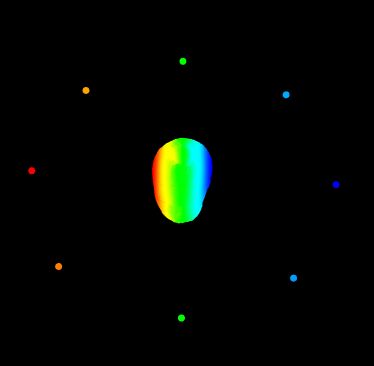
恢复的相机位姿与全局配准点云的关系如下:
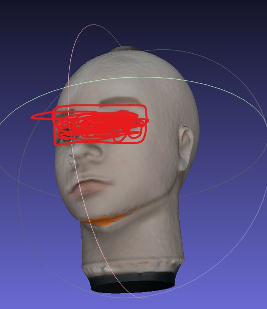
Mesh结果如图:
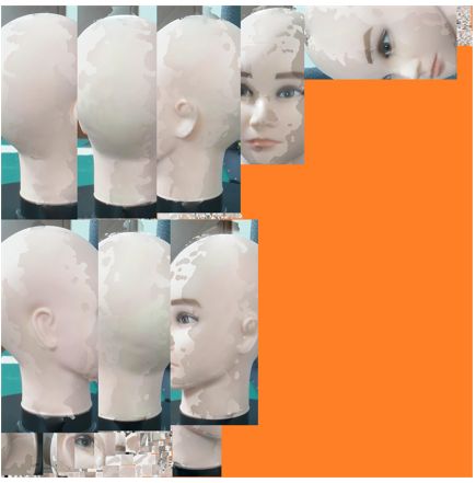
Mesh对应的合成纹理如下:
反思、总结
上述自己关于OpenMVS的理解,也不尽然完全正确,还有待进一步的提升,只是目前暂时达到了自己初步预想结果。
再来说一说外参。点云的外参表示点云的运动,相对的,点云外参的逆则表示所对应相机的运动,将所有点云做全局配准统一到世界坐标系下之后,每块点云外参的逆则代表了其所对应的相机在世界坐标系下的位姿矩阵。
另外,自己所使用的相机为RGB--D相机,即红外相机负责生成点云,RGB相机负责为点云提供纹理图,也就是说初始点云的坐标系是在红外相机下的,而纹理图则属于RGB相机,所以该RGB—D相机模组之间还有红外相机和RGB彩色相机的之间的标定,这里的标定矩阵,本质是点云的外参---将点云变换到RGB相机下才能贴图嘛!也正是因为使用的是RGB-D类型的相机,所以OpenMVS所需的矩阵才需要自己手动去填充(个人理解:OpenMVS是直接从RGB图像中恢复三维模型,然后贴图,不存在额外的点云到RGB的外参)。
再扯远一点,TexRecon也是专门用来解决网格纹理映射,它的输入也是mesh +camera+纹理图,与OpenMVS中不同,TexRecon中的camera其实是用点云的外参来填充!!但是TexRecon在进行纹理映射时候会对原始网格进行删减,可能会导致原本光滑的网格产生额外的孔洞,另外TexRecon依赖第三方(MVE等)比较多,这也是自己没有更加深入源码探讨的原因。
(TexRecon效果不是很好,不贴图了,或是自己使用并不是完全正确)
《Let There Be Color! Large-Scale Texturing of 3D Reconstructions》
留坑:
后续若有时间、精力,则进一步记录自己之前对转台的标定实现过程,也算是这几篇文章的前传吧。