卷积神经网络的卷积层
文章目录
- 卷积核
- 正向传播
- 反向传播
- 参考文献
- 附录
卷积核
笔者在学会了如何运用卷积神经网路后,突然有一天萌发了很多问题,为什么要用卷积核?卷积核具体完成了什么工作?带着这些疑问,笔者开始查询资料,其中一段视频(从“卷积”、到“图像卷积操作”、再到“卷积神经网络”,“卷积”意义的3次改变)对我的帮助很大。接下来,我们将略去卷积的数学意义,只从神经网路的角度来看卷积核。
卷积核其实就是一个具有学习能力的过滤器(也可以叫特征提取器,实际都是一个意思,过滤器就是过滤掉干扰,只留下特征)。卷积核在特征图上滑动,每移动一个步长,卷积核会与输入特征图出现重合区域,重合区域对应元素相乘、求和再加上偏置项得到输出图的一个像素点。
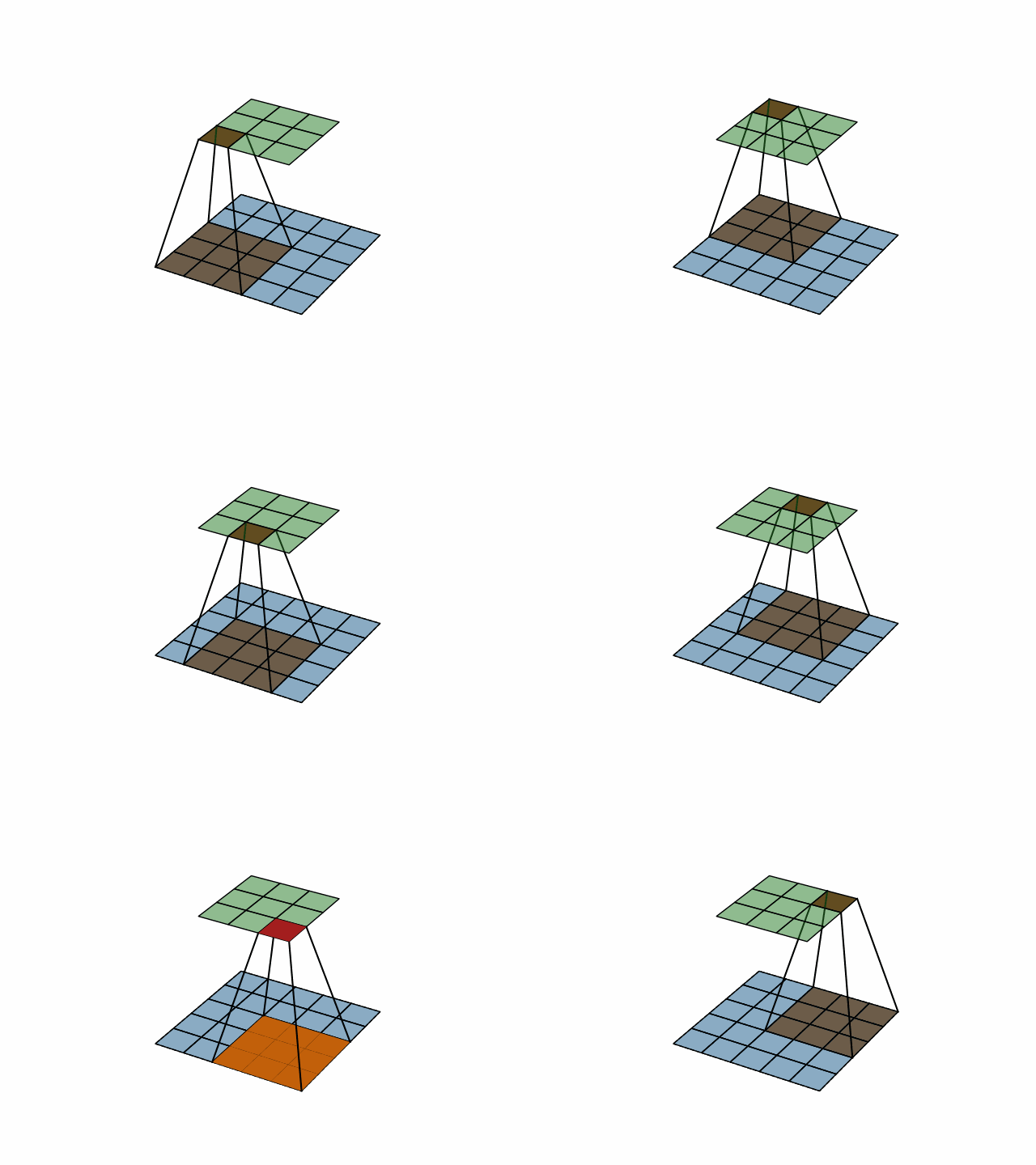
上图中,蓝色的为 5 × 5 5\times5 5×5 的输入特征图,在其上滑动的为 3 × 3 3\times3 3×3 的卷积核。绿色的为输出图。可以看到输入特征图与输出图的尺寸不一致,为了使两者保持一致,常常在输入特征图的四周填充像素点(取值通常为 0 0 0),如下图所示:
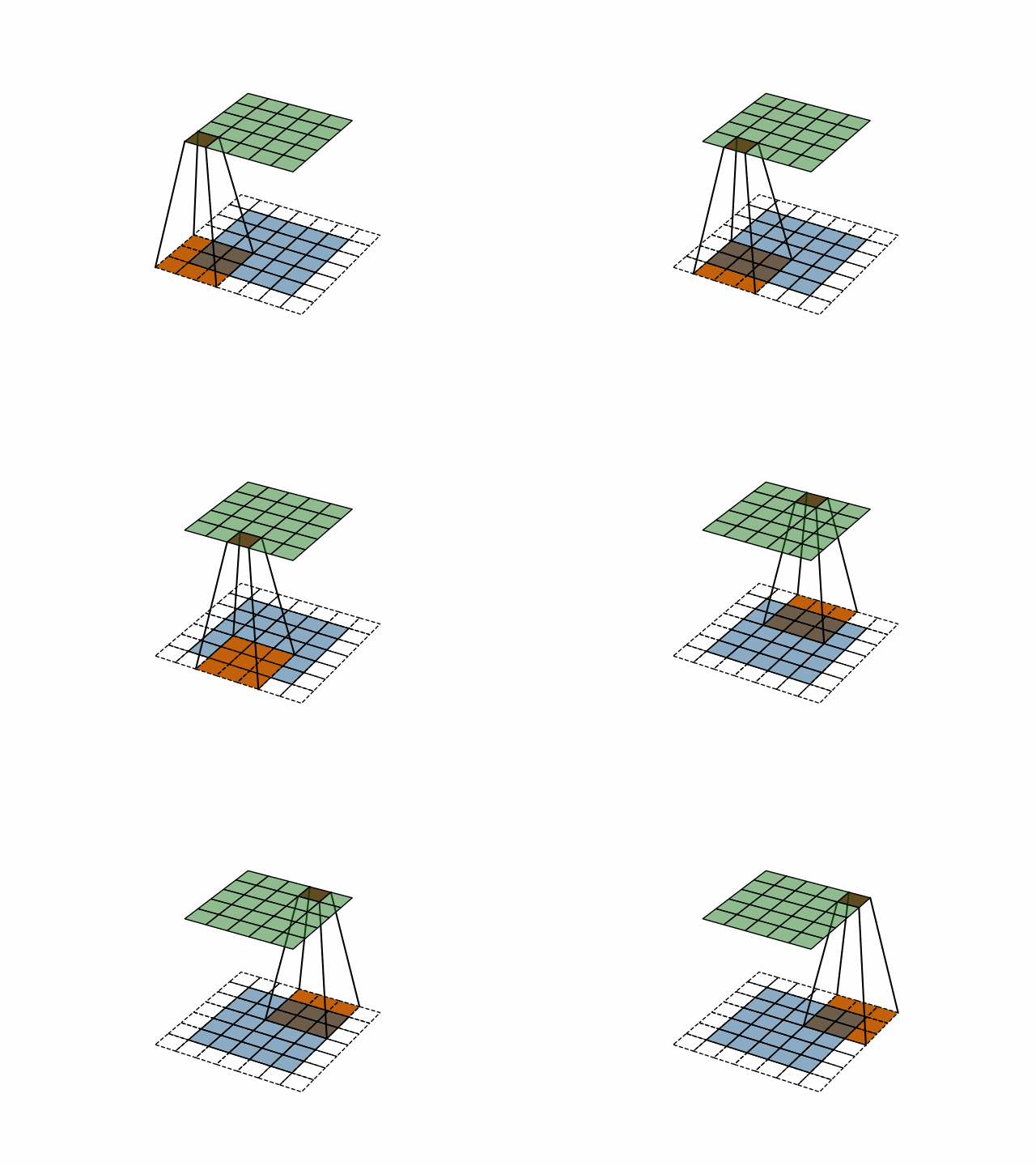
通过卷积核的运算,输入特征图上的一片区域可以映射到输出图中的一个像素点,这一片区域称为该像素点的感受野(receptive field)。如上图中,输出图中每个像素点在输入特征图中感受野的大小为 3 × 3 3\times3 3×3。
通过上图我们也可发现,输入特征图与输出图中对应像素点之间的区别就是,输出图中的像素点包含了输入特征图对应像素点及其周围 8 8 8 个像素点的信息。换个角度来说, 3 × 3 3\times3 3×3 的卷积核将 1 1 1 个像素点及其周围 1 1 1 圈像素点的信息融合为了 1 1 1 个像素点。以此类推, 5 × 5 5\times5 5×5 的卷积核将 1 1 1 个像素点及其周围 2 2 2 圈像素点的信息进行了融合。接下来,我们介绍几种常见的 3 × 3 3\times3 3×3 卷积核,来直观的了解卷积核的作用。
-
平滑卷积
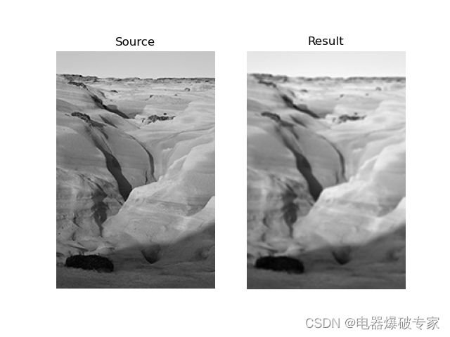
1 9 [ 1 1 1 1 1 1 1 1 1 ] \frac{1}{9} \left[ \begin{matrix} 1 & 1 & 1 \\ 1 & 1 & 1 \\ 1 & 1 & 1 \\ \end{matrix} \right] 91⎣ ⎡111111111⎦ ⎤ 通过以上表达式可以推测出:平滑卷积会让图像更加平滑,降低锐化。平滑卷积的作用效果如下:
-
锐化卷积
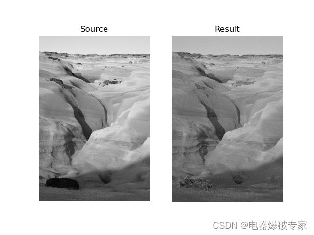
[ − 1 − 1 − 1 − 1 9 − 1 − 1 − 1 − 1 ] \left[ \begin{matrix} -1 & -1 & -1 \\ -1 & 9 & -1 \\ -1 & -1 & -1 \\ \end{matrix} \right] ⎣ ⎡−1−1−1−19−1−1−1−1⎦ ⎤ 该卷积核会利用周边像素信息来增强对比度,从而起到锐化的效果。锐化卷积的作用效果如下:
-
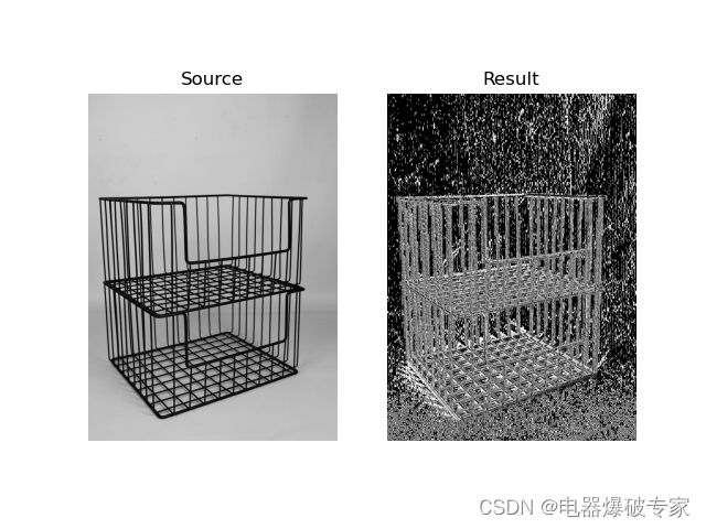
垂直梯度卷积
[ − 1 0 1 − 1 0 1 − 1 0 1 ] \left[ \begin{matrix} -1 & 0 & 1 \\ -1 & 0 & 1 \\ -1 & 0 & 1 \\ \end{matrix} \right] ⎣ ⎡−1−1−1000111⎦ ⎤ 该卷积核会增强图片中的垂直线条。其作用效果如下:
-
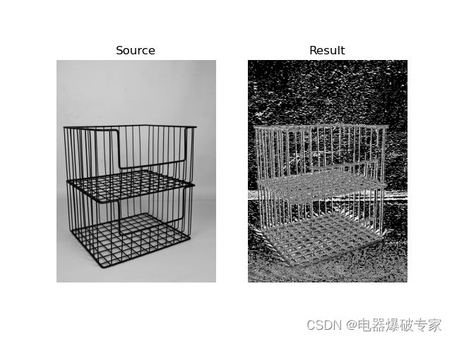
水平梯度卷积
[ − 1 − 1 − 1 0 0 0 1 1 1 ] \left[ \begin{matrix} -1 & -1 & -1 \\ 0 & 0 & 0 \\ 1 & 1 & 1 \\ \end{matrix} \right] ⎣ ⎡−101−101−101⎦ ⎤ 该卷积核会增强图片中的水平线条。其作用效果如下:
以上我们讨论的图像都是单通道图像(灰度图像),那么多通道图像(如:RGB 图像)该如何进行卷积呢?事实上,当图像的通道增加时,卷积核的 “厚度” 也会增加。例如:在 RGB 图像上应用 3 × 3 3\times3 3×3 的卷积核,卷积核的实际尺寸为 3 × 3 × 3 3\times3\times3 3×3×3,核内会有 27 27 27 个权重值。根据卷积核的运算过程,此时三通道的 RGB 图像最终卷积成了单通道的输出图。
我们也可以在一张图片上应用多个卷积核,让不同的卷积核提取不同的特征。在输出时,我们让每个卷积核的结果单独作为一个输出通道。这样我们在一张图片上应用 n n n 个卷积核就会产生 n n n 通道的输出图。
正向传播
在对卷积核进行简单介绍后,我们需要将其应用到神经网络中。首先要解决的就是实现上文中动画所展示的计算过程。作为程序员的第一直觉肯定是嵌套几个循环来解决。笔者一开始也是这样想的,但查阅过一些资料后,才发现这种做法虽然能得到正确的结果,但效率太低,无法利用矩阵运算资源。
设单通道 4 × 4 4\times4 4×4 特征图 I I I,尺寸为 3 × 3 3\times3 3×3 的卷积核 C C C,以及输出图 O O O。可使用矩阵将其表达为如下形式:
I = [ x 1 x 2 x 3 x 4 x 5 x 6 x 7 x 8 x 9 x 10 x 11 x 12 x 13 x 14 x 15 x 16 ] C = [ w 1 , 1 w 1 , 2 w 1 , 3 w 2 , 1 w 2 , 2 w 2 , 3 w 3 , 1 w 3 , 2 w 3 , 3 ] O = [ y 1 y 2 y 3 y 4 ] \begin{matrix} I= \left[ \begin{matrix} x_{1} & x_{2} & x_{3} & x_{4} \\ x_{5} & x_{6} & x_{7} & x_{8} \\ x_{9} & x_{10} & x_{11} & x_{12} \\ x_{13} & x_{14} & x_{15} & x_{16} \end{matrix} \right] & C= \left[ \begin{matrix} w_{1,1} & w_{1,2} & w_{1,3} \\ w_{2,1} & w_{2,2} & w_{2,3} \\ w_{3,1} & w_{3,2} & w_{3,3} \end{matrix} \right] & O= \left[ \begin{matrix} y_{1} & y_{2} \\ y_{3} & y_{4} \end{matrix} \right] \end{matrix} I=⎣ ⎡x1x5x9x13x2x6x10x14x3x7x11x15x4x8x12x16⎦ ⎤C=⎣ ⎡w1,1w2,1w3,1w1,2w2,2w3,2w1,3w2,3w3,3⎦ ⎤O=[y1y3y2y4] 显然 O = C ⋅ I O=C\cdot I O=C⋅I 不符合矩阵运算规则,也无法完成卷积计算过程。我们现在的想法是,寻找一种能完成卷积计算且符合矩阵运算规则的方法。因此我们分别对 I I I、 C C C、 O O O 进行如下变形:
I → flatten I ~ = [ x 1 x 2 x 3 x 4 x 5 x 6 x 7 x 8 x 9 x 10 x 11 x 12 x 13 x 14 x 15 x 16 ] I \xrightarrow{\text{flatten}} \widetilde{I} = \left[ \begin{matrix} x_{1} \\ x_{2} \\ x_{3} \\ x_{4} \\ x_{5} \\ x_{6} \\ x_{7} \\ x_{8} \\ x_{9} \\ x_{10} \\ x_{11} \\ x_{12} \\ x_{13} \\ x_{14} \\ x_{15} \\ x_{16} \end{matrix} \right] IflattenI =⎣ ⎡x1x2x3x4x5x6x7x8x9x10x11x12x13x14x15x16⎦ ⎤ C → C ~ = [ w 1 , 1 w 1 , 2 w 1 , 3 0 w 2 , 1 w 2 , 2 w 2 , 3 0 w 3 , 1 w 3 , 2 w 3 , 3 0 0 0 0 0 0 w 1 , 1 w 1 , 2 w 1 , 3 0 w 2 , 1 w 2 , 2 w 2 , 3 0 w 3 , 1 w 3 , 2 w 3 , 3 0 0 0 0 0 0 0 0 w 1 , 1 w 1 , 2 w 1 , 3 0 w 2 , 1 w 2 , 2 w 2 , 3 0 w 3 , 1 w 3 , 2 w 3 , 3 0 0 0 0 0 0 w 1 , 1 w 1 , 2 w 1 , 3 0 w 2 , 1 w 2 , 2 w 2 , 3 0 w 3 , 1 w 3 , 2 w 3 , 3 ] C \rightarrow \widetilde{C} = \left[ \begin{matrix} w_{1,1} & w_{1,2} & w_{1,3} & 0 & w_{2,1} & w_{2,2} & w_{2,3} & 0 & w_{3,1} & w_{3,2} & w_{3,3} & 0 & 0 & 0 & 0 & 0 \\ 0 & w_{1,1} & w_{1,2} & w_{1,3} & 0 & w_{2,1} & w_{2,2} & w_{2,3} & 0 & w_{3,1} & w_{3,2} & w_{3,3} & 0 & 0 & 0 & 0 \\ 0 & 0 & 0 & 0 & w_{1,1} & w_{1,2} & w_{1,3} & 0 & w_{2,1} & w_{2,2} & w_{2,3} & 0 & w_{3,1} & w_{3,2} & w_{3,3} & 0 & \\ 0 & 0 & 0 & 0 & 0 & w_{1,1} & w_{1,2} & w_{1,3} & 0 & w_{2,1} & w_{2,2} & w_{2,3} & 0 & w_{3,1} & w_{3,2} & w_{3,3} \\ \end{matrix} \right] C→C =⎣ ⎡w1,1000w1,2w1,100w1,3w1,2000w1,300w2,10w1,10w2,2w2,1w1,2w1,1w2,3w2,2w1,3w1,20w2,30w1,3w3,10w2,10w3,2w3,1w2,2w2,1w3,3w3,2w2,3w2,20w3,30w2,300w3,1000w3,2w3,100w3,3w3,2000w3,3⎦ ⎤ O → flatten O ~ = [ y 1 y 2 y 3 y 4 ] O \xrightarrow{\text{flatten}} \widetilde{O} = \left[ \begin{matrix} y_{1} \\ y_{2} \\ y_{3} \\ y_{4} \end{matrix} \right] OflattenO =⎣ ⎡y1y2y3y4⎦ ⎤ 这样 O ~ = C ~ ⋅ I ~ \widetilde{O} = \widetilde{C} \cdot \widetilde{I} O =C ⋅I 既符合矩阵运算规则又完成了卷积运算过程。此外,大多数卷积核内还设有一个偏置,但在上述公式中并未体现。 O ~ \widetilde{O} O 只需再做一次向量加法即可完成偏置的计算,这里不再展开。
反向传播
将卷积应用到神经网路,反向传播的过程也是必不可少的,只有这样才能完成卷积核内权重和偏置的更新。通过神经网路的基本原理一文,我们知道反向传播中每层需要完成两个计算工作。接下来,我们首先完成 “第一个工作” —— 根据损失值对本层的输出值的偏导,求损失值对上一层输出值的偏导。
我们继续沿用正向传播中使用的假设,以保持整体思路的连贯性。我们首先考虑求 ∂ ℓ ∂ x 1 \frac{\partial\ell}{\partial x_1} ∂x1∂ℓ。通过正向传播中的矩阵公式,我们发现 y 1 y_1 y1、 y 2 y_2 y2、 y 3 y_3 y3、 y 4 y_4 y4 都对 x 1 x_1 x1 有偏导,导致这个偏导关系的就是矩阵 C ~ \widetilde{C} C 的第一列。我们将 C ~ \widetilde{C} C
参考文献
1998 LeNet《Gradient-Based Learning Applied to Document Recognition》
2012 AlexNet 《ImageNet Classification with Deep Convolutional Neural Networks》
2014 VGGNet 《VERY DEEP CONVOLUTIONAL NETWORKS FOR LARGE-SCALE IMAGE RECOGNITION》
2014 InceptionNet v1 《Going deeper with convolutions》
2015 InceptionNet v2 v3 《Rethinking the Inception Architecture for Computer Vision》
2015 ResNet 《Deep Residual Learning for Image Recognition》
附录
生成卷积核动态演示图的代码如下:
import matplotlib.pyplot as plt
import numpy as np
import matplotlib.animation as animation

in_map_size = (5, 5)
kernel_size = (3, 3)
stride = (1, 1)
padding = (1, 1)

in_map_with_padding_size = (2 * padding[0] + in_map_size[0], 2 * padding[1] + in_map_size[1])
out_map_size = ((in_map_with_padding_size[0] - kernel_size[0] + 1) // stride[0],
                (in_map_with_padding_size[1] - kernel_size[1] + 1) // stride[1])
out_map_top_left = ((in_map_with_padding_size[0] - out_map_size[0]) // 2,
                    (in_map_with_padding_size[1] - out_map_size[1]) // 2)

ax = plt.axes(projection='3d')


def update(frame):
    kernel_top_left = ((frame // out_map_size[1]) * stride[0], (frame % out_map_size[1]) * stride[1])
    kernel_bottom_right = (kernel_top_left[0] + kernel_size[0], kernel_top_left[1] + kernel_size[1])
    kernel_top_right = (kernel_top_left[0], kernel_bottom_right[1])
    kernel_bottom_left = (kernel_bottom_right[0], kernel_top_left[1])
    pixel_top_left = ((frame // out_map_size[1]) + out_map_top_left[0], (frame % out_map_size[1]) + out_map_top_left[1])
    pixel_bottom_right = (pixel_top_left[0] + 1, pixel_top_left[1] + 1)
    pixel_top_right = (pixel_top_left[0], pixel_bottom_right[1])
    pixel_bottom_left = (pixel_bottom_right[0], pixel_top_left[1])
    ax.clear()
    ax.axis(False)
    x, y = np.meshgrid(np.arange(0, in_map_with_padding_size[0] + 1),
                       np.arange(0, in_map_with_padding_size[1] + 1))
    z = 0 * x
    ax.plot_surface(x, y, z, color='None', linestyle='--', edgecolor='black', zorder=1)
    x, y = np.meshgrid(np.arange(padding[0], padding[0] + in_map_size[0] + 1),
                       np.arange(padding[1], padding[1] + in_map_size[1] + 1))
    z = 0 * x
    ax.plot_surface(x, y, z, edgecolor='black', zorder=2, alpha=0.5)
    x, y = np.meshgrid(np.arange(kernel_top_left[0], kernel_bottom_right[0] + 1),
                       np.arange(kernel_top_left[1], kernel_bottom_right[1] + 1))
    z = 0 * x
    ax.plot_surface(x, y, z, zorder=3)
    x, y = np.meshgrid(np.arange(out_map_top_left[0], out_map_top_left[0] + out_map_size[0] + 1),
                       np.arange(out_map_top_left[1], out_map_top_left[1] + out_map_size[1] + 1))
    z = 0 * x + 1
    ax.plot_surface(x, y, z, edgecolor='black', zorder=4, alpha=0.5)
    x, y = np.meshgrid([pixel_top_left[0], pixel_bottom_right[0]], [pixel_top_left[1], pixel_bottom_right[1]])
    z = 0 * x + 1
    ax.plot_surface(x, y, z, zorder=5)
    x, y, z = [kernel_top_left[0], pixel_top_left[0]], [kernel_top_left[1], pixel_top_left[1]], [0, 1]
    ax.plot(x, y, z, color='black', zorder=6)
    x, y, z = [kernel_bottom_right[0], pixel_bottom_right[0]], [kernel_bottom_right[1], pixel_bottom_right[1]], [0, 1]
    ax.plot(x, y, z, color='black', zorder=6)
    x, y, z = [kernel_top_right[0], pixel_top_right[0]], [kernel_top_right[1], pixel_top_right[1]], [0, 1]
    ax.plot(x, y, z, color='black', zorder=6)
    x, y, z = [kernel_bottom_left[0], pixel_bottom_left[0]], [kernel_bottom_left[1], pixel_bottom_left[1]], [0, 1]
    ax.plot(x, y, z, color='black', zorder=6)


ani = animation.FuncAnimation(plt.gcf(), update, interval=500, frames=out_map_size[0] * out_map_size[1])
ani.save(r'test.gif')
plt.show()
生成卷积效果图的代码如下:
import matplotlib.image
import matplotlib.pyplot as plt
import numpy as np
import torch

conv = torch.nn.Conv2d(1, 1, (3, 3), bias=False)
# conv.weight.data = torch.ones(1, 1, 3, 3) / 9
# conv.weight.data = torch.Tensor([[[
#     [-1, -1, -1],
#     [-1, 9, -1],
#     [-1, -1, -1]
# ]]])
# conv.weight.data = torch.Tensor([[[
#     [-1, 0, 1],
#     [-1, 0, 1],
#     [-1, 0, 1]
# ]]])
conv.weight.data = torch.Tensor([[[
    [-1, -1, -1],
    [0, 0, 0],
    [1, 1, 1]
]]])

image = matplotlib.image.imread(r'C:\Users\11191\Desktop\10.jpg')   # 输入的必须是灰度图像
source = image.astype(np.float32)
source = torch.from_numpy(source[np.newaxis, np.newaxis, :, :])
result = conv(source)[0][0].detach().numpy()
result = result.astype(np.uint8)

axes1 = plt.subplot(121)
axes2 = plt.subplot(122)
axes1.axis(False)
axes2.axis(False)
axes1.imshow(image, cmap='gray')
axes2.imshow(result, cmap='gray')
axes1.set_title('Source')
axes2.set_title('Result')
plt.show()