esp笔记(8)驱动全彩 OLED(SSD1351)的显示
本文开发环境:
- MCU型号:ESP8266
- IDE环境 : Arduino IDE 1.8.9
- 1.27寸 全彩 OELD模块
本文内容:
- esp8266 使用 u8g2图形库 驱动 OELD 显示
- 自定义软件SPI接口
文章目录
- 一、简介
- 二、程序
-
- 2.1 IO口定义
- 2.2 模拟SPI写时序
- 2.3 驱动 OLED 模块
- 2.4 字符数组
- 三、源码与示例
-
- 3.1 完整源码
- 示例
一、简介
使用ESP8266模块(LoLin)驱动1.27寸全彩OLED:
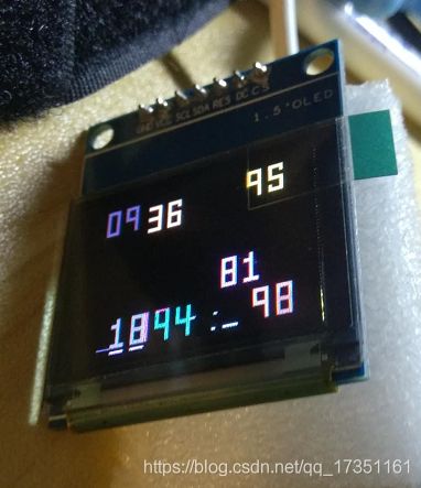
本文使用功的OLED为SSD1351驱动的全彩OLED,由于u8g2库没有支持SSD1351控制器,所以我们通过自己写驱动函数,来点亮一个SSD1351 驱动 OLED。本文代码来自网络。详见:ORIGINAL TUTORIAL
二、程序
2.1 IO口定义
本文使用的是模拟的 SPI 接口,首先有如下定义:
#define sclk 14        //WEMOS D5 pin
#define  mosi 13       //WEMOS D7
#define  cs 15         //WEMOS D8
const int DCpin =  4;  //WEMOS D2
const int RSTpin =  5; //WEMOS D1
这种定义的方法非常常见甚至必要,它可以让阅读代码的人一目了然,比如:
#define sclk 14 //WEMOS D5 pin
这段代码可以获取到的信息:模块的SCLK(SPI时钟线)接ESP8266的GPIO14脚,也就是WEMOS模块的丝印 D5 的IO口。同时,如果我们需要修改SCLK,也装修要修改该宏定义即可。
2.2 模拟SPI写时序
当我们定义好IO口以后,需要来模拟SPI的写时序:
void SPIwrite(uint8_t c){
  digitalWrite(sclk, HIGH);
  int8_t i; //signed intでなければならない。負の数になると255という値になって、例外エラーになる。
  for (i=7; i>=0; i--) {
      digitalWrite(sclk, LOW);
      if (c & _BV(i)) {
          digitalWrite(mosi, HIGH);
      } else {
          digitalWrite(mosi, LOW);
      }
      digitalWrite(sclk, HIGH);
  }
}
可以看到,我们发送了8个字节,所以模拟的是一次发送8个字节的SPI时序,注意到SPI协议不要求一次性只能发送8个,不过8个字节应该是最常见的。有了SPI 的时序,还可以进一步封装,将 SPI 写命令和写字节的函数封装:
void writeCommand(uint8_t c) {
    digitalWrite(DCpin, LOW);
    digitalWrite(cs, LOW);
    SPIwrite(c);
    digitalWrite(cs, HIGH);
}

void writeData(uint8_t c) {
    digitalWrite(DCpin, HIGH);
    digitalWrite(cs, LOW);
    SPIwrite(c);
    digitalWrite(cs, HIGH);
}
对于模块而已,DC脚的高低电平用来判断主机发送的字节是指令(cmd)还是数据(data),所以程序只需要拉低或拉高DC脚,然后调用SPIwrite(),写入字节即可。
2.3 驱动 OLED 模块
当写好写命令和指令的函数以后,就可以驱动OELD了,通常我们会参考官方的demo 或 数据手册,来完成一系列的写操作:
//****************SSD1351初期化*************************************************
void SSD1351_Init() {
	writeCommand(0xFD);
	//Set Command Lock
	writeData(0x12);
	//Unlock OLED driver IC MCU interface from entering command
	writeCommand(0xFD);
	//Set Command Lock
	writeData(0xB1);
	//Command A2,B1,B3,BB,BE,C1 accessible if in unlock state
	writeCommand(0xAE);
	//Sleep mode On (Display OFF)
	writeCommand(0xB3);
	//Front Clock Divider
	writeCommand(0xF1);
	// 7:4 = Oscillator Frequency, 3:0 = CLK Div Ratio (A[3:0]+1 = 1..16)
	writeCommand(0xCA);
	//Set MUX Ratio
	writeData(127);
	writeCommand(0xA0);
	//Set Re-map
	writeData(B01110100);
	//65k color
	//writeData(B10110100); //262k color
	//writeData(B11110100); //262k color, 16-bit format 2
	writeCommand(0x15);
	//Set Column
	writeData(0);
	//start
	writeData(127);
	//end
	writeCommand(0x75);
	//Set Row
	writeData(0);
	//start
	writeData(127);
	//end
	writeCommand(0xA1);
	//Set Display Start Line
	writeData(0);
	writeCommand(0xA2);
	//Set Display Offset
	writeData(0);
	writeCommand(0xB5);
	//Set GPIO
	writeData(0);
	writeCommand(0xAB);
	//Function Selection
	writeData(0x01);
	//Enable internal Vdd /8-bit parallel
	//writeData(B01000001); //Enable internal Vdd /Select 16-bit parallel interface
	writeCommand(0xB1);
	//Set Reset(Phase 1) /Pre-charge(Phase 2)
	//writeCommand(B00110010); //5 DCLKs / 3 DCLKs
	writeCommand(0x74);
	writeCommand(0xBE);
	//Set VCOMH Voltage
	writeCommand(0x05);
	//0.82 x VCC [reset]
	writeCommand(0xA6);
	//Reset to normal display
	writeCommand(0xC1);
	//Set Contrast
	writeData(0xC8);
	//Red contrast (reset=0x8A)
	writeData(0x80);
	//Green contrast (reset=0x51)
	writeData(0xC8);
	//Blue contrast (reset=0x8A)
	writeCommand(0xC7);
	//Master Contrast Current Control
	writeData(0x0F);
	//0-15
	writeCommand(0xB4);
	//Set Segment Low Voltage(VSL)
	writeData(0xA0);
	writeData(0xB5);
	writeData(0x55);
	writeCommand(0xB6);
	//Set Second Precharge Period
	writeData(0x01);
	//1 DCLKS
	writeCommand(0x9E);
	//Scroll Stop Moving
	writeCommand(0xAF);
	//Sleep mode On (Display ON)
}
可以看到,我们通过写指令和数据来对OLED进行设置,如解锁,时钟频率,颜色模式等等。如果你想进一步了解:参考资料
2.4 字符数组
在驱动OELD以后,就可以通过写指令指定OELD在屏幕的某一个坐标绘制一个带颜色的点,一个字符通常就是这些坐标的集合,所以我们可以通过数组的形式,来表示字符:
uint8_t bicho [16] ={0x0,0x0,0x66,0x7E,0x3C,0x18,0xFF,0x99,0x3C,0xFF,0xBD,0xBD,0x99,0x81,0x0,0x0};

uint8_t empty [16] = {0x00,0x00,0x00,0x00,0x00,0x00,0x00,0x00,0x00,0x00,0x00,0x00,0x00,0x00,0x00,0x00};//erases one character
uint8_t zero [16] = {0xff,0xff,0xc3,0xc3,0xc3,0xc3,0xc3,0xc3,0xc3,0xc3,0xc3,0xc3,0xc3,0xc3,0xff,0xff};//goes like a scanner
uint8_t one  [16] = {0x18,0x18,0x18,0xf8,0xf8,0x18,0x18,0x18,0x18,0x18,0x18,0x18,0x18,0x18,0xff,0xff};//goes like a scanner
uint8_t two  [16] = {0xff,0xff,0xc3,0xc3,0x03,0x03,0x03,0xff,0xff,0xc0,0xc0,0xc0,0xc3,0xc3,0xff,0xff};//goes like a scanner
uint8_t three[16] = {0xff,0xff,0x03,0x03,0x03,0x03,0x03,0xff,0xff,0x03,0x03,0x03,0x03,0x03,0xff,0xff};//goes like a scanner
uint8_t four [16] = {0xc3,0xc3,0xc3,0xc3,0xc3,0xc3,0xc3,0xff,0xff,0x03,0x03,0x03,0x03,0x03,0x03,0x03};//goes like a scanner
uint8_t five [16] = {0xff,0xff,0xc3,0xc3,0xc0,0xc0,0xc0,0xff,0xff,0x03,0x03,0x03,0xc3,0xc3,0xff,0xff};//goes like a scanner
uint8_t six  [16] = {0xff,0xff,0xc3,0xc3,0xc0,0xc0,0xc0,0xff,0xff,0xc3,0xc3,0xc3,0xc3,0xc3,0xff,0xff};//goes like a scanner
uint8_t seven[16] = {0xff,0xff,0xc3,0xc3,0x03,0x03,0x03,0x03,0x03,0x03,0x03,0x03,0x03,0x03,0x03,0x03};//goes like a scanner
uint8_t eight[16] = {0xff,0xff,0xc3,0xc3,0xc3,0xc3,0xc3,0xff,0xff,0xc3,0xc3,0xc3,0xc3,0xc3,0xff,0xff};//goes like a scanner
uint8_t nine [16] = {0xff,0xff,0xc3,0xc3,0xc3,0xc3,0xc3,0xff,0xff,0x03,0x03,0x03,0x03,0x03,0x03,0x03};//goes like a scanner
当OLED按照这些数据绘制像素点时,就会显示对应的字符了。我们需要一个绘制函数:
//****************等倍フォント表示*************************************************
void Font1x1(uint8_t StartX, uint8_t StartY, uint8_t Red, uint8_t Green, uint8_t Blue, uint8_t* buf) {
  int16_t i,j;
  uint8_t RGBbit1, RGBbit2;
  RGBbit1 = (Red<<3) | (Green>>3);
  RGBbit2 = (Green<<5) | Blue;
  writeCommand(0x15);
  //Set Column
  writeData(StartX);
  writeData(StartX+7);
  writeCommand(0x75);
  //Set Row
  writeData(StartY);
  writeData(StartY+15);
  writeCommand(0x5C);
  //Write RAM
  for (i=0; i<16; i++) {
    for (j=7; j>=0; j--) {
      if(buf[i] & _BV(j)) {
        writeData(RGBbit1);
        writeData(RGBbit2);
      } else {
        writeData(0);
        writeData(0);
      }
    }
  }
  yield();                 //避免软件看门狗复位
}
这个函数通过接收颜色数据,以及字符数据,来显示相应的内容。注意到,此处yield(),是博主添加的函数,为了避免软件看门狗复位,源程序无该语句,可能是程序完成时,编译器并没有软件开门狗。
三、源码与示例
3.1 完整源码
以下是完整的源码:
 * It does not work with Arduino UNO.
 * Scavenged by Javier Muñoz [email protected], 22/12/2016
 * ORIGINAL TUTORIAL FROM:(japanese) https://translate.google.com/translate?hl=en&sl=/auto&tl=en&u=https%3A%2F%2Fwww.mgo-tec.com%2Fblog-entry-adafruit-oled-ssd1351-esp-wroom-nonlib.html&sandbox=1
 */
//we dont need to include SPI.h to use it, arduino christmas magic
#define sclk 14   //WEMOS D5 pin
#define  mosi 13  //WEMOS D7
#define  cs 15    //WEMOS D8
const int DCpin =  4;
//WEMOS D2
const int RSTpin =  5;
//WEMOS D1
uint8_t bicho [16] = {
  0x0,0x0,0x66,0x7E,0x3C,0x18,0xFF,0x99,0x3C,0xFF,0xBD,0xBD,0x99,0x81,0x0,0x0
}
;
uint8_t empty [16] = {
  0x00,0x00,0x00,0x00,0x00,0x00,0x00,0x00,0x00,0x00,0x00,0x00,0x00,0x00,0x00,0x00
}
;
//erases one character
uint8_t zero [16] = {
  0xff,0xff,0xc3,0xc3,0xc3,0xc3,0xc3,0xc3,0xc3,0xc3,0xc3,0xc3,0xc3,0xc3,0xff,0xff
}
;
//goes like a scanner
uint8_t one  [16] = {
  0x18,0x18,0x18,0xf8,0xf8,0x18,0x18,0x18,0x18,0x18,0x18,0x18,0x18,0x18,0xff,0xff
}
;
//goes like a scanner
uint8_t two  [16] = {
  0xff,0xff,0xc3,0xc3,0x03,0x03,0x03,0xff,0xff,0xc0,0xc0,0xc0,0xc3,0xc3,0xff,0xff
}
;
//goes like a scanner
uint8_t three[16] = {
  0xff,0xff,0x03,0x03,0x03,0x03,0x03,0xff,0xff,0x03,0x03,0x03,0x03,0x03,0xff,0xff
}
;
//goes like a scanner
uint8_t four [16] = {
  0xc3,0xc3,0xc3,0xc3,0xc3,0xc3,0xc3,0xff,0xff,0x03,0x03,0x03,0x03,0x03,0x03,0x03
}
;
//goes like a scanner
uint8_t five [16] = {
  0xff,0xff,0xc3,0xc3,0xc0,0xc0,0xc0,0xff,0xff,0x03,0x03,0x03,0xc3,0xc3,0xff,0xff
}
;
//goes like a scanner
uint8_t six  [16] = {
  0xff,0xff,0xc3,0xc3,0xc0,0xc0,0xc0,0xff,0xff,0xc3,0xc3,0xc3,0xc3,0xc3,0xff,0xff
}
;
//goes like a scanner
uint8_t seven[16] = {
  0xff,0xff,0xc3,0xc3,0x03,0x03,0x03,0x03,0x03,0x03,0x03,0x03,0x03,0x03,0x03,0x03
}
;
//goes like a scanner
uint8_t eight[16] = {
  0xff,0xff,0xc3,0xc3,0xc3,0xc3,0xc3,0xff,0xff,0xc3,0xc3,0xc3,0xc3,0xc3,0xff,0xff
}
;
//goes like a scanner
uint8_t nine [16] = {
  0xff,0xff,0xc3,0xc3,0xc3,0xc3,0xc3,0xff,0xff,0x03,0x03,0x03,0x03,0x03,0x03,0x03
}
;
//goes like a scanner
//String numeros[10] = { "one", "two", "three","four","five","six","seven","eight","nine" };
uint8_t *pointernumeros[10];
//****************セットアップ*************************************************
void setup() {
  Serial.begin(9600);
  pointernumeros[0]=zero;
  pointernumeros[1]=one;
  pointernumeros[2]=two;
  pointernumeros[3]=three;
  pointernumeros[4]=four;
  pointernumeros[5]=five;
  pointernumeros[6]=six;
  pointernumeros[7]=seven;
  pointernumeros[8]=eight;
  pointernumeros[9]=nine;
  pinMode(DCpin, OUTPUT);
  pinMode(sclk, OUTPUT);
  pinMode(mosi, OUTPUT);
  pinMode(RSTpin, OUTPUT);
  pinMode(cs, OUTPUT);
  digitalWrite(cs, LOW);
  digitalWrite(RSTpin, HIGH);
  delay(500);
  digitalWrite(RSTpin, LOW);
  delay(500);
  digitalWrite(RSTpin, HIGH);
  delay(500);
  SSD1351_Init();
  delay(100);
  SSD1351_BlackOut();
  uint8_t Red = 31, Green = 63, Blue = 31;
  //Max Red = 31, Max Green = 63, MaxBlue = 31
  int i=0;
  Font1x1(i, 48, Red, 0, 0, zero);
  i=i+10;
  Font1x1(i, 48, Red, 0, 0, one);
  i=i+10;
  Font1x1(i, 48, Red, 0, 0, two);
  i=i+10;
  Font1x1(i, 48, Red, 0, 0, three);
  i=i+10;
  Font1x1(i, 48, Red, 0, 0, four);
  i=i+10;
  Font1x1(i, 48, Red, 0, 0, five);
  i=i+10;
  Font1x1(i, 48, Red, 0, 0, six);
  i=i+10;
  Font1x1(i, 48, Red, 0, 0, seven);
  i=i+10;
  Font1x1(i, 48, Red, 0, 0, eight);
  i=i+10;
  Font1x1(i, 48, Red, 0, 0, nine);
  //  Font1x1(8, 0, Red, Green, Blue, font_a[1]);
  //  Font2x2(0, 16, Red, Green, Blue, font_a[0]);
  //  Font2x2(16, 16, Red, Green, Blue, font_a[1]);
  //
  //  Green = 0; Blue = 0;
  //  Font1x1(32, 32, Red, Green, Blue, font_a[0]);
  //  Font1x1(40, 32, Red, Green, Blue, font_a[1]);
  //
  //  Red = 0; Green = 63; Blue = 0;
  //  Font2x2(48, 48, Red, Green, Blue, font_a[0]);
  //  Font2x2(64, 48, Red, Green, Blue, font_a[1]);
  //
  //  Red = 0; Green = 0; Blue = 31;
  //  Font1x1(80, 80, Red, Green, Blue, font_a[0]);
  //  Font1x1(88, 80, Red, Green, Blue, font_a[1]);
  //
  //  Red = 31; Green = 63; Blue = 20;
  //  Font2x2(96, 96, Red, Green, Blue, font_a[0]);
  //  Font2x2(112, 96, Red, Green, Blue, font_a[1]);
  SSD1351_BlackOut();
}
//****************メインループ*************************************************
void loop() {
  int i=random(0, 100);
  int j=random(0, 100);
  WriteNumber99(i,i,j,i-j,i*8,j);
  //  Font2x2(i, j, j, i-j, i*8, bicho);//bug rain
  //THIS THING COUNTS 0-1000
  //    SSD1351_BlackOut();
  //    for(int y=0;y<10;y++){
  //     Font1x1(18, 48, 30, 63, 31, empty);
  //     Font1x1(18, 48, y*5, 63-y*5,0, pointernumeros[y]);
  //
  //  for(int j=0;j<10;j++){
  //     Font1x1(30, 48, 30, 63, 0, empty);
  //     Font1x1(30, 48, y*5, 63-y*5, 0, pointernumeros[j]);
  // delay(20);
  //    for(int i=0;i<10;i++){
  //     Font1x1(42, 48, 30, 63, 0, empty);
  //     Font1x1(42, 48,  y*5, 63-y*5, 0, pointernumeros[i]);
  //delay(20);
  //    }
  //  }
  //    }
}
//****************SSD1351初期化*************************************************
void SSD1351_Init() {
  writeCommand(0xFD);
  //Set Command Lock
  writeData(0x12);
  //Unlock OLED driver IC MCU interface from entering command
  writeCommand(0xFD);
  //Set Command Lock
  writeData(0xB1);
  //Command A2,B1,B3,BB,BE,C1 accessible if in unlock state
  writeCommand(0xAE);
  //Sleep mode On (Display OFF)
  writeCommand(0xB3);
  //Front Clock Divider
  writeCommand(0xF1);
  // 7:4 = Oscillator Frequency, 3:0 = CLK Div Ratio (A[3:0]+1 = 1..16)
  writeCommand(0xCA);
  //Set MUX Ratio
  writeData(127);
  writeCommand(0xA0);
  //Set Re-map
  writeData(B01110100);
  //65k color
  //writeData(B10110100); //262k color
  //writeData(B11110100); //262k color, 16-bit format 2
  writeCommand(0x15);
  //Set Column
  writeData(0);
  //start
  writeData(127);
  //end
  writeCommand(0x75);
  //Set Row
  writeData(0);
  //start
  writeData(127);
  //end
  writeCommand(0xA1);
  //Set Display Start Line
  writeData(0);
  writeCommand(0xA2);
  //Set Display Offset
  writeData(0);
  writeCommand(0xB5);
  //Set GPIO
  writeData(0);
  writeCommand(0xAB);
  //Function Selection
  writeData(0x01);
  //Enable internal Vdd /8-bit parallel
  //writeData(B01000001); //Enable internal Vdd /Select 16-bit parallel interface
  writeCommand(0xB1);
  //Set Reset(Phase 1) /Pre-charge(Phase 2)
  //writeCommand(B00110010); //5 DCLKs / 3 DCLKs
  writeCommand(0x74);
  writeCommand(0xBE);
  //Set VCOMH Voltage
  writeCommand(0x05);
  //0.82 x VCC [reset]
  writeCommand(0xA6);
  //Reset to normal display
  writeCommand(0xC1);
  //Set Contrast
  writeData(0xC8);
  //Red contrast (reset=0x8A)
  writeData(0x80);
  //Green contrast (reset=0x51)
  writeData(0xC8);
  //Blue contrast (reset=0x8A)
  writeCommand(0xC7);
  //Master Contrast Current Control
  writeData(0x0F);
  //0-15
  writeCommand(0xB4);
  //Set Segment Low Voltage(VSL)
  writeData(0xA0);
  writeData(0xB5);
  writeData(0x55);
  writeCommand(0xB6);
  //Set Second Precharge Period
  writeData(0x01);
  //1 DCLKS
  writeCommand(0x9E);
  //Scroll Stop Moving
  writeCommand(0xAF);
  //Sleep mode On (Display ON)
}
//****************全画面消去*************************************************
void SSD1351_BlackOut() {
  writeCommand(0x15);
  //Set Column
  writeData(0x00);
  writeData(127);
  writeCommand(0x75);
  //Set Row
  writeData(0x00);
  writeData(127);
  writeCommand(0x5C);
  //Write RAM
  for (int i=0; i<128*128; i++) {
    writeData(0x00);
    writeData(0x00);
    //writeData(0x00); //262k colorの場合3バイト分送信
  }
}
//****************等倍フォント表示*************************************************
void Font1x1(uint8_t StartX, uint8_t StartY, uint8_t Red, uint8_t Green, uint8_t Blue, uint8_t* buf) {
  int16_t i,j;
  uint8_t RGBbit1, RGBbit2;
  RGBbit1 = (Red<<3) | (Green>>3);
  RGBbit2 = (Green<<5) | Blue;
  writeCommand(0x15);
  //Set Column
  writeData(StartX);
  writeData(StartX+7);
  writeCommand(0x75);
  //Set Row
  writeData(StartY);
  writeData(StartY+15);
  writeCommand(0x5C);
  //Write RAM
  for (i=0; i<16; i++) {
    for (j=7; j>=0; j--) {
      if(buf[i] & _BV(j)) {
        writeData(RGBbit1);
        writeData(RGBbit2);
      } else {
        writeData(0);
        writeData(0);
      }
    }
  }
  yield();
}
//****************倍角フォント表示*************************************************
void Font2x2(uint8_t StartX, uint8_t StartY, uint8_t Red, uint8_t Green, uint8_t Blue, uint8_t* buf) {
  int16_t i,j,ii;
  uint8_t RGBbit1, RGBbit2;
  RGBbit1 = (Red<<3) | (Green>>3);
  RGBbit2 = (Green<<5) | Blue;
  writeCommand(0x15);
  //Set Column
  writeData(StartX);
  writeData(StartX+15);
  writeCommand(0x75);
  //Set Row
  writeData(StartY);
  writeData(StartY+31);
  writeCommand(0x5C);
  //Write RAM
  for (i=0; i<16; i++) {
    for (ii=0; ii<2; ii++) {
      //倍角の場合2行同じものを描く
      for (j=7; j>=0; j--) {
        if(buf[i] & _BV(j)) {
          writeData(RGBbit1);
          writeData(RGBbit2);
          writeData(RGBbit1);
          writeData(RGBbit2);
        } else {
          writeData(0);
          writeData(0);
          writeData(0);
          writeData(0);
        }
      }
    }
    yield();
  }
}
//****************SPIデータ処理*************************************************
void SPIwrite(uint8_t c) {
  digitalWrite(sclk, HIGH);
  int8_t i;
  //signed intでなければならない。負の数になると255という値になって、例外エラーになる。
  for (i=7; i>=0; i--) {
    digitalWrite(sclk, LOW);
    if (c & _BV(i)) {
      digitalWrite(mosi, HIGH);
    } else {
      digitalWrite(mosi, LOW);
    }
    digitalWrite(sclk, HIGH);
  }
}
void writeCommand(uint8_t c) {
  digitalWrite(DCpin, LOW);
  digitalWrite(cs, LOW);
  SPIwrite(c);
  digitalWrite(cs, HIGH);
}
void writeData(uint8_t c) {
  digitalWrite(DCpin, HIGH);
  digitalWrite(cs, LOW);
  SPIwrite(c);
  digitalWrite(cs, HIGH);
}
Write number 00 Up to to 99
void WriteNumber99(int number,int x,int y,int red,int green, int blue) {
  int unit=0;
  int dec=0;
  dec=number/10;
  unit=number-(dec*10);
  Serial.print(dec);
  Serial.print(" ");
  Serial.println(unit);
  Font1x1(x, y+32,red, green,blue, pointernumeros[dec]);
  Font1x1(x+12, y+32,red, green,blue, pointernumeros[unit]);
}
Write number 00 Up to to 999
void WriteNumber999(int number,int x,int y,int red,int green, int blue) {
  int unit=0;
  int dec=0;
  int cent=0;
  cent=number/100;
  dec=(number-(cent*100))/10;
  unit=number-(dec*10)-(cent*100);
  Serial.print( cent);
  Serial.print( " ");
  Serial.print( dec);
  Serial.print( " ");
  Serial.println( unit);
  Font1x1(x, y+32,red, green,blue, pointernumeros[cent]);
  //y has a offset of 32 because the code is for 128pixel screen
  Font1x1(x+12, y+32,red, green,blue, pointernumeros[dec]);
  Font1x1(x+24, y+32,red, green,blue, pointernumeros[unit]);
}
示例
本文源码的使用是简单的,首先将完整的源码编译下载,然后连线即可:
| OLED | ESP8266 | LoLin(WEMOS) |
|---|---|---|
| sclk | 14 | D5 |
| mosi | 13 | D7 |
| cs | 15 | D8 |
| DCpin | 4 | D2 |
| RSTpin | 5 | D1 |