Matlab学习——曲柄滑块的运动仿真
1、图解法
①机构位置分析的图解法
选取适当的长度比例尺
μ l = 0.6 : 1 {\mu _l} = 0.6:1 μl=0.6:1
选取曲柄l1的铰链中心A 点的位置,
按主动杆
r = 60 m m {\rm{r}} = 60mm r=60mm
连杆
l = 300 m m l = 300mm l=300mm
初始位置
θ 1 = 0 {\theta _1} = 0 θ1=0
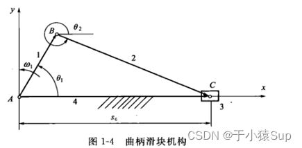
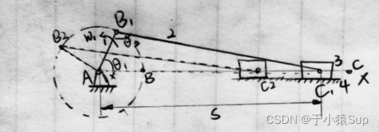
依次作图确定出滑块的导路位置线 x x xx xx和铰链中心B和C的位置,然后画出连杆2和滑块3的位置BC及C和两处的位置参数 θ 2 \theta_2 θ2 和 s s s的位置。
②速度分析的图解法(瞬心法)
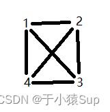
如上图所示,有构件数目为4,则瞬心数目为 C 4 2 = 6 C_4^2 = 6 C42=6。构件1和构件2、构件2和构件3、构件1和构件4的瞬心分别是转动副 p 12 {p_{12}} p12、 p 23 {p_{23}} p23、 p 14 {p_{14}} p14。构件3和构件4为移动副所以瞬心 p 34 {p_{34}} p34在垂直导路的方向无穷远处。根据瞬心多边形法分别求出 p 13 {p_{13}} p13、 p 24 {p_{24}} p24。
根据速度瞬心定理得
v p 13 → = ω 1 ( p 14 p 13 ‾ μ l ) \overrightarrow {{v_{{p_{13}}}}} = {\omega _1}(\overline {{p_{14}}{p_{13}}} {\mu _l}) vp13=ω1(p14p13μl)
则滑块的速度
v 3 → = v p 13 → \overrightarrow {{v_3}} = \overrightarrow {{v_{{p_{13}}}}} v3=vp13
③加速度分析的图解法
所以
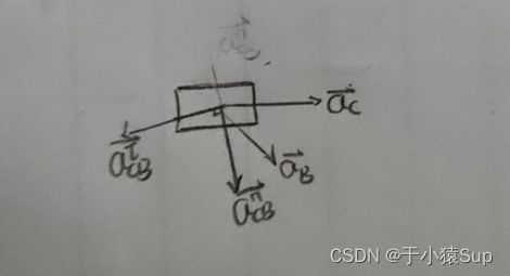
a C → = a B → + a C B n → + a C B τ → \overrightarrow {{a_C}} = \overrightarrow {{a_B}} + \overrightarrow {a_{CB}^n} + \overrightarrow {a_{CB}^\tau } aC=aB+aCBn+aCBτ
根据速度分析 ω 2 ω 1 = p 12 p 14 ‾ p 12 p 24 ‾ \frac{{{\omega _2}}}{{{\omega _1}}} = \frac{{\overline {{p_{12}}{p_{14}}} }}{{\overline {{p_{12}}{p_{24}}} }} ω1ω2=p12p24p12p14,可求出 ω 2 {\omega _2} ω2。
则 a B = ω 1 2 l 1 ( 已 知 ) , a C B n = ω 2 2 l 2 ( 已 知 ) , a C B τ = α 2 l 2 ( 大 小 未 知 ) {a_B} = {\omega _1}^2{l_1}(已知),a_{CB}^n = {\omega _2}^2{l_2}(已知),a_{CB}^\tau = {\alpha _2}{l_2}(大小未知) aB=ω12l1(已知),aCBn=ω22l2(已知),aCBτ=α2l2(大小未知)
滑块加速度为
a C = μ a p c ‾ {a_C} = {\mu _a}\overline {pc} aC=μapc
2、solidworks分析法
①滑块线位移曲线
②滑块线速度曲线
③滑块线加速度曲线
④连杆角位移曲线
⑤连杆角速度曲线
⑥连杆角加速度曲线
3、解析法
①位置分析
对封闭图形ABCA可知,封闭矢量方程式 (3-1)
l 1 → + l 2 → = s \overrightarrow {l1} + \overrightarrow {l2} = s l1+l2=s
转化为复数的形式(3-2)
l 1 e i θ 1 + l 2 e i θ 2 = s l1{e^{i{\theta _1}}} + l2{e^{i{\theta _2}}} = s l1eiθ1+l2eiθ2=s
根据欧拉公式(3-3)
e i θ = cos ( θ ) + sin ( θ ) i {e^{^{i\theta }}} = \cos (\theta ) + \sin (\theta )i eiθ=cos(θ)+sin(θ)i
将实部与虚部分离得 (3-4)
l 1 cos θ 1 + l 2 cos θ 2 = s l 1 sin θ 1 + l 2 sin θ 2 = 0 \begin{array}{l} l1\cos {\theta _1} + l2\cos {\theta _2} = s\\ l1\sin {\theta _1} + l2\sin {\theta _2} = 0 \end{array} l1cosθ1+l2cosθ2=sl1sinθ1+l2sinθ2=0
由上式得(3-5)
θ 2 = arcsin ( − l 1 sin θ 1 l 2 ) s = l 1 cos θ 1 + l 2 cos θ 2 \begin{array}{l} {\theta _2} = \arcsin (\frac{{ - l1\sin {\theta _1}}}{{l2}})\\ s = l1\cos {\theta _1} + l2\cos {\theta _2} \end{array} θ2=arcsin(l2−l1sinθ1)s=l1cosθ1+l2cosθ2
代码相关部分
theta2=asin((e-l1 * sin(theta1))/l2);

s=l1 * cos(theta1) + l2 * cos(theta2);
②速度分析
由(3-2)式对时间求一次导得速度关系(3-6)
i l 1 ω 1 e i θ 1 + i l 2 ω 2 e i θ 2 = v il1{\omega _1}{e^{i{\theta _1}}} + il2{\omega _2}{e^{i{\theta _2}}} = v il1ω1eiθ1+il2ω2eiθ2=v
将虚部与实部分离得(3-7)
l 1 ω 1 cos θ 1 + l 2 ω 2 cos θ 2 = 0 − l 1 ω 1 sin θ 1 − l 2 ω 2 sin θ 2 = v \begin{array}{l} l1{\omega _1}\cos {\theta _1} + l2{\omega _2}\cos {\theta _2} = 0\\ -l1{\omega _1}\sin {\theta _1} - l2{\omega _2}\sin {\theta _2} = v \end{array} l1ω1cosθ1+l2ω2cosθ2=0−l1ω1sinθ1−l2ω2sinθ2=v
用矩阵可表示为(3-8)
( l 2 sin θ 2 1 − l 2 cos θ 2 0 ) ( ω 2 v ) = ω 1 ( − l 1 sin θ 1 l 1 cos θ 1 ) {\begin{pmatrix} {l2\sin {\theta _2}}&1\\ { -l2\cos {\theta _2}}&0 \end{pmatrix}} \begin{pmatrix} {\omega _2}\\ v \end{pmatrix}= {\omega _1} \begin{pmatrix} -l1\sin {\theta _1}\\ l1\cos {\theta _1} \end{pmatrix} (l2sinθ2−l2cosθ210)(ω2v)=ω1(−l1sinθ1l1cosθ1)
可根据上式求出角速度 ω 2 {\omega _2} ω2和滑块速度v 。
代码相关部分
A=[l2*sin(theta2), 1; -l2*cos(theta2), 0];
B=[-l1*sin(theta1); l1*cos(theta1)];
% ‘\’求解关于 x 的线性方程组 Ax = B
%  eg: x=A\B
omega=A \ (omega1*B);
omega2=omega(1);
v=omega(2);
③加速度分析
由(3-6)式求一次导可得加速度关系式,矩阵表示为(3-9)
( l 2 sin θ 2 1 − l 2 cos θ 2 0 ) ( α 2 a ) + ( ω 2 l 2 cos θ 2 0 ω 2 l 2 sin θ 2 0 ) ( ω 2 v ) = ω 1 ( − ω 1 l 1 cos θ 1 − ω 1 l 1 sin θ 1 ) {\begin{pmatrix} {l2\sin {\theta _2}}&1\\ { -l2\cos {\theta _2}}&0 \end{pmatrix}} \begin{pmatrix} {\alpha _2}\\ a \end{pmatrix} + {\begin{pmatrix} {{\omega _2}l2\cos {\theta _2}}&0\\ {{\omega _2}l2\sin {\theta _2}}&0 \end{pmatrix}} \begin{pmatrix} {\omega _2}\\ v \end{pmatrix} = {\omega _1} \begin{pmatrix} -{\omega _1}l1\cos {\theta _1}\\ -{\omega _1}l1\sin {\theta _1} \end{pmatrix} (l2sinθ2−l2cosθ210)(α2a)+(ω2l2cosθ2ω2l2sinθ200)(ω2v)=ω1(−ω1l1cosθ1−ω1l1sinθ1)
代码相关部分
Aa=[omega2*l2*cos(theta2), 0;
	omega2*l2*sin(theta2), 0];
Ba= [-omega1*l1*cos(theta1);
	-omega1*l1*sin(theta1)];
alpha=A \(-Aa*omega+alpha1*B+omega1*Ba);
alpha2 = alpha(1);
a = alpha(2);
CODE
clear;
r = 60;  % 主动杆杆长
l = 300;  % 连杆杆长
e = 0;  % 偏心距
hd = pi/180;
du = 180/pi;
omega1 = 20; % 主动杆角速度
alpha1 = 0; % 主动杆角加速度

% for循环获取0-4pi构件2角位移、滑块位移、构件2角速度、滑块线速度、构件2角加速度、滑块线加速度
for n1= 1:720
    theta1(n1)=(n1-1)*hd;  % 0-4pi
    [theta2(n1) , s(n1) , omega2(n1), v(n1) , alpha2(n1), a(n1)] = slider_crank(theta1(n1) , omega1, alpha1, r, l, e);
end

figure(1);
n = 1:720;
% 位移曲线图
subplot(2, 2, 1);
yyaxis left;
plot(theta1*du, theta2*du);
ylabel('连杆角位移/(\circ)');
yyaxis right;
plot(theta1*du, s);
ylabel('滑块位移/mm');
xlabel('曲柄转角\theta_1/(\circ))');
title('位移曲线图');
xlim([0, 720]);
x_new = linspace(0, 720, 5);
xticks(x_new)
grid on;

%速度曲线图
subplot(2,2,2);
yyaxis left;
plot(theta1*du, omega2);
ylabel('连杆角速度/(rad/s)');
yyaxis right;
plot(theta1*du, v/1000);
ylabel('滑块速度/(m/s)');
xlabel('曲柄转角\theta_1/(\circ))');
xlim([0, 720]);
x_new = linspace(0, 720, 5);
xticks(x_new)
title('速度曲线图');
grid on;

%加速度曲线图
subplot(2,2,3);
yyaxis left;
plot(theta1*du, alpha2);
ylabel('连杆角加速度/rad\cdots^{-2}');
yyaxis right;
plot(theta1*du, a/10^6);
ylabel('滑块加速度/m\cdots^{-1}');
xlabel('曲柄转角\theta_1/(\circ))');
xlim([0, 720]);
x_new = linspace(0, 720, 5);
xticks(x_new)
title('加速度曲线图');
grid on;

%曲柄滑块简图
subplot(2, 2, 4);
x(1) = 0;
y(1) = 0;
x(2) = r * cos(70*hd);
y(2) = r * sin(70*hd);
x(3) = s(70);
y(3) = e;
x(4) = a(70);
y(4) = 0;
x(5) = 0;
y(5) = 0;
x(6) = x(3) - 40;
y(6) = y(3) + 10;
x(7) = x(3) + 40;
y(7) = y(3) + 10;
x(8) = x(3) + 40;
y(8) = y(3) - 10;
x(9) = x(3) - 40;
y(9) = y(3) - 10;
x(10) = x(3) - 40;
y(10) = y(3) + 10;

% 绘制主动杆和连杆
i = 1:3;
plot(x(i), y(i));
grid on;
hold on;
% 绘制机架
i=4:5;
plot(-x(i), y(i));
% 绘制滑块
i= 6:10;
plot(x(i), y(i));
grid on;
hold on;
xlabel('mm');
ylabel('mm');
axis([-50, 400, -20, 130]);
title('曲柄滑块简图');
% 绘制转动副
plot(x(1),y(1),'o');
plot(x(2),y(2),'o');
plot(x(3),y(3),'o');

figure(2);
% 新建avi视频文件
writerObj = VideoWriter('slider');
open(writerObj);
m=moviein(20);
j=0;
for n=1:5:360
    j=j+1;

    clf;
    x(1) = 0;
    y(1) = 0;
    x(2) = r * cos(n*hd);
    y(2) = r * sin(n*hd);
    x(3) = s(n);
    y(3) = e;
    x(4) = (r+l+50);
    y(4) = 0;
    x(5) = 0;
    y(5) = 0;
    x(6) = x(3) - 40;
    y(6) = y(3) + 10;
    x(7) = x(3) + 40;
    y(7) = y(3) + 10;
    x(8) = x(3) + 40;
    y(8) = y(3) - 10;
    x(9) = x(3) - 40;
    y(9) = y(3) - 10;
    x(10) = x(3) - 40;
    y(10) = y(3) + 10;
    % 绘制主动杆和连杆
    i=1:3;
    plot(x(i),y(i));
    grid on;
    hold on;
    % 绘制机架
    i=4:5;
    plot(x(i),y(i));
    % 绘制滑块
    i=6:10;
    plot(x(i),y(i));
    % 绘制转动副
    plot(x(1),y(1),'o');
    plot(x(2),y(2),'o');
    plot(x(3),y(3),'o');
    title('曲柄滑块机构');
    xlabel('mm');
    ylabel('mm');
    axis([-150, 450, -150, 150]);
    m(j)=getframe;
    % 写入视频
    writeVideo(writerObj,m(j));

end
movie(m, 10);
close(writerObj);

function [theta2,s,omega2,v,alpha2,a]=slider_crank(theta1,omega1,alpha1,r,l,e)
    % 计算连杆的角位移和滑块位移
    theta2=asin((e-r * sin(theta1))/l);
    s=r * cos(theta1) + l * cos(theta2);
    % 计算连杆的角速度和滑块的线速度
    A=[l*sin(theta2), 1; -l*cos(theta2), 0];  % 连杆的位置参数矩阵
    B=[-r*sin(theta1); r*cos(theta1)];    % 主动杆的位置参数矩阵

    omega=A \ (omega1*B);   % 连杆的速度矩阵
    omega2=omega(1);
    v=omega(2);

    % 计算连杆的角加速度和滑块的线加速度
    Aa=[omega2*l*cos(theta2), 0;
        omega2*l*sin(theta2), 0];  % Aa=dA/dt
    Ba= [-omega1*r*cos(theta1);
        -omega1*r*sin(theta1)];    % Ba=dB/dt
    alpha=A \(-Aa*omega+alpha1*B+omega1*Ba);  % 机构从动件的加速度矩阵
    alpha2 = alpha(1);
    a = alpha(2);
end
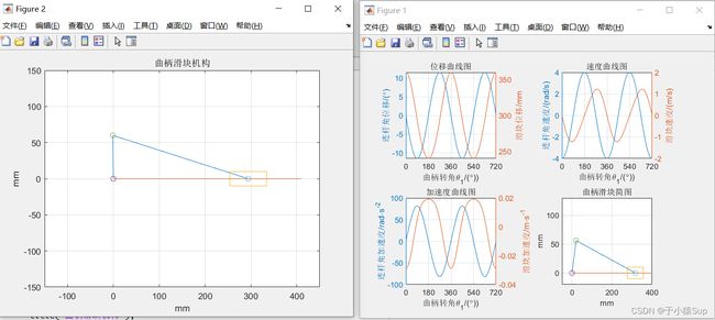
演示:
基于matlab的曲柄滑块仿真运动

