KinectFusion: Real-Time Dense Surface Mapping and Tracking
论文链接:KinectFusion: Real-time dense surface mapping and tracking | IEEE Conference Publication | IEEE Xplore
Abstract
We present a system for accurate real-time mapping of complex and arbitrary indoor scenes in variable lighting conditions, using only a moving low-cost depth camera and commodity graphics hardware. We fuse all of the depth data streamed from a Kinect sensor into a single global implicit surface model of the observed scene in real-time. The current sensor pose is simultaneously obtained by tracking the live depth frame relative to the global model using a coarse-to-fine iterative closest point (ICP) algorithm, which uses all of the observed depth data available. We demonstrate the advantages of tracking against the growing full surface model compared with frame-to-frame tracking, obtaining tracking and mapping results in constant time within room sized scenes with limited drift and high accuracy. We also show both qualitative and quantitative results relating to various aspects of our tracking and mapping system. Modelling of natural scenes, in real-time with only commodity sensor and GPU hardware, promises an exciting step forward in augmented reality (AR), in particular, it allows dense surfaces to be reconstructed in real-time, with a level of detail and robustness beyond any solution yet presented using passive computer vision.
我们展示了一个可以实时精确地在不同光照条件下对复杂和任意的室内环境建图的系统,只用到一个低成本的可移动深度相机和一个商用图形处理硬件。我们将来自Kinect传感器的所有深度数据流融合到观测场景的一个全局隐式表面实时模型中。通过使用粗到精迭代最近点(ICP)算法跟踪相对于全局模型的实时深度图像帧获得当前传感器的姿态。这种算法是的所有观测到的深度信息都利用上了。我们证明了对递增全表面模型的跟踪的优势(与帧到帧的跟踪对比),在室内场景下,在连续时间内获得有限漂移和高精度的跟踪和建图结果。我们还展示了与我们的跟踪和建图系统的各个方面有关的定性和定量结果。仅使用商用传感器和GPU硬件进行自然场景的实时建模,有望在增强现实(AR)领域迈出令人兴奋的一步。它允许实时地重建稠密表面图,具有一定程度的细节和鲁棒性,超过了使用被动计算机视觉提出的任何解决方案。
Keywords: Real-Time, Dense Reconstruction, Tracking, GPU, SLAM, Depth Cameras, Volumetric Representation, AR
1 INTRODUCTION
Real-time infrastructure-free tracking of a handheld camera whilst simultaneously mapping the physical scene in high-detail promises new possibilities for augmented and mixed reality applications
手持相机的实时的无基础设施跟踪,同时绘制高细节的物理场景,为增强现实和混合现实应用提供了新的可能性
In computer vision, research on structure from motion (SFM) and multi-view stereo (MVS) has produced many compelling results, in particular accurate camera tracking and sparse reconstructions (e.g. [10]), and increasingly reconstruction of dense surfaces (e.g. [24]). However, much of this work was not motivated by real time applications
在计算机视觉中,运动结构(SFM)和多视角立体视觉(MVS)的研究已经产生了许多令人瞩目的结果,特别是精确的相机跟踪和稀疏重建(如[10]),以及越来越多的密集表面的重建(如[24])。然而,这项工作的大部分并不是实时应用程序促成的
Research on simultaneous localisation and mapping (SLAM) has focused more on real-time markerless tracking and live scene reconstruction based on the input of a single commodity sensor—a monocular RGB camera. Such ‘monocular SLAM’ systems such as MonoSLAM [8] and the more accurate Parallel Tracking and Mapping (PTAM) system [17] allow researchers to investigate flexible infrastructure- and marker-free AR applications. But while these systems perform real-time mapping, they were optimised for efficient camera tracking, with the sparse point cloud models they produce enabling only rudimentary scene reconstruction.
同时定位与建图(SLAM)的研究更多地集中在基于单一商用传感器(单目RGB摄像机)输入的实时无标记跟踪和现场重建。这种“单目SLAM”系统,如MonoSLAM[8]和更精确的并行跟踪和映射(PTAM)系统[17],允许研究人员研究灵活的基础设施和无标记AR应用。但是,虽然这些系统可以执行实时映射,但它们为高效的摄像机跟踪进行了优化,它们产生的稀疏点云模型只能实现基本的场景重建。
In the past year, systems have begun to emerge that combine PTAM’s handheld camera tracking capability with dense surface MVS-style reconstruction modules, enabling more sophisticated occlusion prediction and surface interaction [19, 26]. Most recently in this line of research, iterative image alignment against dense reconstructions has also been used to replace point features for camera tracking [20]. While this work is very promising for AR, dense scene reconstruction in real-time remains a challenge for passive monocular systems which assume the availability of the right type of camera motion and suitable scene illumination.
在过去的一年中,将PTAM的手持相机跟踪能力与密集表面mvs式重建模块相结合的系统开始出现,实现了更复杂的遮挡预测和表面相互作用[19,26]。最近在这方面的研究中,对于稠密重建的迭代图像对齐方法也被用于替代相机跟踪中的特征点法。尽管这对于AR非常有用,但对于被动单目系统来说,密集场景的实时重建仍然是一个挑战,因为该系统需要具备正确的摄像机运动类型和合适的场景照明。
But while algorithms for estimating camera pose and extracting geometry from images have been evolving at pace, so have the camera technologies themselves. New depth cameras based either on time-of-flight (ToF) or structured light sensing offer dense measurements of depth in an integrated device. With the arrival of Microsoft’s Kinect, such sensing has suddenly reached wide consumer-level accessibility. The opportunities for SLAM and AR with such sensors are obvious, but algorithms to date have not fully leveraged the fidelity and speed of sensing that such devices offer.
在相机位姿预测技术和从多图像中提取几何关系的技术快速发展的同时,相机本身技术也在快速发展。基于飞行时间(ToF)或结构光传感的新型深度相机在集成设备中提供密集的深度测量。随着微软Kinect的问世,这种传感技术突然间普及到消费者层面。有了这样的传感器,SLAM和AR的机遇是显而易见的,但迄今为止,算法还没有充分利用这类设备提供的保真度和传感速度。
In this paper we present a detailed method with analysis of what we believe is the first system which permits real-time, dense volumetric reconstruction of complex room-sized scenes using a hand-held Kinect depth sensor. Users can simply pick up and move a Kinect device to generate a continuously updating, smooth, fully fused 3D surface reconstruction. Using only depth data, the system continuously tracks the 6 degrees-of-freedom (6DOF) pose of the sensor using all of the live data available from the Kinect sensor rather than an abstracted feature subset, and integrates depth measurements into a global dense volumetric model. A key novelty is that tracking, performed at 30Hz frame-rate, is always relative to the fully up-to-date fused dense model, and we demonstrate the advantages this offers. By using only depth data, our system can work in complete darkness mitigating any issues concerning low light conditions, problematic for passive camera [17, 19, 26] and RGB-D based systems [14]. Examples of live reconstructions generated from our system are shown throughout the paper ranging in scale including Figures 1 and 2.
在本文中,我们提出了一种详细的方法,并分析了我们认为是第一个使用手持Kinect深度传感器对复杂房间大小的场景进行实时、密集体积重建的系统。使用者可以简单地拿起并移动Kinect设备去生成一个连续更新的、平滑的、全融合的3D表面重建。该系统仅使用深度数据,利用Kinect传感器提供的所有实时数据(而不是抽象的特征子集)连续跟踪传感器的6自由度(6DOF)姿态,并将深度测量数据集成到全局密集体积模型中。一个关键的创新是在30Hz帧率下执行的跟踪,总是相对于完全最新的融合密集模型,我们展示了这提供的优势。通过只使用深度数据,我们的系统可以在完全黑暗的环境下工作,缓解了关于低光照条件的任何问题,这对于被动相机[17,19,26]和基于RGB-D的系统[14]是有问题的。从我们的系统生成的实时重建示例在整个论文中都有图示,其中包括图1和图2。
The use of highly parallel general purpose GPU (GPGPU) techniques is at the core of all of our design decisions, allowing both tracking and mapping to perform at the frame-rate of the Kinect sensor (and even at higher rates) and in constant time. Qualitative and quantitative results in this paper demonstrate various aspects of the tracking and mapping system performance
使用高度并行的通用GPU (GPGPU)技术是我们所有设计决策的核心使得追踪和建图能在Kinect传感器的帧率下并持续不断地运行(甚至在更高的速率)。本文的定性和定量结果展示了跟踪与测绘系统各方面的性能。
We believe that the resulting system will become an enabler for many AR and interaction scenarios. In particular, the high quality, real time, reconstruction and tracking will enable a fuller physically predictive interaction between the virtual and the real scene, as well as providing the high quality occlusion handling required for complex mixed reality geometry.
我们相信,最终的系统将成为许多AR和交互场景的推动者。特别是,高质量、实时、重建和跟踪将使得虚拟和真实场景之间有了更全面的物理预测及交互,以及提供高质量的遮挡处理所需的复杂混合现实几何技术。
2 BACKGROUND
2.1 The Kinect Sensor
Kinect is a new and widely-available commodity sensor platform that incorporates a structured light based depth sensor. Using an on-board ASIC a 11-bit 640x480 depth map is generated at 30Hz.
Kinect是一个新的、广泛使用的商品传感器平台,它包含一个基于结构光的深度传感器。使用板载专用集成电路,在30Hz频率下生成11位640x480深度图。
While the quality of this depth map is generally remarkable given the cost of the device, a number of challenges remain. In particular, the depth images contain numerous ‘holes’ where no structured light depth reading was possible. This can be due to certain materials or scene structures which do not reflect infra-red (IR) light, very thin structures or surfaces at glancing incidence angles. When moved fast the device will also experience motion blur (like any camera) and this can also lead to missing data.
考虑到设备的成本,这种深度地图的质量通常是显著的,但仍然存在一些挑战。特别是,深度图像包含许多“洞”,没有结构化的光深度的读取。这可能是由于某些材料或场景结构不反射红外线(IR)光,或者非常薄的结构或表面。当移动速度很快时,设备还会出现运动模糊(就像任何相机一样),这也会导致数据丢失。
Our system takes the real-time stream of noisy depth maps from Kinect and performs real-time dense SLAM, producing a consistent 3D scene model incrementally while simultaneously tracking the sensor’s agile motion using all of the depth data in each frame. In the following sections we review important related work on SLAM, dense tracking, surface representations and previous work on joint tracking and modelling with active depth sensors.
我们的系统从Kinect获取实时的噪声深度图流,并执行实时稠密SLAM,逐步生成连续的3D场景模型,同时使用每帧中的所有深度数据跟踪传感器敏捷的运动。在接下来的章节中,我们将回顾与SLAM相关的重要工作如稠密跟踪、曲面表示,以及使用主动深度传感器进行联合跟踪和建模的前期工作。
2.2 Drift-Free SLAM for AR
Most SLAM algorithms must be capable of producing self-consistent scene maps and performing drift-free sensor tracking in a sequential, real-time fashion. Early SFM algorithms capable of dealing with a large number of images had either tracked camera motion incrementally, accumulating drift [2], or required off-line optimisation [10] to close loops. The first ‘monocular SLAM’ system capable of producing a globally consistent maps in real-time with a handheld camera was based on probabilistic filtering of a joint state consisting of camera and scene feature position estimates [8]. This system was targeted at small-scale workspaces compatible with some AR applications, but was in fact limited to these due the high computational cost of filtering a large state vector containing the many features that would be needed to map larger areas. Even in small spaces, this issue meant that the tracking accuracy which could practically be achieved in real-time was relatively poor due to the sparse feature maps built.
大多数SLAM算法必须能够产生一致性的场景地图,传感器连续的、实时的跟踪不产生漂移。早期能够处理大量图像的SFM算法要么是增量式地跟踪相机运动,会积累漂移[2],要么需要通过离线优化[10]来进行闭环 。第一个“单目SLAM”系统能够通过手持摄像机实时生成全局一致的地图,该系统基于由摄像机和场景特征位置估计[8]组成的联合状态的概率滤波。该系统的目标与一些AR应用程序相同,都针对于小规模工作空间,但实际上仅限于这些,因为对包含丰富特征的大型状态向量(需要对更大区域进行建图)进行滤波的高计算成本。即便是在小空间内,这个问题意味着实时的跟踪精度也是相对较低的,因为构建的特征点地图的稀疏性。
Later, it was discovered to be practically advantageous to abandon the propagation of a full probabilistic state and instead to run two procedures in alternation or in parallel: tracking, estimating the pose of the sensor on the assumption that the current scene model is perfectly accurate; and mapping, improving and expanding the map using a form of global optimisation. This approach was pioneered by the PTAM system [17] which demonstrated quality real-time SLAM with a monocular camera in small workspaces. PTAM’s mapping component is nothing but bundle adjustment, the classical least-squares solution to camera and feature optimisation, but implemented judiciously over an automatically selected set of spatially-distributed keyframes and running repeatedly as often as computing resources will allow. PTAM’s highly engineered live tracking component runs in parallel at frame-rate, and performs feature matching and robust n-point pose estimation. Compared to filters, this architecture means that an order of magnitude more scene features could be packed into the map [25], and the result was real-time accuracy now comparable to results in off-line reconstruction.
后来,人们发现放弃全概率状态的传播,而是交替或并行地运行两个程序是有利的:跟踪和估计传感器的姿态(假设当前场景模型是完全准确的);建图,改进和扩大地图使用一种全局优化的形式。该方法由PTAM系统[17]首创,该系统在小型工作空间中使用单目摄像机实现了高质量的实时SLAM。PTAM的建图组件不过是一个BA-一个经典的对相机位姿和特征进行优化地最小二乘解决方案,但PTAM很明智的地方在于它自动选择一组空间分布的关键帧并只要计算资源允许就重复运行。PTAM高度工程化的实时跟踪组件以帧率速度并行地运行,并执行特征匹配和鲁棒的n点姿态估计。与滤波器相比,这种结构意味着更多的场景特征可以被打包进地图中。结果是虽是实时的精度但现在可以与离线重建的结果相媲美。
But PTAM’s principle of splitting tracking and mapping can be taken much further, since it allows a flexible choice of the components used for each of those processes. PTAM, as a feature-based system, achieves excellent accuracy for camera tracking in previously unknown scenes, but the sparse point map it generates is still not useful for much beyond providing localisation landmarks. A number of recent approaches have concentrated on this point, and have demonstrated live reconstruction of dense geometry using multi-view stereo techniques while relying on sparse models for estimating the sensor motion. [19], using a monocular camera and dense variational optical flow matching between selected frames, were able to reconstruct a patchwork of depth maps to form a dense scene model live; but relied on camera pose estimates coming from PTAM. [26] presented another system with many of the same ideas but further demonstrated near-real-time depth map creation.
但是PTAM的分离跟踪和建图的原则可以进一步发展,因为它允许灵活地选择用于每个过程的组件。作为一种基于特征的系统,PTAM在未知的场景中实现了出色的相机跟踪精度,但它生成的稀疏点地图除了提供定位地标外,仍然没有太多用处。许多最近的方法都集中在这一点上,并证明了使用多视图几何技术对稠密构造的实时重建,同时依赖稀疏模型来估计传感器运动。利用单目相机和dense variational optical flow对所选帧之间进行匹配,能够重建一个拼接的深度图,形成稠密的现场场景模型;而是依赖于PTAM的摄像机姿态估计。呈现了另一个具有许多相同理念的系统,但进一步演示了接近实时的深度地图创建。
2.3 Dense Tracking and Mapping by Scan Alignment-即ICP
Alongside mapping and tracking work using passive cameras, a line of research has continued using active laser and depth imaging sensors in the fields of robotics and graphics. These methods have had at their core the alignment of multiple scans by minimising distance measures between all of the data in each rather than feature extraction and matching.
除了使用被动相机进行测绘和跟踪工作外,在机器人和图形领域还继续使用主动激光和深度成像传感器进行研究。这些方法的核心是通过最小化每次扫描中所有数据之间的距离度量来对齐多次扫描,而不是特征提取和匹配。
Some of the first useful algorithms for obtaining both full 6DOF scan alignment (robot pose) and surface reconstruction (environment mapping) were developed in the graphics domain for the detailed reconstruction of individual objects. The most important class of algorithms have been based on the ICP concept introduced in [3] which poses data alignment as a nonlinear optimisation problem in which correspondences between scans are approximated using the closest pairs of points found between scans at the previous iteration. Distance metrics have been investigated including the point-plane metric [5] which was shown to improve convergence rates and is the preferred algorithm when surface normal measurements are available. The process of obtaining the closest point correspondences is expensive; a drastic speed up introduced by the projective data association algorithm [4] is available for depth data obtained in projective image form where measurements are given as a function of pixel location. A number of ICP variants perform early iterations on a subset of possibly corresponding points or operate within a coarse-to-fine scheme [31], speeding up both the data association and final pose optimisation.
用于获得全部6自由度扫描对齐(机器人姿态)和表面重建(环境映射)的首批实用算法是在图形领域开发的,用于单个对象的细节重建。最重要的一类算法是基于[3]中引入的ICP概念,该概念将数据对齐作为一个非线性优化问题,其中扫描之间的对应关系是使用前一次迭代中扫描之间找到的最接近的点对来近似。距离度量已经进行了研究,包括点平面度量[5],它被证明可以提高收敛速度,当表面正常测量可用时,是首选的算法。获取有联系的最近点的过程是昂贵的;通过投影数据关联算法[4]可以获得以投影图像形式获得的深度数据,其中测量值作为像素位置的函数给出。许多ICP变体在可能对应的点子集上执行早期迭代,或在粗到细的方案[31]中操作,加快数据关联和最终姿态优化。
Some SLAM algorithms have also made use of depth data alignment and ICP (often referred to in robotics as scan matching), originally in 2D using laser range-finder sensors, to produce effective robot localisation algorithms which can also autonomously map detailed space occupancy in large areas [12]. ICP is used to estimate relative robot motion between consecutive poses, which together with loop closure detection and correction can produce large scale metrically consistent maps.
一些SLAM算法还利用了深度数据对齐和ICP(通常在机器人中称为扫描匹配),最初在2D中使用激光测距传感器,以产生有效的机器人定位算法,该算法还可以自主绘制大范围[12]的详细空间占用情况。采用ICP估计机器人连续位姿之间的相对运动,结合闭环检测和修正,可以生成大比尺尺度的度量一致的地图。
2.4 Dense Scene Representations
Dense depth measurements from active sensors, once aligned, can be used to produce fused representations of space which are better than simply overlapping scans. Occupancy mapping has been popular in robotics, and represents space using a grid of cells, within each of which a probability of occupancy is accumulated via Bayesian updates every time a new range scan provides an informative observation [9]. Such non-parametric environment models provide vital free space information together with arbitrary genus surface representation with orientation information, important when physical interaction predictions are required (as is the case in robotics and augmented reality)
来自主动传感器的密集深度测量,一旦对齐,可以用来产生融合的空间表示,这比简单的重叠扫描更好。Occupancy mapping在机器人技术中很受欢迎,它使用单元格网格来表示空间,在每个单元格中,每当新的范围扫描提供一个有信息的观察[9]时,通过贝叶斯更新积累占用的概率。这种非参数环境模型提供了至关重要的自由空间信息,以及带有方向信息的任意曲面表示,在需要进行物理交互预测时非常重要(如机器人和增强现实中的情况)。
A related non-parametric representation used in graphics is the signed distance function (SDF) introduced in [7] for the purpose of fusing partial depth scans while mitigating problems related to mesh-based reconstruction algorithms. The SDF represents surface interfaces as zeros, free space as positive values that increase with distance from the nearest surface, and (possibly) occupied space with a similarly negative value. It has been shown in [15], that Bayesian probabilistic inference of the optimal surface reconstruction, under a simple Gaussian noise model on the depth measurements with a surface visibility predicate that every surface point is visible from all sensor viewpoints, results in a simple algorithm of averaging weighted signed distance function into the global frame. In practice the result is only locally true due to surface occlusions and truncation of the SDF as detailed in [7] is required to avoid surfaces interfering. For higher fidelity reconstructions, at the cost of extra computation, when depth maps are contaminated with heavy-tailed noise or outliers, the more recent work of [30] uses the more robust L1 norm on the truncated SDF data term together with a total variation regularisation to obtain globally optimal surface reconstructions.
在图形中使用的一个相关的非参数表示是[7]中引入的符号距离函数(SDF),目的是融合部分深度扫描,同时减轻基于网格的重建算法的问题。SDF表示表面界面为零,自由空间为正值,随着距离最近的表面的距离增加,并且(可能)占用的空间有一个类似的负值。[15]中已经表明,在简单的高斯噪声模型下,对深度测量的最优表面重建的贝叶斯概率推断与表面可视性谓词,每个表面点从所有传感器视点可见,结果是一个简单的算法平均加权符号距离函数到全局框架。在实践中,由于如[7]中详细描述的SDF中的表面遮挡和截断,结果只在局部是正确的,以避免表面干扰。当深度图被重尾噪声或异常值污染时,为了获得更高的保真度重构,最近的工作[30]以额外的计算为代价,在截断的SDF数据项上使用更稳健的L1范数,并结合全变分正则化来获得全局最优的表面重构。
An advantage of the SDF over basic probabilistic occupancy grids is that the surface interface is readily extractable as the zero crossings of the function in contrast to seeking the modes of a probability distribution in the occupancy grid. This was noted in [7] and has an important consequence in our work where we utilise the full currently reconstructed surface model to obtain a prediction for use in live sensor pose estimation. Given a SDF representation two main approaches to obtaining a view (rendering) of the surface exist, and have been extensively studied within the graphics community. One option is to extract the connected surfaces using a marching cubes type algorithm [18], followed by a standard rasterising rendering pipeline. Alternatively the surface can be directly raycast, avoiding the need to visit areas of the function that are outside the desired view frustum. This is attractive due to the scene complexity-independent nature of the algorithm [21], a factor that is becoming increasingly important as the requirement for real-time photo-realistic rendering increases [1].
与基本概率占用网格相比,SDF的一个优点是,与在占用网格中计算概率分布的模型相比,表面界面很容易提取为函数的零交叉点。这在[7]中得到了注意,并且在我们的工作中有一个重要的结果,我们利用完整的当前重建表面模型来获得用于实时传感器位姿估计的预测。给定一个SDF表示,有两种主要的方法来获得表面的视图(渲染),并在图形学领域中进行了广泛的研究。一种选择是使用移动立方体类型算法[18]提取连接的曲面,然后使用标准的栅格化渲染管道。另外一种是,表面可以directly raycast,避免了观察视图截锥之外功能区域的需求。这是有吸引力的,因为算法[21]的场景独立复杂性的性质,这是一个越来越重要的因素,随着实时真实感渲染的需求的增加[1]。
2.5 Dense SLAM with Active Depth Sensing
Rusinkiewicz et al. [23] combined a real-time frame-to-frame ICP implementation using the point-plane metric and projective data association together with a point based occupancy averaging and splat rendering of the aligned scans to demonstrate the first live reconstruction results of small models. In their system a user manoeuvres an object by hand and sees a continuously-updated model as the object is scanned. The system was able to fuse depth images from the range finder for rendering purposes at rates up to 10Hz. The restrictive non mobile range sensor prototype and lack of global pose optimisation to reduce drift prevented them from using the system for reconstructing larger scenes. The final models were optimised off-line using [7]. They conclude that with substantial increases in computational power, it might be possible to instead perform live volumetric SDF fusion. More notably, they suggest the possibility of using such an accumulated global reconstruction for resolving ambiguities that occur with frame-to-frame ICP. With the advent of GPU hardware and our efficient implementation thereon we are able to achieve both these goals in our system.
Rusinkiewicz等人[23]将一种实时帧到帧的ICP实现(使用点平面度量)和投影数据关联的方法结合起来,以及对齐扫描的基于点的占用平均和splat渲染,展示了小模型的第一个实时重建结果。在他们的系统中,用户手动操纵一个物体,并在物体被扫描时看到一个不断更新的模型。该系统能够融合来自测距仪的深度图像,以高达10Hz的速率进行渲染。受限的非便携性距离传感器原型和缺乏减少漂移的全局位姿优化,使他们无法使用该系统重建更大的场景。使用[7]离线优化最终模型。他们得出的结论是,随着计算能力的大幅提高,有可能实现实时体积SDF融合。更值得注意的是,他们建议有可能使用这种累积的全局重建来解决帧对帧ICP产生的歧义。随着GPU硬件的出现和我们在其上的高效实现,我们能够在我们的系统中实现这两个目标(体积SDF融合和解决帧对帧ICP的歧义)。
The introduction of commercially available depth cameras has inspired other related real-time 3D reconstruction. For example, the work of Weise et al. [28] produces high quality scans using a fixed ToF sensor and moving object, whereas Cui et al. [6] demonstrate a moving handheld ToF object scanner. These systems are motivated by small scale high quality scanning of objects. Whilst our system supports such reconstructions, the main focus of our work is on reconstruction of larger scale scenes from higher speed camera motions.
商用深度相机的问世激发了其他相关实时3D重建的灵感,例如,Weise等人[28]的工作使用固定的ToF传感器和移动物体产生高质量的扫描,而Cui等人[6]演示了移动手持ToF物体扫描仪。这些系统的动机来自于对物体的小范围高质量扫描。虽然我们的系统支持这样的重建,但我们工作的主要重点是从高速相机运动重建更大规模的场景。
More recently, SLAM work has focused on large scale reconstruction (mapping) including an impressive recent 3D version of the occupancy mapping approach, relying on 3D laser range-finder data and using octrees to enable scaling to large volumes is the Octomap algorithm [29]. RGB-D approaches that combine depth representations are also beginning to appear with the advent of the affordable Microsoft Kinect RGB-D sensor. [14] estimated the live 3D motion of the sensor (1 – 2Hz update) by obtaining relative frame alignment via ICP alignment between depth scans initialised by RGB feature matching. Global consistency was achieved using a pose graph optimisation by using loop closures detected using RGB feature correspondences. This system, while impressive, was targeted at large scale building mapping; the tracking front end was not designed to provide real-time performance needed for useful augmented reality; and the dense modelling (based on a surface patch representation) provides a less refined reconstruction than can be achieved by using a full global fusion approach.
最近,SLAM的工作集中在大规模重建(映射),包括最近令人印象深刻的占用映射方法的3D版本,依赖于3D激光测距仪数据,并使用八叉树实现大容量缩放,这是Octomap algorithm [29]。结合深度表现的RGB-D方法也随着廉价的微软Kinect RGB-D传感器的出现而开始出现。[14]通过RGB特征匹配初始化的深度扫描之间的ICP比对获得相对帧对齐,从而估计传感器的实时3D运动(1 - 2Hz更新)。全局一致性通过使用RGB特征的闭环检测来实现位姿图优化。这个系统虽然令人印象深刻,但它的目标是大规模的建筑地图;跟踪前端的设计不能提供有用的增强现实所需的实时性能; 而稠密建模(基于表面斑块表示)提供的重建不如使用全全局融合方法所能实现的精细。
3 METHOD

We now describe the components that make up our system. Figure 3 provides an overview of our whole method in block form. It is comprised of the following four components:
现在我们描述组成系统的组件。图3提供了整个方法的概览。它由下列四个部分组成:
Surface measurement: A pre-processing stage, where a dense vertex map and normal map pyramid are generated from the raw depth measurements obtained from the Kinect device.
表面测量:预处理阶段,从Kinect设备获得的原始深度测量结果生成密集顶点图和法线地图金字塔。
Surface reconstruction update: The global scene fusion process, where given the pose determined by tracking the depth data from a new sensor frame, the surface measurement is integrated into the scene model maintained with a volumetric, truncated signed distance function (TSDF) representation.
表面重建更新:全局场景融合过程,通过跟踪来自传感器的新的一帧的深度数据确定姿态,表面测量被集成到场景模型中,用体积、截断符号距离函数(TSDF)表示保持。
Surface prediction: Unlike frame-to-frame pose estimation as performed in [15], we close the loop between mapping and localisation by tracking the live depth frame against the globally fused model. This is performed by raycasting the signed distance function into the estimated frame to provide a dense surface prediction against which the live depth map is aligned.
表面预测:与[15]中执行的帧到帧的姿态估计不同,我们通过对全局融合模型跟踪实时深度帧来关闭建图和定位之间的循环。这是通过将有符号的距离函数投射到估计帧中来执行的,以提供一个密集的表面预测,实时深度图与之对齐。
Sensor pose estimation: Live sensor tracking is achieved using a multi-scale ICP alignment between the predicted surface and current sensor measurement. Our GPU based implementation uses all the available data at frame-rate.
传感器姿态估计:实时传感器跟踪是通过多尺度ICP比对预测表面和电流传感器测量实现的。我们基于GPU的实现使用所有可用的帧率数据。
3.1 Preliminaries-先验知识
We represent the live 6DOF camera pose estimated for a frame at time k by a rigid body transformation matrix:
我们用刚体变换矩阵表示k时刻一帧估计的实时6DOF相机姿态:

where the Euclidean group SE3 := {R,t | R ∈ SO3 ,t ∈ R3}. This maps the camera coordinate frame at time k into the global frame g, such that a point pk ∈ R3 in the camera frame is transferred into the global co-ordinate frame via pg = Tg,k*pk
其中欧式群SE3 := {R,t | R ∈ SO3 ,t ∈ R3}.这个变换矩阵将时刻k处的相机坐标系转化到全局坐标系g下,比如说相机坐标系下的pk转化为全局坐标系通过式子pg = Tg,k*pk进行转化
We will also use a single constant camera calibration matrix K that transforms points on the sensor plane into image pixels. The function q = π(p) performs perspective projection of p ∈ R3 = (x,y,z)^T including dehomogenisation to obtain q ∈ R2 = (x/z, y/z)^T. We will also use a dot notation to denote homogeneous vectors 
我们还将使用一个恒定的摄像机校准矩阵K,它将传感器平面上的点(十四讲中的归一化平面)转换为图像像素。此外,方程q = π(p)是对三维坐标p ∈ R3的投影得到归一化坐标q ∈ R2 = (x/z, y/z)^T。我们也可以用点标记表示齐次向量
3.2 Surface Measurement
At time k a measurement comprises a raw depth map Rk which provides calibrated depth measurements Rk(u) ∈ R at each image pixel u = (u, v)^T in the image domain ![]() such that pk =
such that pk = ![]() is a metric point measurement in the sensor frame of reference k. We apply a bilateral filter [27] to the raw depth map to obtain a discontinuity preserved depth map with reduced noise Dk,
is a metric point measurement in the sensor frame of reference k. We apply a bilateral filter [27] to the raw depth map to obtain a discontinuity preserved depth map with reduced noise Dk,
时刻k时的测量由为每一个像素坐标u = (u, v)^T提供的深度 Rk(u) ∈ R组成的原始深度值图构成,因此时刻k处的某像素坐标对应的相机坐标系的坐标为 pk = ![]() 。我们将双边滤波器[27]应用于原始深度图,可获得一个具有降低噪声的不连续深度图Dk。
。我们将双边滤波器[27]应用于原始深度图,可获得一个具有降低噪声的不连续深度图Dk。

where  and Wp is a normalizing constant. We back-project the filtered depth values into the sensor’s frame of reference to obtain a vertex map Vk ,
其中和Wp是标准化常量。我们将经过滤波的深度值反投影到相机坐标系获得顶点图Vk

Since each frame from the depth sensor is a surface measurement on a regular grid, we compute, using a cross product between neigh-bouring map vertices, the corresponding normal vectors,
由于来自深度传感器的每一帧都是规则网格上的表面测量,我们使用相邻贴图顶点的叉积来计算对应的法向量,

where![]()
We also define a vertex validity mask: Mk(u) → 1 for each pixel where a depth measurement transforms to a valid vertex; otherwise if a depth measurement is missing Mk(u)→ 0. The bilateral filtered version of the depth map greatly increases the quality of the normal maps produced, improving the data association required in tracking described in Section 3.5.
我们还定义了一个顶点有效性掩码:Mk(u)→1表示深度测量每个像素转换为顶点是有效的;否则如果深度测量缺少则Mk(u)→0。经双边滤波的深度图大大提高了生成法线图的质量,改善了3.5节描述的跟踪所需的数据关联
We compute an L = 3 level multi-scale representation of the surface measurement in the form of a vertex and normal map pyramid. First a depth map pyramid  is computed. Setting the bottom depth map pyramid level equal to the original bilateral filtered depth map, the sub-sampled version
 ![]() is computed from
is computed from ![]() by block averaging followed by sub-sampling to half the resolution. Depth values are used in the average only if they are within
by block averaging followed by sub-sampling to half the resolution. Depth values are used in the average only if they are within ![]() of the central pixel to ensure smoothing does not occur over depth boundaries. Subsequently each level in a vertex and normal map pyramid
of the central pixel to ensure smoothing does not occur over depth boundaries. Subsequently each level in a vertex and normal map pyramid ![]() is computed with Equations 3 and 4 using the corresponding depth map level. We note that given the camera to global co-ordinate frame transform Tg,k associated with the surface measurement, the global frame vertex is
is computed with Equations 3 and 4 using the corresponding depth map level. We note that given the camera to global co-ordinate frame transform Tg,k associated with the surface measurement, the global frame vertex is  and the equivalent mapping of normal vectors into the global frame is
我们计算一个以顶点和法线地图金字塔的形式的L = 3级的表面测量的多尺度表征。首先计算一个深度图金字塔。将金字塔的底层设为原始的双边滤波深度图,降采样版本![]() 通过
通过![]() 经块平均方法计算使得分辨率降低一半。深度值仅在中心像素的
经块平均方法计算使得分辨率降低一半。深度值仅在中心像素的![]() 范围内时才会被使用在均值算法中,以确保滤波操作不会发生在深度图边界外。随后,顶点和法线映射金字塔中的每一层的
范围内时才会被使用在均值算法中,以确保滤波操作不会发生在深度图边界外。随后,顶点和法线映射金字塔中的每一层的![]() 都使用该层对应的深度用公式3和4来计算。我们注意到,给定相机坐标系到全局坐标系变换Tg,k与表面测量有关,全局坐标系下的vertex是,法向量到全局坐标系的等价映射是
都使用该层对应的深度用公式3和4来计算。我们注意到,给定相机坐标系到全局坐标系变换Tg,k与表面测量有关,全局坐标系下的vertex是,法向量到全局坐标系的等价映射是
3.3 Mapping as Surface Reconstruction
Each consecutive depth frame, with an associated live camera pose estimate, is fused incrementally into one single 3D reconstruction using the volumetric truncated signed distance function (TSDF) [7]. In a true signed distance function, the value corresponds to the signed distance to the closest zero crossing (the surface interface), taking on positive and increasing values moving from the visible surface into free space, and negative and decreasing values on the non-visible side. The result of averaging the SDF’s of multiple 3D point clouds (or surface measurements) that are aligned into a global frame is a global surface fusion.
利用体积的截断符号距离函数(TSDF)[7]将每个连续的深度帧,连同相关的实时相机的姿态估计,渐进融合到单个3D重建中。在一个真正的有符号距离函数中,该值对应于到最近的零交叉点(表层界面)的有符号距离,从可见表面移动到自由空间的值呈现为正的和递增的,而在不可见的一面则是负的和递减的。将多个三维点云(或表面测量数据)的SDF平均到一个全局框架中,得到的结果就是全局表面融合。
An example given in Figure 4 demonstrates how the TSDF allows us to represent arbitrary genus surfaces as zero crossings within the volume. We will denote the global TSDF that contains a fusion of the registered depth measurements from frames 1... k as Sk(p) where p ∈ R3 is a global frame point in the 3D volume to be reconstructed. A discretization of the TSDF with a specified resolution is stored in global GPU memory where all processing will reside. From here on we assume a fixed bijective mapping between voxel/memory elements and the continuous TSDF representation and will refer only to the continuous TSDF S. Two components are stored at each location of the TSDF: the current truncated signed distance value Fk(p) and a weight Wk(p),
图4中给出的一个示例演示了TSDF如何允许我们将任意种类的曲面表示为体积内的零交叉点。我们将表示全局TSDF,其中包含从帧1到帧k中的深度测量(表示为Sk(p))的融合,其中p∈R3是待重构三维物体中的全局坐标系的点。具有指定分辨率的TSDF离散化存储在全局GPU内存中,所有处理都驻留在该内存中。从这里开始,我们假设体素/记忆元素和连续的TSDF表示之间有一个固定的双射映射,我们只指连续的TSDF S,TSDF的每个位置存储两个分量:当前截断的符号距离值Fk(p)和权重Wk(p),

A dense surface measurement (such as the raw depth map Rk ) provides two important constraints on the surface being reconstructed. First, assuming we can truncate the uncertainty of a depth measurement such that the true value lies within ±µ of the measured value, then for a distance r from the camera center along each depth map ray, r < (λRk(u) − µ) is a measurement of free space (here  scales the measurement along the pixel ray). Second, we assume that no surface information is obtained in the reconstruction volume at r > (λRk(u) + µ) along the camera ray. Therefore the SDF need only represent the region of uncertainty where the surface measurement exists |r −λRk(u)| ≤ µ. A TSDF allows the asymmetry between free space, uncertain measurement and unknown areas to be represented. Points that are within visible space at distance greater than µ from the nearest surface interface are truncated to a maximum distance µ. Non-visible points farther than µ from the surface are not measured. Otherwise the SDF represents the distance to the nearest surface point.
密集表面测量(如原始深度图Rk)对被重建的表面提供了两个重要的约束。第一,假设我们可以截断深度测量的不确定度,使真值位于测量值的±µ内,那么对于沿着每个深度图射线距离相机中心r的距离,r < (λRk (u)−µ)是自由空间的测量(这里 是沿像素射线的测量缩放值)。第二,假设重构体沿相机射线方向r > (λRk(u) +µ)处没有表面信息。因此SDF只需要表征存在不确定度的区域|r−λRk(u)|≤µ。TSDF可以表示自由空间,不确定测量和未知区域之间的不对称性。距离最近的表面大于 µ 的可见空间内的点被截断。距离表面远于µ的非可见点不去测量,否则别的情况下,SDF表示到最近的表面点的距离。
Although efficient algorithms exist for computing the true discrete SDF for a given set of point measurements (complexity is linear in the the number of voxels) [22], sophisticated implementations are required to achieve top performance on GPU hardware, without which real-time computation is not possible for a reasonable size volume. Instead, we use a projective truncated signed distance function that is readily computed and trivially parallelisable. For a raw depth map Rk with a known pose Tg,k , its global frame projective TSDF ![]() at a point p in the global frame g is computed as,
at a point p in the global frame g is computed as,
尽管存在有效的算法来计算给定点测量集的真正离散SDF(复杂度与体素数量呈线性关系),但是复杂的实现是需要GPU硬件的完美表现,如果没有GPU硬件对于那怕合理大小的实时计算都是不可实现的。相反,我们使用一个投影截断符号距离函数,这是容易计算的和具有并行性的。对于一个已知姿态Tg,k的原始深度图Rk,其全局坐标系g中p点处的全局框架投影TSDF-![]() 计算为:
计算为:

We use a nearest neighbour lookup  instead of interpolating the depth value, to prevent smearing of measurements at depth discontinuities. 1/λ converts the ray distance to p to a depth (we found no considerable difference in using SDF values computed using distances along the ray or along the optical axis). Ψ performs the SDF truncation. The truncation function is scaled to ensure that a surface measurement (zero crossing in the SDF) is represented by at least one non truncated voxel value in the discretised volume either side of the surface. Also, the support is increased linearly with distance from the sensor center to support correct representation of noisier measurements. The associated weight
  is proportional to cos(θ)/Rk(x), where θ is the angle between the associated pixel ray direction and the surface normal measurement in the local frame.
我们使用最近邻查找而不是插值深度值,防止在深度不连续处的测量结果被涂抹。1/λ将至p的射线距离转换为深度(我们发现使用沿射线或沿光轴的距离计算的SDF值没有相当大的差异)。Ψ执行SDF截断。对截断函数进行了缩放,以保证曲面的测量(SDF中的零交叉)是由表面两侧的离散体素中至少一个未被截断的体素值表示。此外,随着距离传感器中心的距离的支持度的线性增加,以支持噪声测量的正确表示。相关权重 与cos(θ)/Rk(x)成正比,式中θ为相关像素射线方向与局部帧内表面法线测量值之间的夹角。
The projective TSDF measurement is only correct exactly at the surface FRk (p) = 0 or if there is only a single point measurement in isolation. When a surface is present the closest point along a ray could be another surface point not on the ray associated with the pixel in Equation 8. It has been shown that for points close to the surface, a correction can be applied by scaling the SDF by cos(θ) [11]. However, we have found that approximation within the truncation region for 100s or more fused TSDFs from multiple viewpoints (as performed here) converges towards an SDF with a pseudo-Euclidean metric that does not hinder mapping and tracking performance.
投射TSDF测量只有在表面FRk (p) = 0或只有单独的单点测量时才准确。当一个曲面出现时,沿着一条射线最近的点可以是另一个曲面点,不在方程8中像素相关的射线上。结果表明,对于接近表面的点,可以通过用cos(θ)[11]缩放SDF来进行修正。然而,我们已经发现,在截断区域内对100个或更多来自多个视点的融合TSDF(在这里执行)的近似收敛到一个具有伪欧几里得度量的SDF,这不会影响映射和跟踪性能。
The global fusion of all depth maps in the volume is formed by the weighted average of all individual TSDFs computed for each depth map, which can be seen as de-noising the global TSDF from multiple noisy TSDF measurements. Under an L2 norm the denoised (fused) surface results as the zero-crossings of the point-wise SDF F minimising:
体积中所有深度图的全局融合是由每个深度图计算的所有单个TSDF的加权平均值形成的,这可以被视为从多个有噪声的TSDF测量中去噪的全局TSDF。在L2范数下,去噪(融合)表面的结果为逐点SDF F最小化的零交叉点:

Given that the focus of our work is on real-time sensor tracking and surface reconstruction we must maintain interactive frame-rates. (For a 640x480 depth stream at 30fps the equivalent of over 9 million new point measurements are made per second). Storing a weight Wk(p) with each value allows an important aspect of the global minimum of the convex L2 de-noising metric to be exploited for real-time fusion; that the solution can be obtained incrementally as more data terms are added using a simple weighted running average [7], defined point-wise :
:
考虑到我们的工作重点是实时传感器跟踪和表面重建,我们必须保持交互帧率(对于30fps的640x480深度的流,相当于每秒进行900多万个新的点测量)。为每个值存储一个权重Wk(p),可以利用凸L2去噪度量的全局最小值这一个重要方面进行实时融合;随着更多的数据项的添加,可以使用简单的加权运行平均值[7],定义点式 来递增地获得解决方案:
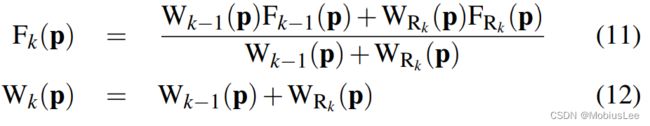
No update on the global TSDF is performed for values resulting from unmeasurable regions specified in Equation 9. While Wk(p) provides weighting of the TSDF proportional to the uncertainty of surface measurement, we have also found that in practice simply letting WRk (p) = 1, resulting in a simple average, provides good results. Moreover, by truncating the updated weight over some value Wη ,
对于公式9中指定的不可测量区域所产生的值,没有对全局TSDF进行更新。Wk(p)提供了与表面测量不确定度成比例的TSDF的权重,我们还发现,在实践中,简单地让WRk (p) = 1,得到一个简单的平均值,可以提供很好的结果。此外,通过在某个值Wη上截断更新的权值,

a moving average surface reconstruction can be obtained enabling reconstruction in scenes with dynamic object motion.
可以得到一个移动平均表面重建,可实现物体运动场景的重建。
Although a large number of voxels can be visited that will not project into the current image, the simplicity of the kernel means operation time is memory, not computation, bound and with current GPU hardware over 65 gigavoxels/second (≈ 2ms per full volume update for a 5123 voxel reconstruction) can be updated. We use 16 bits per component in S(p), although experimentally we have verified that as few as 6 bits are required for the SDF value. Finally, we note that the raw depth measurements are used for TSDF fusion rather than the bilateral filtered version used in the tracking component, described later in section 3.5. The early filtering removes desired high frequency structure and noise alike which would reduce the ability to reconstruct finer scale structures.
虽然可以访问大量不会投射到当前图像的体素,内核的简单性意味着操作时间等于内存,不计算,绑定和当前GPU硬件超过65gigavoxels /秒(5123体素重建的完整卷更新≈2ms)可以更新。我们在S(p)中每个组件使用16位,尽管我们已经通过实验验证了SDF值只需要6位。最后,我们注意到原始深度测量用于TSDF融合,而不是跟踪组件中使用的双边过滤版本,后面的3.5节将对此进行描述。早期滤波去除所需的高频结构和噪声,这将降低重构更细尺度结构的能力。
3.4 Surface Prediction from Ray Casting the TSDF
With the most up-to-date reconstruction available comes the ability to compute a dense surface prediction by rendering the surface encoded in the zero level set Fk = 0 into a virtual camera with the current estimate Tg,k . The surface prediction is stored as a vertex and normal map in frame of reference k and is used in the subsequent camera pose estimation step.
随着最新的重建可用来计算密集表面预测的能力,将编码在零水平集Fk = 0的表面渲染到一个虚拟相机与当前估计Tg,k。表面预测存储为参考k的顶点和法线映射框架,用于后续的相机姿态估计步骤。
As we have a dense surface reconstruction in the form of a global SDF, a per pixel raycast can be performed [21]. Each pixel’s corresponding ray,  , is marched starting from the minimum depth for the pixel and stopping when a zero crossing (+ve to −ve for a visible surface) is found indicating the surface interface. Marching also stops if a −ve to +ve back face is found, or ultimately when exiting the working volume, both resulting in non surface measurement at the pixel u.
由于我们以全局SDF的形式有一个密集的表面重建,每个像素的光线投射都可以执行[21]。每个像素对应的光线,从像素的最小深度开始行进,并在零交叉点时停止(+ve到- ve表示可见表面)指示表面界面。如果发现一个- ve到+ve的范围外的点,或者最终退出工作体积,移动也会停止,这两种情况都会导致像素u处的非表面测量。
For points on or very close to the surface interface Fk(p) = 0 it is assumed that the gradient of the TSDF at p is orthogonal to the zero level set, and so the surface normal for the associated pixel u along which p was found can be computed directly from Fk using a numerical derivative of the SDF:
对于表面界面Fk(p) = 0上或非常接近的点,假设在p处的TSDF的梯度正交于零水平集,因此,p所在的相关像素u的表面法线可以通过SDF的数值导数直接从Fk计算出来:

Further, this derivative is scaled in each dimension to ensure correct isotropy given potentially arbitrary voxel resolutions and reconstruction dimensions.
此外,在给定可能任意的体素分辨率和重构维度的情况下,该导数在每个维度上进行缩放,以确保正确的各向同性
Since the rendering of the surface is restricted to provide physically plausible measurement predictions, there is a minimum and maximum rendering range the ray needs to traverse corresponding to conservative minimum and maximum sensor range (≈ [0.4,8] meters for the Kinect). This results in the desirable property of the proposed surface prediction requiring a bounded time per pixel computation for any size or complexity of scene with a fixed volumetric resolution.
由于表面的绘制受到限制,只能提供物理上合理的测量预测,射线需要穿越的最小和最大渲染距离对应于保守的最小和最大传感器距离(Kinect≈[0.4,8]米)。这导致了所提出的表面预测的理想性质,需要一个有限的时间对每像素计算任何大小或复杂的场景与固定的体积分辨率。
Classically a min/max block acceleration structure [21] can be used to speed up marching through empty space. However, due to continual updating of the TSDF (which would require a constant update to the min/max macro blocks) we found that simple ray skipping provides a more useful acceleration. In ray skipping we utilise the fact that near F(p) = 0 the fused volume holds a good approximation to the true signed distance from p to the nearest surface interface. Using our known truncation distance we can march along the ray in steps with size < µ while values of F(p) have +ve truncated values, as we can assume a step µ must pass through at least one non-truncated +ve value before stepping over the surface zero crossing. The speed-up obtained is demonstrated in Figure 6 by measuring the number of steps required for each pixel to intersect the surface relative to standard marching.
典型的最小/最大块加速度结构[21]可以用来加速穿过empty space。然而,由于持续更新TSDF(这将需要不断更新的最小/最大macro blocks),我们发现简单的射线跳跃提供了更有用的加速。在射线跳变中,我们利用F(p) = 0附近的被融合的体素可很好的近似从p到最近的表面界面的真实符号距离。利用已知的截断距离,当F(p)的值有+ve截断值时,我们可以沿着大小<µ的射线跳跃步长,因为我们可以假设以步长µ在跨过表面零交叉点之前肯定通过了至少一个未截断的+ve值。
Higher quality intersections can be obtained by solving a ray/trilinear cell intersection [21] that requires solving a cubic polynomial. As this is expensive we use a simple approximation. Given a ray has been found to intersect the SDF where ![]() are trilinearly interpolated SDF values either side of the zero crossing at points along the ray t and t + ∆t from its starting point,we find parameter t at which the intersection occurs more precisely:
are trilinearly interpolated SDF values either side of the zero crossing at points along the ray t and t + ∆t from its starting point,we find parameter t at which the intersection occurs more precisely:
更高质量的交点可以通过求解射线/三线性单元交点[21]得到,这需要求解一个三次多项式。由于这是高代价的,我们可以使用一个简单的近似。已知一条光线与SDF相交,其中F+ t和F+ t+∆t为沿光线t和起始点t+∆t的零点交叉点两侧的三次插值SDF值,我们可以更精确地找到交集处的参数t:

The predicted vertex and normal maps are computed at the interpolated location in the global frame. Figure 5 shows a typical reconstruction, the interpolation scheme described achieves high quality occlusion boundaries at a fraction of the cost of full interpolation.
预测的顶点和法线图是在全局框架内插值位置计算的。图5显示了一个典型的重构,所描述的插值方案以完全插值成本的一小部分实现了高质量的遮挡边界。
3.5 Sensor Pose Estimation
Live camera localisation involves estimating the current camera pose Tw,k ∈ SE3 (Equation 1) for each new depth image. Many tracking algorithms use feature selection to improve speed by reducing the number of points for which data association need be performed. In this work, we take advantage of two factors to allow us instead to make use of all of the data in a depth image for a dense iterated close point based pose estimation. First, by maintaining a high tracking frame-rate, we can assume small motion from one frame to the next. This allows us to use the fast projective data association algorithm [4] to obtain correspondence and the point-plane metric [5] for pose optimisation. Second, modern GPU hardware enables a fully parrallelised processing pipeline, so that the data association and point-plane optimisation can use all of the available surface measurements.
实时摄像机定位涉及到对每个新深度图像估计当前摄像机姿势Tw,k∈SE3(公式1)。许多跟踪算法使用特征选择来通过减少需要执行数据关联的点的数量来提高速度。在这项工作中,我们利用两个因素来允许我们代替利用深度图像中的所有数据来进行密集迭代近点的姿态估计(ICP)。首先,通过保持高跟踪帧率,我们可以假设从一帧到下一帧的小运动。这允许我们使用快速投影数据关联算法[4]来获取对应关系,并使用点-平面度量[5]来进行姿态优化。其次,现代GPU硬件实现了完全并行的处理管道,因此数据关联和点平面优化可以使用所有可用的表面测量。
The point-plane error metric in combination with correspondences obtained using projective data association was first demonstrated in a real time modelling system by [23] where frame-to-frame tracking was used (with a fixed camera) for depth map alignment. In our system we instead track the current sensor frame by aligning a live surface measurement (Vk ,Nk) against the model prediction from the previous frame . We note that frameto-frame tracking is obtained simply by setting
  ←
← ![]() which is used in our experimental section for a comparison between frame-to-frame and frame-model tracking.
which is used in our experimental section for a comparison between frame-to-frame and frame-model tracking.
结合使用投影数据关联获得的对应点平面误差度量首次在实时建模系统中由[23]演示,其中帧到帧跟踪用于深度地图对齐(使用固定摄像机)。在我们的系统中,我们将实时表面测量(Vk,Nk)与前一帧的模型预测对齐,从而跟踪当前的传感器帧。我们注意到,帧与帧之间的跟踪可以通过设置←![]() 得到,我们的实验部分使用它来比较帧与帧之间的跟踪和帧与模型的跟踪。
得到,我们的实验部分使用它来比较帧与帧之间的跟踪和帧与模型的跟踪。
Utilising the surface prediction, the global point-plane energy, under the L2 norm for the desired camera pose estimate Tg,k is:
利用表面预测,全局点平面能量,在L2范数下对期望摄像机姿态估计Tg,k为:

where each global frame surface prediction is obtained using the previous fixed pose estimate Tg,k−1. The projective data association algorithm produces the set of vertex correspondences ![]() by computing the perspectively projected point,
by computing the perspectively projected point, ![]() using an estimate for the frame-frame transform
using an estimate for the frame-frame transform  and testing the predicted and measured vertex and normal for compatibility. A threshold on the distance of vertices and difference in normal values suffices to reject grossly incorrect correspondences, also illustrated in Figure 7:
其中每个全局帧表面预测都是使用之前的固定姿态估计Tg,k−1获得的。 投影数据关联算法产生顶点对应集![]() 通过计算透视投影点,
通过计算透视投影点,![]() 使用估计的帧帧变换并对预测顶点和实测顶点及法线进行兼容性测试。对顶点的距离和正常值的差异设置一个阈值足以拒绝非常不正确的对应关系,如图7所示:
使用估计的帧帧变换并对预测顶点和实测顶点及法线进行兼容性测试。对顶点的距离和正常值的差异设置一个阈值足以拒绝非常不正确的对应关系,如图7所示:

where εd and εθ are threshold parameters of our system.  is initialised with the previous frame pose Tg,k .
其中εd和εθ为系统的阈值参数。用前一帧姿态Tg,k初始化。
An iterative solution,  for z > 0 is obtained by minimising the energy of a linearised version of (16) around the previous estimate
  . Using the small angle assumption for an incremental transform:

an updated transform is simply  Writing the update eT z inc as a parameter vector,


By computing the derivative of the objective function with respect to the parameter vector x and setting to zero, a 6 × 6 symmetric linear system is generated for each vertex-normal element correspondence
通过计算目标函数对参数向量x的导数并将其设为零,每个顶点-法元对应产生一个6 × 6的对称线性系统

In our GPU implementation each summand of the normal system is computed in parallel. The symmetry of the system enables operations and memory to be saved and the final sum is obtained using a parallel tree-based reduction [13],to obtain the upper triangular component of the symmetric system. The solution vector x is efficiently computed using a Cholesky decomposition on the host (CPU) and coerced back into an SE3 transform which we compose onto the previous pose estimate, obtaining  . The data association and pose minimisation is embedded into a coarse to fine framework using the bottom 3 levels of a vertex and normal map pyramid.We iterate for a maximum of zmax = [4,5,10] iterations in levels [3,2,1] respectively, starting with the coarsest level 3. After all iterations are completed we fix the final camera pose
在我们的GPU实现中,普通系统的每个求和都是并行计算的。系统的对称性使得操作和内存可以被保存,最终的总和是使用一个基于并行树的缩减[13],得到对称系统的上三角分量。在主机(CPU)上使用Cholesky分解有效地计算出解向量x,并强制返回到SE3转换,我们将其组合到之前的姿态估计上,获得数据关联和姿态最小化嵌入到粗到细的框架,使用顶点和法线地图金字塔的底部3层。我们在层级[3,2,1]中分别进行zmax =[4,5,10]的迭代,从最粗糙的层级3开始。在所有迭代完成后,我们固定最终的相机姿态
Stability and validity check for transformation update Ideally we would only like to perform a surface update if we are that tracking has not failed or is highly erroneous. As inter-frame sensor motion increases the assumptions made in both linearisation of the point-plane error metric and the projective data association can be broken. Also, if the currently observable surface geometry does not provide point-plane pairs that constrain the full 6DOF of the linear system then an arbitrary solution within the remaining free DOFs can be obtained. Both outcomes will lead to a reduced quality reconstruction and tracking failure. We therefore perform a check on the null space of the normal system to ensure it is adequately constrained. We also perform a simple threshold check on the magnitude of incremental transform parameters x, to ensure the small angle assumption was not drastically broken. If either test fails, the system is placed into re-localisation mode.
理想情况下,我们只希望在跟踪没有失败或错误很大的情况下执行表面更新。随着帧间传感器运动的增加,在点平面误差度量和投影数据关联的线性化方面所做的假设可以被打破。此外,如果当前可观测的表面几何没有提供点平面对来约束线性系统的全6DOF,那么就可以在剩余的自由dof内获得任意解。这两种结果都将导致质量重建和跟踪失败。这两种结果都将导致质量重建和跟踪失败。因此,我们对正规系统的零空间进行检查,以确保它受到充分的约束。我们还对增量变换参数x的大小进行了简单的阈值检查,以确保小角度假设没有被彻底打破。如果任何一个测试失败,系统将进入重新本地化模式。
Relocalisation Our current implementation uses an interactive re-localisation scheme, whereby if the sensor loses track, the last known sensor pose is used to provide a surface prediction, and the user instructed to align the incoming depth frame with what is displayed. While running the pose optimisation, if the stability and validity checks are passed tracking and mapping are resumed.
我们目前的实现使用了一种交互式的重新定位方案,据此,如果传感器失去了跟踪,最后一个已知的传感器姿态将用于提供一个表面预测,并指示用户将进入的深度帧与显示的内容对齐。当运行姿态优化时,如果通过稳定性和有效性检查,跟踪和映射将恢复。
4 EXPERIMENTS
We have conducted a number of experiments to investigate the performance of our system. These and other aspects, such as the system’s ability to keep track during very rapid motion, are illustrated extensively in our submitted video.
我们已经进行了一些实验来研究我们的系统的性能。这些和其他方面,例如系统在非常快速的运动中保持跟踪的能力,在我们提交的视频中进行了广泛的说明
4.1 Metrically Consistent Reconstruction-尺度一致的重建
Our tracking and mapping system provides a constant time algorithm for a given area of reconstruction, and we are interested in investigating its ability to form metrically consistent models from trajectories containing local loop closures without requiring explicit global joint-estimation. We are also interested in the ability of the system to scale gracefully with different processing and memory resources.
我们的跟踪和映射系统为给定区域的重建提供了一个恒定时间的算法,我们感兴趣的是研究它在不需要显式全局联合估计的情况下,从包含局部闭环的轨迹中形成尺度一致模型的能力。我们也对系统在不同处理和内存资源下的运行效果感兴趣。
To investigate these properties we conducted the following experiment. The Kinect sensor was placed in a fixed location observing a tabletop scene mounted on a turntable. The turntable was then spun through a full rotation as depth data was captured over ≈ 19 seconds, resulting in N = 560 frames. For the purposes of our system, if the reconstruction volume is set to span solely the region of the rotating scene, the resulting depth image sequence obtained is obviously equivalent to the Kinect having been moved on a precise circular track around a static table, and this allows us to easily evaluate the quality of tracking. All parameters of the system are kept constant using a reconstruction resolution of 2563 voxels unless stated otherwise.
为探索这些性质我们进行以下的实验,Kinect传感器被放置在一个固定的位置,观察安装在转盘上的桌面场景。随后,随着深度数据采集时间≈19秒,转台进行一轮完整旋转,得到N = 560帧。对于我们的系统来说,如果将重建体积仅设置为旋转场景的区域,得到的深度图像序列显然相当于在静态桌子周围设置一个精确的在圆形轨道上移动的Kinect的效果,这让我们可以很容易地评估跟踪的质量。除非另有说明,系统的所有参数使用2563体素的重建分辨率并保持不变。
The N frames of depth data captured were then processed in each of the following ways:
对采集到的N帧深度数据分别进行以下处理:
1. Frames 1...N were fused together within the TSDF using sensor pose estimates obtained with our frame-to-frame only ICP implementation.
2. Frames 1...L, L < N were fed through our standard tracking and mapping pipeline forming an incomplete loop closure. Here, sensor pose estimates are obtained by the full frame-model ICP method.
3. Frames 1...N were fed through our standard tracking and mapping pipeline resulting in a complete loop closure around the table. Again, sensor pose estimates are obtained by frame-model ICP.
4. Frames 1...N were fed not just once but repeatedly for M = 4 loops to the standard tracking and mapping pipeline. This was possible because the sensor motion was such that frame 1 and frame N were captured from almost the same place.
5. Finally, for comparison, a new longer dataset of MN frames was processed, where a user moved the sensor over the scene without precise repetition.
Our main motivation in performing experiments (2...4) is to investigate the convergence properties of the tracking and mapping scheme, as no explicit joint optimisation is performed. The resulting sensor trajectories and reconstructions are given and explained in Figure 8. In all experiments, we display with increased size the sensor pose estimate for frame 1 — but also in experiment 3, where only a single loop is performed, we continue tracking through frame N and render a comparison sensor pose for the 1st frame of the next loop. As shown in the close-up view in Figure 10, this allows us to inspect the drift that has occurred as loops proceed. The ground truth poses for both of these poses are equal.
我们进行实验(2…4)的主要动机是研究当没有执行显示的联合优化时的跟踪和映射方案的收敛性质,In all experiments, we display with increased size the sensor pose estimate for frame 1,但在实验3中,只执行了一个闭环,我们继续跟踪到帧N,并为下一个循环的第一帧生成一个对照位姿,这允许我们检查在循环进行时发生的漂移。这两种姿势的ground truth poses应当是相等的。
While the turntable experiments demonstrate interesting convergence of the system without an explicit global optimisation, the real power in integrating every frame of data is the ability to rapidly assimilate as many measurements of the surfaces as are possible, (experiment 5). Figure 9 shows the surface reconstruction where NM = 560×4 different frames were acquired from a free moving Kinect sensor. While the same algorithmic parameters were used, including reconstruction volume, the increased view points result in a reconstruction quality superior to the turntable sequence
虽然转台实验证明了系统在没有明确的全局优化的情况下可以很好的收敛,但整合所有数据帧的真正力量是它可以快速吸收尽可能多的表面测量数据的能力,(experiment 5)。图9显示了从自由移动的Kinect传感器获得的NM = 560×4不同帧的表面重建。虽然使用了相同的算法参数,包括重建体积,增加的视点的方式会使重建质量优于转台序列
A natural extension to a frame-to-frame (scan matching) ICP-based SLAM system is to drop keyframes and perform tracking relative to the keyframe. Using such anchor scans reduces drift. This is clearly demonstrated in Figure 11 where we sub-sample the N frames to use every 8th frame only. While the drift is drastically reduced in comparison to Figure 8(a) the frame-model tracking approach presents a drift free result. Our frame-model matching approach mitigates a number of hard problems that arise in a fully fledged keyframing system including deciding where to drop keyframes, and how to detect which keyframe(s) to track from.
一个基于icp的帧对帧(扫描匹配)SLAM系统的自然扩展是删除关键帧并相对于关键帧执行跟踪。使用这种锚扫描可以减少漂移。图11清楚地展示了这一点,我们对N帧进行降采样,每8帧使用一次。与图8(a)相比,漂移大大减少了,但帧-模型跟踪方法呈现了一个无漂移的结果。我们的帧模型匹配方法缓解了在成熟的关键帧系统中出现的许多困难问题,包括决定在哪里删除关键帧,以及如何检测跟踪哪些关键帧。
4.2 Processing Time
Figure 13 shows results from an experiment where timings were taken of the main system components and the reconstruction voxel resolution was increased in steps. We note the constant time operation of tracking and mapping for a given voxel resolution.
图13显示了一个实验的结果,其中主要系统组件的时间和重建体素分辨率逐步增加。我们注意到跟踪和映射给定体素分辨率的恒定时间操作。
4.3 Observations and Failure Modes
Our system is robust to a wide range of practical conditions in terms of scene structure and camera motion. Most evidently, by using only depth data it is completely robust to indoor lighting scenarios. Our video demonstrates a good variety of agile motion tracking successfully through even rapid motion. The main failure case in standard indoor scenes is when the sensor is faced by a large planar scene which fills most of its field of view. A planar scene leaves three of the sensor’s 6DOF motion unconstrained in the linear systems null space, resulting in tracking drifting or failure。
该系统在大范围场景结构和摄像机运动方面具有较强的鲁棒性。最明显的是,通过只使用深度数据,它对室内照明场景完全稳健。我们的视频演示了各种敏捷运动被跟踪成功甚至快速运动。在标准的室内场景中,传感器面临的主要故障情况是面对占据其大部分视野的大平面场景。平面场景使传感器的三个6自由度运动不受线性系统零空间的约束,导致跟踪漂移或故障。
5 GEOMETRY AWARE AR
The dense accurate models obtained in real-time open up many new possibilities for AR, human-computer-interaction, robotics and beyond. For example, the ability to reason about changes in the scene, utilising outliers from ICP data association (see Figure 7), allows for new object segmentation methods; these segmented objects can be tracked independently using other instances of ICP allowing piece-wise rigid tracking techniques; and physics can be in real-time on acquired models directly from the TSDF volumetric representation (see Figure 14 and accompanying video). For AR, the dense model also provides an ability to handle truer occlusion boundaries between real and virtual for rendering. In [16] we discuss all these possibilities in detail.
实时获得的密集精确模型为增强现实、人机交互、机器人以及其他领域开辟了许多新的可能性。例如,推断场景变化的能力,利用ICP数据关联(见图7),允许新的对象分割方法;例如,推断场景变化的能力,利用ICP数据关联(见图7),允许新的对象分割方法;可以直接从TSDF体积表示中实时获取模型(参见图14和相关视频)。对于AR,密集模型还提供了处理真实和虚拟之间更真实的遮挡边界的能力,以进行渲染。在[16]中,我们详细讨论了所有这些可能性。
6 CONCLUSIONS
The availability of commodity depth sensors such as Kinect has the potential to revolutionise the fields of AR, robotics and humancomputer interaction. In this work we have taken a step towards bringing the ability to reconstruct and interact with a 3D environment to the masses. The key concepts in our real-time tracking and mapping system are (1) always up-to-date surface representation fusing all registered data from previous scans using the truncated signed distance function; (2) accurate and robust tracking of the camera pose by aligning all depth points with the complete scene model; and (3) fully parallel algorithms for both tracking and mapping, taking full advantage of commodity GPU processing hard-ware. Most importantly, each of the components has a trivially parallelisable structure and scales naturally with processing and memory resources.
像Kinect这样的深度传感器有可能彻底改变增强现实、机器人和人机交互领域。在这项工作中,我们已经迈出了一步,将重建3D环境的能力和与大众互动。我们的实时跟踪和测绘系统的关键概念是(1)总是最新的表面数据表征,从以前的扫描中使用截断符号距离函数融合所有数据;(2)通过将所有深度点与完整的场景模型对齐,实现摄像机姿态的精确和鲁棒跟踪;(3)跟踪和映射的完全并行算法,充分利用了普通GPU处理硬件。最重要的是,每个组件都有一个简单的并行结构,并随处理和内存资源自然伸缩。
There are several ways in which the system could be extended. The current system works well for mapping medium sized rooms with volumes of ≤ 7m^3 . However, the reconstruction of large scale models such as the interior of a whole building would raise a number of additional challenges. Firstly, the current dense volumetric representation would require too much memory and more importantly, very large exploratory sequences would lead to reconstructions with inevitable drift which would be apparent in the form of misalignments upon trajectory loop closures. These are classic problems in SLAM with good solutions for sparse representations, but will require new thinking for dense modelling. A clear possibility is to use KinectFusion within a sub-mapping framework. Addressing memory issues further, it would be possible to exploit sparsity in the TSDF using an adaptive grid representation. As shown in Figure 4, there is only a relatively thin crust of non truncated values near the surface, and techniques based on octrees [32] could exploit the compressibility of such a function. Another important challenge is to efficiently perform automatic relocalisation when the tracking has failed in such large models.
系统可以通过几种方式进行扩展。目前的系统适合映射容量≤7m^3的中等大小房间。然而,重建大型模型,如整个建筑的内部,将提出许多额外的挑战。首先,目前密集的体积表示将需要太多的内存,更重要的是,非常大的探索序列将导致不可避免的漂移重建,这将以轨迹闭环时的错位形式表现出来。这些都是SLAM中的经典问题,对稀疏表示有很好的解决方案,但需要对密集建模有新的思考。一种明显的可能性是在子映射框架中使用KinectFusion。为了进一步解决内存问题,可以使用自适应网格表示来利用TSDF中的稀疏性。如图4所示,在表面附近只有一个相对较薄的未截断值外壳,而基于八叉树[32]的技术可以利用这种函数的压缩性。另一个重要的挑战是,当跟踪在如此大的模型中失败时,如何高效地执行自动重新定位。
One final interesting direction is to perform automatic semantic segmentation over the volumetric representation that would enable adaptation of reconstruction quality for specific objects or tasks.
最后一个有趣的方向是在体积表示上执行自动语义分割,这将使重构质量适应特定的对象或任务。