【MatLab学习笔记】大型实例Highway Trajectory Planning Using Frenet Reference Path
以下实例为MathWorks官方实例,本人翻译整理了相关知识点,记录一下学习笔记。
原文链接:https://ww2.mathworks.cn/help/driving/ug/highway-trajectory-planning-using-frenet-reference-path.html
Highway Trajectory Planning Using Frenet Reference Path
本例演示了如何在高速公路驾驶场景中规划局部轨迹。 此示例使用参考路径和动态障碍物列表来生成自车的替代轨迹。 自车通过从drivingScenario对象提供的驾驶场景中定义的交通情况中进行巡航。 车辆在基于行驶代价函数、可行性分析和无碰撞运动检测三项条件来实现自适应巡航控制、换道和车辆跟随操作之间的交替行驶。
加载驾驶环境
从加载提供的drivingScenario对象开始,该对象定义了当前工作区中的车辆和道路属性。 此场景是使用Driving scenario Designer应用程序生成的,并导出到MATLAB®函数DrivingScenarioTrafficExample中。
scenario = drivingScenarioTrafficExample;
%加载内置好的驾驶环境

carLen   = 4.7; %车长,米为单位
carWidth = 1.8; %车宽,米为单位
rearAxleRatio = .25; %后轴比
%初始化车辆信息

laneWidth   = carWidth*2; % 车道宽为车宽的两倍
%初始化道路信息

plot(scenario);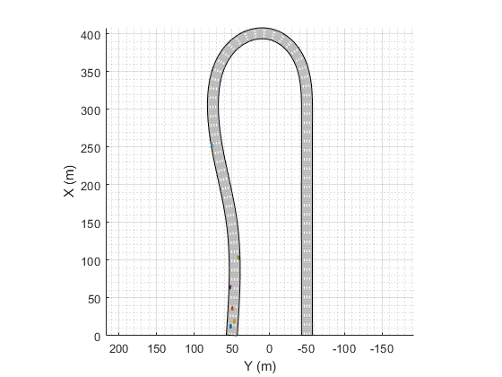
创建参考路径
本例中的所有局部路径规划都是针对参考路径执行的,由referencePathFrenet对象表示。 该对象可以返回给定路径长度的曲线状态,找到路径上与全局xy坐标最近的点,并便于实现全局坐标系与Frenet坐标系之间的坐标转换。
对于本例,参考路径被视为四车道公路的中心,并且waypoints与提供的drivingScenario对象中定义的道路匹配。
waypoints = [0 50; 150 50; 300 75; 310 75; 400 0; 300 -50; 290 -50; 0 -50];
% 路径点,单位米

refPath = referencePathFrenet(waypoints);
%定义一个通过Frenet转换的基于路径点的参考路径

ax = show(refPath);
%显示参考路径

axis(ax,'equal');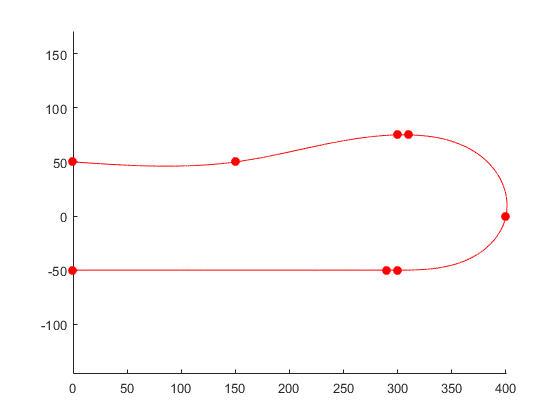
创建轨迹生成器
对于局部规划器来说,其目标通常是在满足当前运动学和动力学条件的同时,对朝着最终目标移动的各种可能的运动进行采样。TraightoryGeneratorFrenet对象通过使用四阶或五阶多项式轨迹将初始状态与一系列的终端状态连接起来来实现这一点。在Frenet坐标系中定义初始状态和终止状态,每个多项式解均要满足横纵向位置限制、速度和加速度边界条件,同时最小化跃度。
终端状态通常使用自定义行为来计算。 这些行为利用了在本地环境中发现的信息,例如车道信息、速度限制以及在自车附近的交通参与者的当前或未来状态来进行预测。
使用参考路径构造一个轨迹生成器Frenet对象:
connector = trajectoryGeneratorFrenet(refPath);创建动态碰撞检测器
dynamicCapsuleList对象是一种数据结构,它表示动态环境在一组在离散的时间步长上的状态。 然后,该环境可用于有效地验证自车的多个潜在轨迹。 场景中的每个对象由以下表示:
- 唯一整数值标识符
- 用于有效碰撞检查的胶囊几何的性质
- SE2状态的序列,其中每个状态表示时间上的离散快照。
在本例中,由TrajectoryGeneratorFrenet对象生成的轨迹发生在一段时间内,称为时间范围。 为了确保冲突检查覆盖所有可能的轨迹,dynamicCapsuleList对象应该包含跨越最大预期时间范围的所有参与者的预测轨迹。
capList = dynamicCapsuleList;
%创建动态胶囊列表
基于给定的参数为自车创建一个几何形状结构体。
egoID = 1; %自车ID
[egoID, egoGeom] = egoGeometry(capList,egoID);
%创建自车几何形状结构体的语法,返回胶囊列表中指定ID的几何形状信息

egoGeom.Geometry.Length = carLen; % 车长,米为单位
egoGeom.Geometry.Radius = carWidth/2; % 车宽,米为单位
egoGeom.Geometry.FixedTransform(1,end) = -carLen*rearAxleRatio; % 指定自车原点,单位米
%为创建好的自车几何结构体进行赋值操作
将自车添加到动态胶囊列表中。
updateEgoGeometry(capList,egoID,egoGeom);
%更新自车几何形状信息
将drivingScenario中的交通参与者添加到dynamicCapsuleList对象中。 这里设置了几何形状,并且在规划循环期间定义了状态。 可以看到dynamicCapsuleList现在包含一个自车和五个障碍物。
actorID = (1:5)';
%为障碍物分配ID,从1到5

actorGeom = repelem(egoGeom,5,1);
%将egoGeom矩阵中的每个元素复制到一个新矩阵的5x1块中

updateObstacleGeometry(capList,actorID,actorGeom)
%更新障碍物几何形状信息
结果如下图:
ans =
  dynamicCapsuleList with properties:

     MaxNumSteps: 31
          EgoIDs: 1
     ObstacleIDs: [5x1 double]
    NumObstacles: 5
         NumEgos: 1
通过交通情况规划自适应路线
规划程序支持局部路径规划策略,该策略在选择最优轨迹之前,基于环境的当前和预见状态对一组局部轨迹进行采样。 仿真循环被分成以下几个部分:
-
预先设定真实路面环境
-
创建终端状态
-
计算终端状态的成本
-
创建轨迹并进行运动学可行性检测
-
进行轨迹碰撞检测并选择最优轨迹
-
显示选择的轨迹并绘制场景仿真
预先设定真实路面环境
在动态环境中进行规划时,往往需要估计环境的状态或预测其一段时间内的状态。 为了简单起见,本例使用drivingScenario作为规划范围内每个参与者的轨迹的真实路面的数据源。 若要测试自定义的预测算法,可以使用自定义代码替换或修改ExampleHelperRetrieveActorGroundTrue函数。
function [curState, futureTrajectory, isRunning] = exampleHelperRetrieveActorGroundTruth(scenario, futureTrajectory, replanRate, maxHorizon)

% ExampleHelperRetrieveActorGroundTrue检索给定时间范围内每个执行元的当前状态和未来状态。
%
%   此功能仅供内部使用。 将来可能会被移除。
%   将drivingScenario对象SCENARIO提前到当前模拟时间步,并将每个参与者的状态存储在
%   FutureTrajectory中。 FutureTraimtory是一个m-y-1结构数组,包含场轨迹,一个n-y-6矩阵,
#   其中M是非自我行动者的数量,N是轨迹存储的未来步骤的数量。
%   N是使用规划器的重新规划率和规划轨迹可以发生的最大时间跨度,即maxhorizon来确定的。
%   该功能可由自定义预测模块或外部地面真值数据代替。
%
% Copyright 2020 The MathWorks, Inc.

    numActor = numel(futureTrajectory);
    curState = zeros(numActor,6);

    % Number of states needed
    minUpdateSteps = (1/replanRate)/scenario.SampleTime;
    maxNumStates = maxHorizon/scenario.SampleTime;
    statesNeeded = max(maxNumStates-size(futureTrajectory(1).Trajectory,1),minUpdateSteps);

    for i = 1:statesNeeded
        % Advance the scenario
        isRunning = advance(scenario);

        % Retrieve actor information
        poses = scenario.actorPoses;
        for j = 1:numActor
            actIdx = j+1;
            xy = poses(actIdx).Position(1:2);
            v  = norm(poses(actIdx).Velocity,2);
            th = atan2(poses(actIdx).Velocity(2),poses(actIdx).Velocity(1));
            k = poses(actIdx).AngularVelocity(3)/v/180*pi;
            % Assume acceleration = 0
            futureTrajectory(j).Trajectory(i,:) = [xy th k v 0];
        end
        if ~isRunning
            break;
        end
    end

    % Reorder the states
    for i = 1:numActor
        futureTrajectory(i).Trajectory = circshift(futureTrajectory(i).Trajectory,-statesNeeded,1);
        curState(i,:) = futureTrajectory(i).Trajectory(1,:);
    end
end
创建终端状态
自动驾驶的一个共同目标是确保规划的轨迹不仅是可行的,而且是自然的。 典型的高速公路驾驶包括车道保持、限速保持、变换车道、使速度适应交通情况等等。 每个自定义行为可能需要不同的环境信息。 此示例演示了如何生成实现三种行为的终端状态:巡航控制、车道变换和跟随前车。
巡航控制
exampleHelperBasicCruiseControl函数生成执行巡航控制行为的终端状态。 该函数使用自车的横向速度和一个时间范围来预测自车未来N秒的预期车道。计算出车道中心,使其成为终端状态的横向偏差,并将横向速度和加速度设为零。
对于纵向边界条件,终端速度设为道路限速,终端加速度设为零。 纵向位置不受限制,指定为NaN。 通过去掉经度约束,TrajectoryGeneratorFrenet 可以使用较低的4阶多项式来求解纵向边值问题,从而得到在给定时间范围内平滑地匹配道路速度的轨迹:
![]()
function [terminalStates, times] = exampleHelperBasicCruiseControl(refPath, laneWidth,
egoState, targetVelocity, dt)
% 要生成巡航的终端状态,需要输入参考路径、车道宽度、自车状态、目标速度和dt。

% exampleHelperBasicCruiseControl为巡航控制行为生成终端状态。
%
%   此功能仅供内部使用。 未来可能会被移除
%   [TERMINALSTATES,TIMES]=exampleHelperBasicCruiseControl
%   (REFPATH,LANEWIDTH,EGOSTATE,TARGETVELOCITY,DT)
%   生成终端状态,该状态试图在给定的时间跨度dt内遵循车道中心时遵守速度限制TARGETVELOCITY。
%   REFPATH是referencePathFrenet对象,用于将自车的状态EGOSTATE从全局坐标
%   [x y theta kappa v a]转换为Frenet坐标[S dS ddS L dL ddL]。
%   一旦处于Frenet坐标中,exampleHelperPredictLane被用于基于当前Frenet状态和给定时间跨度
%   内的零终端速度/加速度来预测车辆将驻留的未来车道。
%   函数返回TERMINALSTATES,这是一个n×6的矩阵,其中每一行都是一个Frenet状态,定义如下:
%   [NaN TARGETVELOCITY 0 L_lane 0 0],其中L_lane是预测车道中心的横向偏差。
%   TIMES也是以nx1的倍数向量返回的。
%
% Copyright 2020 The MathWorks, Inc.

    % Convert ego state to Frenet coordinates
    frenetState = global2frenet(refPath, egoState);

    % Determine current and future lanes
    futureLane = exampleHelperPredictLane(frenetState, laneWidth, dt);

    % Convert future lanes to lateral offsets
    lateralOffsets = (2-futureLane+.5)*laneWidth;

    % Return terminal states
    terminalStates      = zeros(numel(dt),6);

    terminalStates(:,1) = nan;
    %FrenetState第一列S,纵向偏差这里不做约束

    terminalStates(:,2) = targetVelocity;
    %FrenetState第二列dot_S,目标速度

    terminalStates(:,4) = lateralOffsets;
    %FrenetState第四列L,横向偏差
    %每一行都是一个Frenet状态

    times = dt(:);
end
车道变换
exampleHelperBasicLaneChange函数生成将车辆从当前车道转换到相邻车道的终端状态。 该函数首先确定自车的当前车道,然后检查左、右车道是否存在。 对于每个现有车道,终端状态以与巡航控制行为相同的方式定义,唯一的例外是终端速度设置为当前速度,而不是道路的限速:
![]()
function [terminalStates, times] = exampleHelperBasicLaneChange(refPath, laneWidth,
egoState, dt)

% ExampleHelperBasicLaneChange生成车道变更行为的终端状态。
%
%   此函数仅供内部使用。 未来可能会被移除
%   [TERMINALSTATES,TIMES]=exampleHelperBasicLaneChange(REFPATH,LANEWIDTH,EGOSTATE,DT)
%   生成终端状态TERMINALSTATES,该终端状态将自车从当前车道变换到相邻车道。
%   REFPATH是referencePathFrenet对象,用于将自车状态(EGOSTATE)从全局坐标
%   [x y theta kappa v]转换到Frenet坐标[S dS ddS L dL ddL]。
%
%   在Frenet坐标中,exampleHelperPredictLane返回当前车道号,然后计算相邻车道的中心相对于
%   REFPATH假设一个固定的车道宽度和4车道的道路。
%
%   函数返回TERMINALSTATES,这是一个n×6的矩阵,其中每一行都是一个Frenet状态,
%   定义如下:[NaN dS_cur 0 L_lane 0 0],其中dS_cur是ego车辆的当前纵向速度,
%   L_lane是车道中心的横向偏差。 TIMES也作为nx1向量的倍数。
%
% Copyright 2020 The MathWorks, Inc.

    if egoState(5) == 0
        terminalStates = [];
        times = [];
    else
        % Convert ego state to Frenet coordinates
        frenetState = global2frenet(refPath, egoState);

        % Get current lane
        curLane = exampleHelperPredictLane(frenetState, laneWidth, 0);

        % Determine if future lanes are available
        adjacentLanes = curLane+[-1 1];
        %[-1 1]其中-1检查左侧车道是否存在,1检查右侧车道是否存在

        validLanes = adjacentLanes > 0 & adjacentLanes <= 4;
        %validLanes为判断逻辑值0或1,型为[0 1]

        % Calculate lateral deviation for adjacent lanes
        lateralOffset = (2-adjacentLanes(validLanes)+.5)*laneWidth;%?????
        %若validLanes为0,则adjacentLanes(validLanes)不存在
        %若validLanes为1,则adjacentLanes(validLanes)=adjacentLanes = curLane+[-1 1]

        numLane = nnz(validLanes);
        %返回validLanes中非零元素的个数

        % Calculate terminal states
        terminalStates = zeros(numLane*numel(dt),6);

        terminalStates(:,1) = nan;
        %FrenetState中的S,纵向偏差不做约束

        terminalStates(:,2) = egoState(5);
        %FrenetState中的dot_S,当前纵向速度

        terminalStates(:,4) = repelem(lateralOffset(:),numel(dt),1);
        %FrenetState中的L,横向偏差
        %repelem将lateralOffset中的每个元素重复numel(dt)行1列,组成新的矩阵

        times = repmat(dt(:),numLane,1);
        %repmat将dt(:)重复numLane行1列
    end
end
跟随前车
exampleHelperBasicLeadVehicleFollow函数生成终端状态,试图找到并跟踪在自车前面的车辆。 该函数首先确定自车的当前车道。 对于每个提供的timeHorizon,该函数预测每个参与者的未来状态,找到与自车占用同一车道的所有交通参与者,并确定哪个是最近的领头车辆(如果没有找到领头车辆,则该函数不返回任何值)。
自车的终端状态是通过取领头车辆的位置和速度,并将终端纵向位置减少一定的安全距离来计算的:
![]()
![]()
function [terminalStates, times] = exampleHelperBasicLeadVehicleFollow(refPath,
laneWidth, safetyGap, egoState, actorState, dt)

% exampleHelperBasicLeadVehicleFollow生成车辆跟随行为的终端状态。
%
%   此函数仅供内部使用。 未来可能会被移除
%
%   [TERMINALSTATES,TIMES]=exampleHelperBasicLeadVehicleFollow
%   (REFPATH,LANEWIDTH,SAFETYGAP,EGOSTATE,ACTORSTATE,DT)
%   生成终端状态,在给定的时间范围内(dt),试图跟随距离自车最近的且在本车道上的前方车辆
%
%   REFPATH是referencePathFrenet对象,用于转换全局坐标下[x y theta kappa v a]和
%   Frenet坐标下[S dS ddS L dL ddL],自车和交通参与者的状态(EGOSTATE/ACTORSTATE)
%
%   在Frenet坐标中使用exampleHelperPredictLane来预测给定时间内(dt)所有参与者的未来车道,
%   选择在同一车道上最近的引导自车的交通参与者作为领头车辆
%
%   函数返回TERMINALSTATES,这是一个n×6的矩阵,其中每一行都是一个Frenet状态,定义如下:
%   [(S_lead-SAFETYGAP)dS_lead 0 L_lead dL_lead 0],其中*_lead表示最近的领头车辆的状态。
%
% Copyright 2020 The MathWorks, Inc.

    % Convert ego state to Frenet coordinates
    frenetStateEgo = global2frenet(refPath, egoState);

    % Get current lane of ego vehicle
    curEgoLane = exampleHelperPredictLane(frenetStateEgo, laneWidth, 0);

    % Get current and predicted lanes for each actor
    frenetStateActors = global2frenet(refPath, actorState);

    predictedActorLanes = zeros(numel(dt),size(actorState,1));
    for i = 1:size(actorState,1)
        predictedActorLanes(:,i) = exampleHelperPredictLane
        (frenetStateActors(i,:),laneWidth,dt);
    end

    % For each time horizon, find the closest car in the same lane as ego vehicle

    terminalStates = zeros(numel(dt),6);
    validTS = false(numel(dt),1);
    %validTS为dt行1列的逻辑数组

    for i = 1:numel(dt)
        % Find vehicles in same lane t seconds into the future
        laneMatch = curEgoLane == predictedActorLanes(i,:)';
        %laneMath保存了各个交通参与者是否与自车在同一车道的逻辑值(0或1)

        % Determine if they are ahead of the ego vehicle
        leadVehicle = frenetStateEgo(1) < frenetStateActors(:,1);
        %leadVehicle保存了各个交通参与者在纵向(S)上是否位于自车的前方的逻辑值(0或1)

        % Of these, find the vehicle closest to the ego vehicle (assume
        % constant longitudinal velocity)
        future_S = frenetStateActors(:,1) + frenetStateActors(:,2)*dt(i);
        %future_S=current_S+dot_current_s*dt 交通参与者dt时间的位移速度公式

        future_S(~leadVehicle | ~laneMatch) = inf;
        %将没在自车前方的和没与自车在同一车道的交通参与者的纵向(S)设置为无穷大

        [actor_S1, idx] = min(future_S);
        %选出dt时间后最小的位移对应的交通参与者,并编号

        % Check if any car meets the conditions
        if actor_S1 ~= inf
            % If distance is greater than safety gap, set the terminal
            % state behind this lead vehicle
            if frenetStateEgo(1)+safetyGap < actor_S1
                ego_S1 = actor_S1-safetyGap;
                terminalStates(i,:) =
                [ego_S1 frenetStateActors(idx,2) 0 frenetStateActors(idx,4:5) 0];
                validTS(i) = true;
            end
        end
    end
    % Remove any bad terminal states
    terminalStates(~validTS,:) = [];
    times = dt(validTS(:));
    times = times(:);
end
以上三个生成终端状态的函数中都用到了一个名为exampleHelperPredictLane的函数用以预测车道。其程序如下:
function laneNum = exampleHelperPredictLane(frenetState, laneWidth, dt)

% exampleHelperPredictLane预测给定时间集的车辆车道
%
%   此函数仅供内部使用。 未来可能会被移除
%   LANENUM=exampleHelperPredictLane(FRENETSTATE,LANEWIDTH,DT)基于其当前
%   FRENETSTATE(Frenet坐标中的1乘6矢量[S dS ddS L dL ddL])和以下假设,来预测
%   一辆车在未来一个或多个时间范围(DT)上的车道:
%
%        1)Bang Bang加速度控制,即开关式控制,继电器式控制
%        2)两个控制段横向加速度的变化是恒定的
%        3)终端横向速度=0
%        4)终端横向加速度=0
%        5)场景发生在具有固定车道宽度(LANEWIDTH)的4车道高速公路上
%
%   注意:当DT为零时,无法应用该运动学模型假设。
% Copyright 2020 The MathWorks, Inc.

    narginchk(3,3);
    %检查输入参数的个数,个数要满足>=3&&<=3

    laneBounds = [inf (2:-1:-2)*laneWidth -inf];
    %道路边界条件,inf为无穷大 -inf为无穷小,因为是4车道,所以取当前车道左右各两条,
    %共5车道(因为无法一上来就判断出自车在4车道中的哪个车道)

    laneNum = zeros(numel(dt),1);
    %每一个dt的车道标号,numel(dt)为数组dt中的元素个数,
    %zeros(numel(dt),1)为一个数组dt中的元素个数x1的全零矩阵

    for i = 1:numel(dt)
        if dt(i) == 0
            dLaneEgo = laneBounds-frenetState(4);
            %在边界条件的基础上减去当前横向偏差

            laneNum(i) = min(find(dLaneEgo(2:(end-1)) >= 0 & dLaneEgo(3:(end)) < 0,1),4);
            %从内向外依次看,同时满足dLaneEgo(2:(end-1)) >= 0 & dLaneEgo(3:(end)时,
            %就出现了一个形如[0 1 0 0 0]的矩阵,find函数找到其非零元素对应的序号,2,
            %再与4(预设了5条车道,实际上最多4条)作比较取最小,即为当前车道号。

        else
            % Retrieve current velocity/acceleration/time
            t  = dt(i);
            a0 = frenetState(6);%横向加速度
            v0 = frenetState(5);%横向速度

            % Solve for the constant change in acceleration and time of
            % application that arrest the ego vehicle's lateral
            % velocity and acceleration over a given number of seconds.
            if a0 == 0
                avgAcc = -v0/t;
                Ldiff = v0*t + avgAcc/2*t^2;
            else
                a = a0;
                b = (-2*v0-2*a0*t);
                c = (v0*t+a0/2*t^2);
                %一元二次方程 ax^2+bx+c=0

                % Possible time switches
                r = (-b+(sqrt(b^2-4*a*c).*[-1 1]))/(2*a);
                %一元二次方程求根公式

                % Select the option that occurs in the future
                rS = r(r>0 & r <= t);
                %方程的解为时间time

                % Calculate the constant change in acceleration
                da0 = a0/(t-2*rS);

                % Predict total distance traveled over t seconds
                Ldiff = v0*t + a0/2*t^2 + da0/6*t^3 - da0/6*(t-rS)^3;
            end
            % Find distance between predicted offset and each lane
            dLaneEgo = laneBounds-(frenetState(4)+Ldiff);

            % Determine future lane
            laneNum(i) = min(find(dLaneEgo(2:(end-1)) >= 0 & dLaneEgo(3:(end)) < 0,1),4);
        end
    end
end
计算终端状态的成本
在终端状态已经生成之后,可以评估它们的成本。 轨迹评估和对潜在解决方案进行优先排序的方法具有很强的主观性。 为了简单起见,exampleHelperEvaluateTSCost函数将成本定义为三个加权和的组合。
-
Lateral Deviation Cost (ClatDev) — 对偏离车道中心的状态进行惩罚的正权重。
![]()
![]()
-
Time Cost (Ctime) — 一种在较长时间间隔内发生的运动进行优先排序,从而产生更平滑的轨迹的负权重。
![]()
-
Terminal Velocity Cost (Cspeed) — 一个优先考虑使运动保持速度限制,从而减少动态运动剧烈程度的正权重。
![]()
function costs = exampleHelperEvaluateTSCost(terminalStates, times, laneWidth, speedLimit, speedWeight, latWeight, timeWeight)

% exampleHelperEvaluateTSCost评估轨迹成本。
%
%   此功能仅供内部使用。 未来可能会被移除
%
%   COSTS=exampleHelperEvaluateTSCost
%   (TERMINALSTATES,times,laneWidth,speedLimit,speedWeight,latWeight,timeWeight)
%   评估由Frenet状态、TERMINALSTATES和相应的timespans,times向量组成的n-x-6矩阵的成本。
%   成本是基于车道中心的横向偏差,计算方法包括车道宽度、与所需速度的偏差、
%   速度限制和轨迹所需的时间跨度。
%   这些度量标准中的每一个都分别由伴随的权重LATWEIGHT、SPEEDWEIGHT、和TIMEWEIGHT进行缩放。
%
% Copyright 2020 The MathWorks, Inc.

    % Find lateral deviation from nearest lane center
    laneCenters = (1.5:-1:-1.5)*laneWidth;
    latDeviation = abs(laneCenters-terminalStates(:,4));
    %abs()为绝对值函数

    % Calculate lateral deviation cost
    latCost = min(latDeviation,[],2)*latWeight;
    %min(A,[],dim):dim取1时,同min(A);dim取2时,得到每行中的最小值构成的列向量。

    % Calculate trajectory time cost
    timeCost = times*timeWeight;

    % Calculate terminal speed vs desired speed cost
    speedCost = abs(terminalStates(:,2)-speedLimit)*speedWeight;

    % Return cumulative cost
    costs = latCost+timeCost+speedCost;
end
创建轨迹并进行运动学可行性检测
除了具有最小成本的终端状态外,最优轨迹还必须满足与运动学可行性和乘坐舒适性有关的附加约束条件。 轨迹约束是一种强制执行的乘坐品质需求,但它们是以降低行驶包线为代价的。
在本例中,exampleHelperEvaluateTrajectory函数验证每个轨迹是否满足以下约束:
-
MaxAcceleration: 整个轨迹的绝对加速度必须低于规定值。 较小的加速度会降低驾驶攻击性,并消除运动上不可行的轨迹。 这种限制可能消除本可以由车辆执行的运动操作。 -
MaxCurvature: 在整个轨道上允许的最小转弯半径。 与MaxAcceleration一样,降低该值会带来更平稳的驾驶体验,但可能会消除其他可行的轨迹。 -
MinVelocity: 这个约束通过设定一个最小速度来限制自车只向前运动。 这种限制在高速公路行驶情况下是需要的,并且消除了符合过约束或条件差的边界值的轨迹。
function isValid = exampleHelperEvaluateTrajectory(globalTrajectory, maxAcceleration, maxCurvature, minVelocity)
%exampleHelperEvaluateTrajectory Evaluate trajectory constraints.
%
%   This function is for internal use only. It may be removed in the future

%   ISVALID = exampleHelperEvaluateTrajectory(GLOBALTRAJECTORY, MAXACCELERATION, MAXCURVATURE, MINVELOCITY)
%   Takes in a N-element struct array of trajectories, GLOBALTRAJECTORY, and
%   checks whether each trajectory violates the MAXACCELERATION, MAXCURVATURE,
%   or MINVELOCITY constraints.
%
%   Each element of GLOBALTRAJECTORY contains the fields Trajectory, an
%   N-by-[x y theta kappa v a] matrix, and Times, an N-by-1 vector of timesteps.
%
%   Returns an N-by-1 vector of logicals, ISVALID, where an entry of false
%   means that the corresponding trajectory violated one or more constraints,
%   and true means that all constraints were met.
%
% Copyright 2020 The MathWorks, Inc.

    isValid = true(numel(globalTrajectory),1);
    for i = 1:numel(globalTrajectory)
        % Acceleration constraint
        accViolated  = any(abs(globalTrajectory(i).Trajectory(:,6)) > abs(maxAcceleration));

        % Curvature constraint
        curvViolated = any(abs(globalTrajectory(i).Trajectory(:,4)) > abs(maxCurvature));

        % Velocity constraint
        velViolated  = any(globalTrajectory(i).Trajectory(:,5) < minVelocity);

        isValid(i) = ~accViolated && ~curvViolated && ~velViolated;
    end
end
进行轨迹碰撞检测并选择最优轨迹
规划过程的最后一步是选择最佳的轨迹,同时也会选择出无碰撞路径。 碰撞检查常常被推迟到最后,因为它的操作计算成本很高,所以通过评估成本和首先分析约束,可以将无效的轨迹从备选中移除。 然后可以以最佳顺序检查剩余的轨迹是否发生碰撞,直到找到无碰撞路径或评估完所有轨迹为止。
设置仿真环境和规划程序
本节定义运行模拟器所需的属性以及规划器和执行工具使用的参数。 将同步Scenario.SampleTime和Connector.TimeResolution等属性,以便在真实环境中的交通参与者轨迹和规划的自车轨迹发生在相同的时间步长上。 相应地,replanRate、timeHorizons和maxHorizon被设置为仿真频率的整数倍。
如前一节所述,选择权重和约束,在坚持道路规则的前提下确保平稳的行驶轨迹。
最后,定义speedLimit和safetyGap参数,它们用于为规划器生成终端状态。
% Synchronize the simulator's update rate to match the trajectory generator's
% discretization interval.
scenario.SampleTime = connector.TimeResolution; % in seconds

% Define planning parameters.
replanRate = 10; % Hz

% Define the time intervals between current and planned states.
timeHorizons = 1:3; % in seconds
maxHorizon = max(timeHorizons); % in seconds

% Define cost parameters.
latDevWeight    =  1;
timeWeight      = -1;
speedWeight     =  1;

% Reject trajectories that violate the following constraints.
maxAcceleration =  15; % in meters/second^2
maxCurvature    =   1; % 1/meters, or radians/meter
minVelocity     =   0; % in meters/second

% Desired velocity setpoint, used by the cruise control behavior and when
% evaluating the cost of trajectories.
speedLimit = 11; % in meters/second

% Minimum distance the planner should target for following behavior.
safetyGap = 10; % in meters
初始化仿真器
初始化仿真器并创建追逐图(chasePlot)
[scenarioViewer,futureTrajectory,actorID,actorPoses,egoID,egoPoses,stepPerUpdate,
egoState,isRunning,lineHandles] = ...
exampleHelperInitializeSimulator(scenario,capList,refPath,laneWidth,replanRate,carLen);
运行驾驶仿真
tic
while isRunning
    % Retrieve the current state of actor vehicles and their trajectory over
    % the planning horizon.
    [curActorState,futureTrajectory,isRunning] = ...
        exampleHelperRetrieveActorGroundTruth(scenario,futureTrajectory,replanRate,maxHorizon);
% Generate cruise control states.
[termStatesCC,timesCC] = exampleHelperBasicCruiseControl(...
refPath,laneWidth,egoState,speedLimit,timeHorizons);
% Generate lane change states.
[termStatesLC,timesLC] = exampleHelperBasicLaneChange(...
refPath,laneWidth,egoState,timeHorizons);
% Generate vehicle following states.
[termStatesF,timesF] = exampleHelperBasicLeadVehicleFollow(...
refPath,laneWidth,safetyGap,egoState,curActorState,timeHorizons); % Combine the terminal states and times.
allTS = [termStatesCC; termStatesLC; termStatesF];
allDT = [timesCC; timesLC; timesF];
numTS = [numel(timesCC); numel(timesLC); numel(timesF)];
% Evaluate cost of all terminal states.
costTS = exampleHelperEvaluateTSCost(allTS,allDT,laneWidth,speedLimit,...
speedWeight, latDevWeight, timeWeight); % Generate trajectories.
egoFrenetState = global2frenet(refPath,egoState);
[frenetTraj,globalTraj] = connect(connector,egoFrenetState,allTS,allDT);
% Eliminate trajectories that violate constraints.
isValid = exampleHelperEvaluateTrajectory(globalTraj,maxAcceleration,maxCurvature,minVelocity); % Update the collision checker with the predicted trajectories
% of all actors in the scene.
for i = 1:numel(actorPoses)
actorPoses(i).States = futureTrajectory(i).Trajectory(:,1:3);
end
updateObstaclePose(capList,actorID,actorPoses);
% Determine evaluation order.
[cost, idx] = sort(costTS);
optimalTrajectory = [];
trajectoryEvaluation = nan(numel(isValid),1);
% Check each trajectory for collisions starting with least cost.
for i = 1:numel(idx)
if isValid(idx(i))
% Update capsule list with the ego object's candidate trajectory.
egoPoses.States = globalTraj(idx(i)).Trajectory(:,1:3);
updateEgoPose(capList,egoID,egoPoses);
% Check for collisions.
isColliding = checkCollision(capList);
if all(~isColliding)
% If no collisions are found, this is the optimal.
% trajectory.
trajectoryEvaluation(idx(i)) = 1;
optimalTrajectory = globalTraj(idx(i)).Trajectory;
break;
else
trajectoryEvaluation(idx(i)) = 0;
end
end
end % Display the sampled trajectories.
lineHandles = exampleHelperVisualizeScene(lineHandles,globalTraj,isValid,trajectoryEvaluation);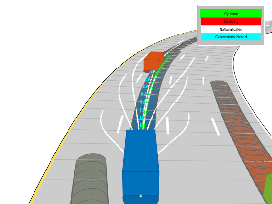
hold on;
show(capList,'TimeStep',1:capList.MaxNumSteps,'FastUpdate',1);
hold off;
if isempty(optimalTrajectory)
% All trajectories either violated a constraint or resulted in collision.
%
% If planning failed immediately, revisit the simulator, planner,
% and behavior properties.
%
% If the planner failed midway through a simulation, additional
% behaviors can be introduced to handle more complicated planning conditions.
error('No valid trajectory has been found.');
else
% Visualize the scene between replanning.
for i = (2+(0:(stepPerUpdate-1)))
% Approximate realtime visualization.
dt = toc;
if scenario.SampleTime-dt > 0
pause(scenario.SampleTime-dt);
end
egoState = optimalTrajectory(i,:);
scenarioViewer.Actors(1).Position(1:2) = egoState(1:2);
scenarioViewer.Actors(1).Velocity(1:2) = [cos(egoState(3)) sin(egoState(3))]*egoState(5);
scenarioViewer.Actors(1).Yaw = egoState(3)*180/pi;
scenarioViewer.Actors(1).AngularVelocity(3) = egoState(4)*egoState(5);
% Update capsule visualization.
hold on;
show(capList,'TimeStep',i:capList.MaxNumSteps,'FastUpdate',1);
hold off;
% Update driving scenario.
advance(scenarioViewer);
ax = gca;
ax.ZLim = [-100 100];
tic;
end
end
end规划器的自定义和附加注意事项
自定义解决方案通常涉及许多可调参数,每个参数都能够以难以预测的方式改变最终行为。 本节重点介绍了一些特定功能属性及其对上述规划器的影响。 然后,本建议提供了调优或扩充自定义逻辑的方法。
动态胶囊列表
如前所述,dynamicCapsuleList对象充当一个时态数据库,它缓存了障碍物的预测轨迹。 你可以在一段时间内执行与一个或多个自我身体的碰撞检查。 MaxNumSteps属性确定对象检查的时间步骤总数。 在上面的模拟循环中,属性被设置为31。 这个值意味着规划器检查任何轨迹的整个1-3秒跨度(每0.1秒采样一次)。 现在,增加timehorizons中的最大值:
timeHorizons = 1:5; % in seconds
maxTimeHorizon = max(timeHorizons); % in secondsThere are now two options:
-
The
MaxNumStepsproperty is left unchanged. -
The
MaxNumStepsproperty is updated to accommodate the new max timespan.
If the property is left unchanged, then the capsule list only validates the first 3 seconds of any trajectory, which may be preferable if computational efficiency is paramount or the prediction certainty drops off quickly.
Alternatively, one may be working with ground truth data (as is shown above), or the future state of the environment is well known (e.g. a fully automated environment with centralized control). Since this example uses ground truth data for the actors, update the property.
现在有两种选择:
- MaxNumSteps属性保持不变。
- 更新MaxNumSteps属性以适应新的最大时间间隔。
如果属性保持不变,则胶囊列表仅验证任何轨迹的前3秒,如果计算效率至关重要或预测确定性迅速下降,则这可能是更好的选择。
或者,可以使用地面真实数据(如上所示)或环境的未来状态是众所周知的(例如,具有集中控制的完全自动化的环境)。 由于此示例参与者使用的是环境真相数据,因此更新属性。
capList.MaxNumSteps = 1+floor(maxTimeHorizon/scenario.SampleTime);Another, indirectly tunable, property of the list is the capsule geometry. The geometry of the ego vehicle or actors can be inflated by increasing the Radius, and buffer regions can be added to vehicles by modifying the Length and FixedTransform properties.
Inflate the ego vehicle's entire footprint by increasing the radius.
列表的另一个间接可调的属性是胶囊几何形状。 可以通过增加半径来扩大自我车辆或行动者的几何形状,并且可以通过修改长度和FixedTransform属性来向车辆添加缓冲区。
通过增加半径来扩大自我车辆的整个行驶空间。
egoGeom.Geometry.Radius = laneWidth/2; % in meters
updateEgoGeometry(capList,egoID,egoGeom);
向所有参与者添加一个前后缓冲区。
actorGeom(1).Geometry.Length = carLen*1.5; % in meters
actorGeom(1).Geometry.FixedTransform(1,end) =
-actorGeom(1).Geometry.Length*rearAxleRatio; % in meters
actorGeom = repmat(actorGeom(1),5,1);
updateObstacleGeometry(capList,actorID,actorGeom);更新属性后的重新运行仿真
重新运行模拟。 更新后产生的模拟有几个有趣的发展:
- 更长的五秒时间范围带来了更平稳的驾驶体验。 由于负权重timeWeight,规划器仍然优先考虑较长的轨迹。
- 更新的MaxNumSteps属性启用了对整个轨迹的冲突检查。 当与较长的规划视野配对时,规划器识别并丢弃先前最优的左车道改变,并返回到原始车道。
- 扩大的胶囊更早发现碰撞,并拒绝一个轨迹,这导致更保守的驾驶行为。 这样做的一个潜在缺点是减少了规划包络,这可能会导致规划者无法找到一个有效的轨迹。
% Initialize the simulator and create a chasePlot viewer.
[scenarioViewer,futureTrajectory,actorID,actorPoses,egoID,egoPoses,stepPerUpdate,
egoState,isRunning,lineHandles] = ...
exampleHelperInitializeSimulator(scenario,capList,refPath,laneWidth,replanRate,carLen);
tic;
while isRunning
% Retrieve the current state of actor vehicles and their trajectory over
% the planning horizon.
[curActorState,futureTrajectory,isRunning] = exampleHelperRetrieveActorGroundTruth(...
scenario,futureTrajectory,replanRate,maxHorizon);
    % Generate cruise control states.
    [termStatesCC,timesCC] = exampleHelperBasicCruiseControl(...
        refPath,laneWidth,egoState,speedLimit,timeHorizons);

    % Generate lane change states.
    [termStatesLC,timesLC] = exampleHelperBasicLaneChange(...
        refPath,laneWidth,egoState,timeHorizons);

    % Generate vehicle following states.
    [termStatesF,timesF] = exampleHelperBasicLeadVehicleFollow(...
        refPath,laneWidth,safetyGap,egoState,curActorState,timeHorizons);
% Combine the terminal states and times.
allTS = [termStatesCC; termStatesLC; termStatesF];
allDT = [timesCC; timesLC; timesF];
numTS = [numel(timesCC); numel(timesLC); numel(timesF)];
% Evaluate cost of all terminal states.
costTS = exampleHelperEvaluateTSCost(allTS,allDT,laneWidth,speedLimit, ...
speedWeight,latDevWeight,timeWeight);
% Generate trajectories.
egoFrenetState = global2frenet(refPath,egoState);
[frenetTraj,globalTraj] = connect(connector,egoFrenetState,allTS,allDT);
% Eliminate trajectories that violate constraints.
isValid = exampleHelperEvaluateTrajectory(...
globalTraj, maxAcceleration, maxCurvature, minVelocity);
% Update the collision checker with the predicted trajectories
% of all actors in the scene.
for i = 1:numel(actorPoses)
actorPoses(i).States = futureTrajectory(i).Trajectory(:,1:3);
end
updateObstaclePose(capList, actorID, actorPoses);
% Determine evaluation order.
[cost, idx] = sort(costTS);
optimalTrajectory = [];
trajectoryEvaluation = nan(numel(isValid),1);
% Check each trajectory for collisions starting with least cost.
for i = 1:numel(idx)
if isValid(idx(i))
% Update capsule list with the ego object's candidate trajectory.
egoPoses.States = globalTraj(idx(i)).Trajectory(:,1:3);
updateEgoPose(capList, egoID, egoPoses);
% Check for collisions.
isColliding = checkCollision(capList);
if all(~isColliding)
% If no collisions are found, this is the optimal
% trajectory.
trajectoryEvaluation(idx(i)) = 1;
optimalTrajectory = globalTraj(idx(i)).Trajectory;
break;
else
trajectoryEvaluation(idx(i)) = 0;
end
end
end
% Display the sampled trajectories.
lineHandles = exampleHelperVisualizeScene(lineHandles, globalTraj, isValid, trajectoryEvaluation);
if isempty(optimalTrajectory)
% All trajectories either violated a constraint or resulted in collision.
%
% If planning failed immediately, revisit the simulator, planner,
% and behavior properties.
%
% If the planner failed midway through a simulation, additional
% behaviors can be introduced to handle more complicated planning conditions.
error('No valid trajectory has been found.');
else
% Visualize the scene between replanning.
for i = (2+(0:(stepPerUpdate-1)))
% Approximate realtime visualization.
dt = toc;
if scenario.SampleTime-dt > 0
pause(scenario.SampleTime-dt);
end
egoState = optimalTrajectory(i,:);
scenarioViewer.Actors(1).Position(1:2) = egoState(1:2);
scenarioViewer.Actors(1).Velocity(1:2) = [cos(egoState(3)) sin(egoState(3))]*egoState(5);
scenarioViewer.Actors(1).Yaw = egoState(3)*180/pi;
scenarioViewer.Actors(1).AngularVelocity(3) = egoState(4)*egoState(5);
% Update capsule visualization.
hold on;
show(capList,'TimeStep',i:capList.MaxNumSteps,'FastUpdate',1);
hold off;
% Update driving scenario.
advance(scenarioViewer);
ax = gca;
ax.ZLim = [-100 100];
tic;
end
end
end