Halcon图像预处理-图像的变换与校正
提示:本文参考了网上其他相关文章,如有侵权,请联系作者。
文章目录
- 前言
- 一、图像处理与矩阵(Matrix)、齐次坐标
-
- 1.图像的平移
- 2.图像的旋转
- 3.图像的缩放
- 4.补充
- 二、仿射变换
-
- 1.仿射变换矩阵
- 2.应用仿射变换矩阵
- 三、透视变换(投影变换)
-
- 1.投影变换
- 2.Halcon中的投影变换实例
- 3.其他实例
- 总结
前言
获得了相机采集的图像之后,图像质量往往会与预想的有所差异,如出现形状失真、亮度低、图像噪声大等问题,因此需要对图像进行即时校正和图像增强等预处理,方便后续的检测和识别。图像预处理是非常关键的一个环节,输出的图像质量关系到识别的准确率和速度。本篇文章着重介绍图像的校正和变换。
一、图像处理与矩阵(Matrix)、齐次坐标
图像的缩放变换和旋转变换,可以用矩阵乘法的形式来表达变换后的像素位置映射关系。
一个点p0的位置可以用3个坐标表示(xp,yp,zp),这3个坐标也可以看成一个3D向量。
1.图像的平移
如果把这个点移动(xt,yt)个向量,相当于在p坐标的左边乘以一个平移矩阵T。设平移后的点位Pt,如下面的公式所示。
p t = T ∗ p 0 = [ 1 0 x t 0 1 y t 0 0 1 ] ∗ p 0 \begin{gathered} p_t=T*p_0=\begin{bmatrix} 1 & 0& x_t \\0 & 1& y_t\\ 0 & 0&1 \end{bmatrix}*p_0 \quad \end{gathered} pt=T∗p0=⎣⎡100010xtyt1⎦⎤∗p0 从上面的公式可以看到,平移变换是矩阵乘法的形式,而不是矩阵加法的形式!为什么是乘法,原因就是图像的几何变换通常不是单一的,就是说会经常性的缩放、旋转、平移一起变换。例如先放大2倍,然后旋转45度,然后再缩小0.5倍。而缩放和旋转的运算都是通过矩阵乘法来实现的,为了方便计算和降低运算量,就将平移变换采用矩阵乘法的形式。这种方法就是“升维”,引入“齐次坐标”(homogeneous coordinates),将图像从平面2D坐标变成3D坐标。我们看看平移变换的矩阵形式:
[ x 2 y 2 ] = [ x 1 y 1 ] + [ x t y t ] \begin{gathered} \begin{bmatrix} x_2\\ y_2\end{bmatrix}=\begin{bmatrix} x_1\\ y_1\end{bmatrix}+\begin{bmatrix} x_t\\ y_t\end{bmatrix} \quad \end{gathered} [x2y2]=[x1y1]+[xtyt] 将其升维,变成3维,上式就可以表示成:
[ x 2 y 2 1 ] = [ 1 0 x t 0 1 y t 0 0 1 ] [ x 1 y 1 1 ] \begin{gathered} \begin{bmatrix} x_2\\ y_2\\\ 1\end{bmatrix}=\begin{bmatrix} 1&0&x_t\\ 0&1&yt\\0&0&1\end{bmatrix}\begin{bmatrix} x_1\\ y_1\\1\end{bmatrix} \quad \end{gathered} ⎣⎡x2y2 1⎦⎤=⎣⎡100010xtyt1⎦⎤⎣⎡x1y11⎦⎤ 这是个非常优美的地方,学习过矩阵乘法的同学可以算一下右边的式子,是否最终结果与前面是一样的。这样,平移变换通过升维后的齐次坐标,也变成了矩阵乘法的形式。当然缩放变换和旋转变换的矩阵形式也得改一改,统一变成3维的形式。运算形式统一后,以后所有的变换,不管怎样变换,变换多少次,都可以表示成一连串的矩阵相乘了,这是多么的方便。
这就是引入齐次坐标的作用,把各种变换都统一了起来。即它提供了用矩阵运算把二维、三维甚至高维空间中的一个点集从一个坐标系变换到另一个坐标系的有效方法。
顺便介绍下矩阵乘法的运算规则:
[ 1 0 x t 0 1 y t 0 0 1 ] [ x 1 y 1 1 ] = [ 1 ∗ x 1 + 0 ∗ y 1 + x t ∗ 1 0 ∗ x 1 + 1 ∗ y 1 + y t ∗ 1 0 ∗ x 1 + 0 ∗ y 1 + 1 ∗ 1 ] \begin{gathered} \begin{bmatrix} 1&0&x_t\\ 0&1&y_t\\0&0&1\end{bmatrix}\begin{bmatrix} x_1\\ y_1\\1\end{bmatrix}=\begin{bmatrix} 1*x_1+0*y_1+x_t*1\\0*x_1+1*y_1+y_t*1\\0*x_1+0*y_1+1*1\end{bmatrix} \quad \end{gathered} ⎣⎡100010xtyt1⎦⎤⎣⎡x1y11⎦⎤=⎣⎡1∗x1+0∗y1+xt∗10∗x1+1∗y1+yt∗10∗x1+0∗y1+1∗1⎦⎤
2.图像的旋转
如果将这个点在二维平面上绕坐标原点旋转角度γ,相当于在p0坐标的左边乘以一个旋转矩阵R。设旋转后的点为pr,公式如下所示。
p r = R ∗ p 0 = [ c o s γ − s i n γ 0 s i n γ c o s γ 0 0 0 1 ] ∗ p 0 \begin{gathered} p_r=R*p_0=\begin{bmatrix} cosγ &-sinγ& 0\\sinγ & cosγ& 0\\ 0 & 0&1 \end{bmatrix}*p_0 \quad \end{gathered} pr=R∗p0=⎣⎡cosγsinγ0−sinγcosγ0001⎦⎤∗p0
3.图像的缩放
假设这个点在二维平面上,沿x轴方向放大sx倍,沿y轴方向放大sy倍,那么变化后的该点的坐标记为ps,公式如下所示。
p s = S ∗ p 0 = [ s x 0 0 0 s y 0 0 0 1 ] ∗ p 0 \begin{gathered} p_s=S*p_0=\begin{bmatrix} s_x&0& 0\\0 & s_y& 0\\ 0 & 0&1 \end{bmatrix}*p_0 \quad \end{gathered} ps=S∗p0=⎣⎡sx000sy0001⎦⎤∗p0 补充一个知识点-对角矩阵。当一个方阵上所有非对角线上的元素均为0时,即i≠j时aij=0,该矩阵即为对角矩阵。例如:
[ 1 0 0 0 5 0 0 0 2 ] \begin{gathered} \begin{bmatrix} 1&0&0\\ 0&5&0\\0&0&2\end{bmatrix} \quad \end{gathered} ⎣⎡100050002⎦⎤ 它可用于缩放变换,假如我们要将 (x, y) 分别缩放m倍和n倍,变为 (mx, ny) 那么就可以用下面矩阵来表达:
[ m 0 0 n ] [ x y ] = [ m ∗ x + 0 ∗ y 0 ∗ x + n ∗ y ] \begin{gathered} \begin{bmatrix} m&0\\ 0&n\end{bmatrix}\begin{bmatrix} x\\ y\end{bmatrix}=\begin{bmatrix} m*x+0*y\\0*x+n*y\end{bmatrix} \quad \end{gathered} [m00n][xy]=[m∗x+0∗y0∗x+n∗y] 该对角矩阵也可称为缩放矩阵。
4.补充
平移、缩放和旋转都需要有一个参考点,围绕该点进行仿射变换操作。
在坐标系中,我们x轴的单位向量为(1, 0,0),y轴为(0,1,0),z轴为(0,0,1),那么他们所组成的矩阵即为:
[ 1 0 0 0 1 0 0 0 1 ] \begin{gathered} \begin{bmatrix} 1&0&0\\ 0&1&0\\0&0&1\end{bmatrix} \quad \end{gathered} ⎣⎡100010001⎦⎤ 它既是单位矩阵,又是正交矩阵。
二、仿射变换
把平移、旋转和缩放结合起来,可以在Halcon中使用仿射变换的相关算子。一个仿射变换矩阵包括平移向量和旋转向量。
1.仿射变换矩阵
在仿射变换前,先确定仿射变换矩阵,步骤如下。
1)、使用hom_mat2d_identity(HomMat2DIdentity)创建一个空的仿射变换矩阵;
2)、指定变换的参数,这里可以指定平移、缩放和旋转参数,举例如下:
a:设置平移矩阵,向x轴正方向平移30个像素,向y轴正方向平移30个像素:hom_mat2d_translate(HomMat2DIdentity, 30, 30, HomMat2DTranslate);
b:设置旋转矩阵,以点(px,py)为参考点,旋转角度phi:hom_mat2d_rotate(HomMat2DTranslate,rad(phi), Px, Py, HomMat2DRotate);
c:设置缩放矩阵,以点(px,py)为参考点,放大2倍:hom_mat2d_scale(HomMat2DRotate, 2, 2, Px, Py,HomMat2DScale)。
2.应用仿射变换矩阵
仿射变换矩阵可以应用于像素点(Pixel)、二维点(Point)、图像(Image)、区域(Region)及XLD轮廓等对象。下面分别举例。
1)、应用于像素点:使用affine_trans_pixel算子;
2)、应用于二维点:使用affine_trans_point_2d算子;
3)、应用于图像:使用affine_trans_image算子;
4)、应用于区域:使用affine_trans_region算子;
5)、应用于XLD轮廓:使用affine_trans_contour_xld算子;
三、透视变换(投影变换)
1.投影变换
仿射变换其实是投影变换的一个特殊例子,其特殊性在于变换后图像的形状仍然维持原状。投影变换包括的情况很多,有可能变换前后图像的形状发生了很大的改变,如对边不再平行,或者发生了透视畸变等,这时可以使用投影变换使其恢复原状。其步骤与仿射变换类似,首先计算投影变换矩阵,然后计算投影变换参数,最后将投影变换矩阵映射到对象上。
要计算投影变换矩阵,应找出投影区域的特征点的位置及其投影后的位置,通过hom_vector_to_proj_hom_mat2d算子进行换算,就可以根据已知的投影对应的点的值计算投影变换矩阵。然后使用projective_trans_image对图像进行投射变换,就能得到投影后的图像了。
hom_vector_to_proj_hom_mat2d( : : Px, Py, Pw, Qx, Qy, Qw, Method : HomMat2D)算子介绍:
1)、主要用途:通过至少4个点对应计算出符合下列方程式最佳的齐次映射转换矩阵HomMat2D。
H o m M a t 2 D . ( P x P y P w ) = ( Q x Q y Q w ) HomMat2D.\left( \begin{matrix} P_x \\ P_y \\ P_w \\ \end{matrix} \right)=\left( \begin{matrix} Q_x \\ Q_y \\ Q_w\\ \end{matrix} \right) HomMat2D.⎝⎛PxPyPw⎠⎞=⎝⎛QxQyQw⎠⎞
2)、Px和Py为图像变换前的顶点坐标,用元组的形式表示,比如[70,270,270,70];
3)、Qx和Qy为图像投影变换后的顶点坐标,也用元组的形式表示;
4)、通常情况下,Pw和Qw被设为1(见下面2个实例);
2.Halcon中的投影变换实例
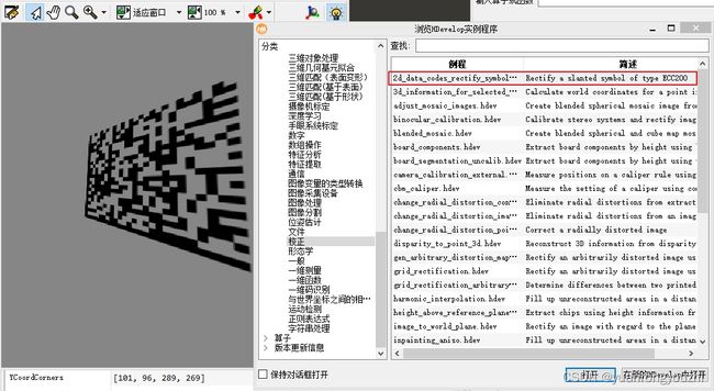
在文件(F)→浏览HDevelop示例程序(E)→分类→方法→校正对话框中,可以找到投影变换的例子,如下图。

代码如下:
* This program demonstrates how to read a slanted
* 2d data code by preprocessing with rectification
*
dev_update_off ()
dev_close_window ()
* Get the image and display it
read_image (Image_slanted, 'datacode/ecc200/ecc200_to_preprocess_001')
dev_open_window_fit_image (Image_slanted, 0, 0, -1, -1, WindowHandle)
set_display_font (WindowHandle, 14, 'mono', 'true', 'false')
dev_set_color ('green')
dev_set_line_width (3)
Message := 'This program demonstrates how to preprocess'
Message[1] := 'a slanted 2d data code with rectification'
Message[2] := 'before reading the data code symbol.'
disp_message (WindowHandle, Message, 'window', 12, 12, 'black', 'true')
disp_continue_message (WindowHandle, 'black', 'true')
stop ()
* Initialize coordinates
XCoordCorners := [130,225,290,63]
YCoordCorners := [101,96,289,269]
*
* Display the slanted image and the corners of the symbol
gen_cross_contour_xld (Crosses, XCoordCorners, YCoordCorners, 6, 0.785398)
dev_display (Image_slanted)
dev_display (Crosses)
disp_message (WindowHandle, 'Slanted image', 'window', 12, 12, 'black', 'true')
Message := 'The marked corners are used to generate a'
Message[1] := 'homogeneous transformation matrix which'
Message[2] := 'defines the projective transformation for'
Message[3] := 'the rectification of the symbol.'
disp_message (WindowHandle, Message, 'window', 380, 12, 'black', 'true')
disp_continue_message (WindowHandle, 'black', 'true')
stop ()
*
* First generate a transformation matrix using the given points
* of the corners of the data code symbol and the corresponding points
* of a quare.
hom_vector_to_proj_hom_mat2d (XCoordCorners, YCoordCorners, [1,1,1,1], [70,270,270,70], [100,100,300,300], [1,1,1,1], 'normalized_dlt', HomMat2D)
*
* Now rectifiy the slanted image by applying the projective transformation
projective_trans_image (Image_slanted, Image_rectified, HomMat2D, 'bilinear', 'false', 'false')
*
* Create the data code model and search
* for the data code in the rectified image
create_data_code_2d_model ('Data Matrix ECC 200', [], [], DataCodeHandle)
find_data_code_2d (Image_rectified, SymbolXLDs, DataCodeHandle, [], [], ResultHandles, DecodedDataStrings)
*
* Display result
dev_display (Image_slanted)
dev_display (Image_rectified)
dev_display (SymbolXLDs)
disp_message (WindowHandle, 'Decoding successful ', 'window', 12, 12, 'black', 'true')
set_display_font (WindowHandle, 12, 'mono', 'true', 'false')
disp_message (WindowHandle, DecodedDataStrings, 'window', 350, 70, 'forest green', 'true')
*
* Clear the data code model
clear_data_code_2d_model (DataCodeHandle)
3.其他实例
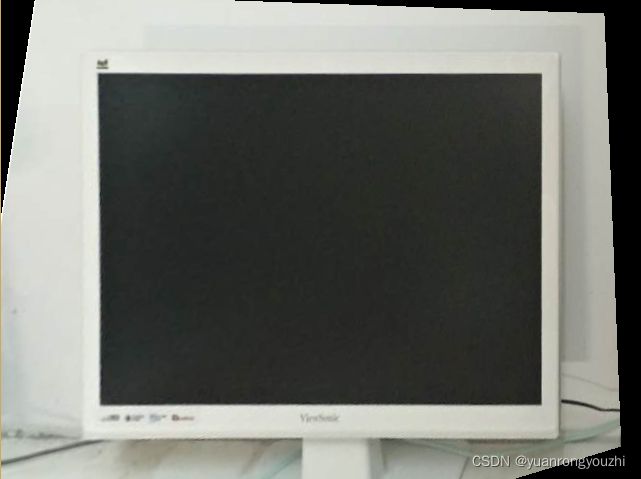
下图中的显示器为畸形,我们通过投影变换将显示器校正。

代码如下:
*关闭当前显示窗口,清空屏幕
dev_close_window ()
*读取测试图像
read_image (Image_display, 'display')
*将图像转化为灰度图像
rgb1_to_gray (Image_display, GrayImage)
*获取图像的尺寸
get_image_size(Image_display,imageWidth, imageHeight)
*新建显示窗口,适应图像尺寸
dev_open_window (0, 0, imageWidth, imageHeight, 'black', WindowHandle1)
dev_display (GrayImage)
*初始化角点坐标
XCoordCorners := []
YCoordCorners := []
*阈值处理,提取较暗的区域
threshold(GrayImage,DarkRegion,0, 80)
*分离不相连的区域
connection (DarkRegion, ConnectedRegions)
*选择面积最大的暗色区域,即屏幕区域
select_shape_std (ConnectedRegions, displayRegion, 'max_area', 70)
*裁剪屏幕区域
reduce_domain (GrayImage, displayRegion, displayImage)
*创建边缘轮廓
gen_contour_region_xld (displayRegion, Contours, 'border')
*将轮廓分割为边
segment_contours_xld (Contours, ContoursSplit, 'lines', 5, 4, 2)
*获取边的数量
count_obj (ContoursSplit, Number)
*存储每条边的起点位置
for index:=1 to Number by 1
   select_obj(ContoursSplit, ObjectCurrent, index)
   *拟合每条边
   fit_line_contour_xld (ObjectCurrent, 'tukey', -1, 0, 5, 2, RowBegin, ColBegin, RowEnd, ColEnd, Nr, Nc, Dist)
   *存储每条边的顶点x坐标
   tuple_concat (XCoordCorners, RowBegin, XCoordCorners)
   *存储每条边的顶点y坐标
   tuple_concat (YCoordCorners, ColBegin, YCoordCorners)
endfor

* 投影变换给四个特征点与校正后的坐标建立关联
XOff:= 100
YOff:= 100*imageHeight/imageWidth
hom_vector_to_proj_hom_mat2d (XCoordCorners, YCoordCorners, [1,1,1,1], [YOff,YOff,imageHeight-YOff,imageHeight-YOff], [XOff,imageWidth-XOff,imageWidth-XOff,XOff], [1,1,1,1], 'normalized_dlt', HomMat2D)
*投影变换
projective_trans_image (Image_display, Image_rectified, HomMat2D, 'bilinear', 'false', 'false')
* 显示校正结果
dev_display (Image_rectified)
代码中的“[]”为Tuple类型,这里可以理解为包含4个实数值的数组。“XCoordCorners := []”和“YCoordCorners := []”这两个数组中,分别存储了轮廓4个顶点的X坐标和Y坐标。代码中用到了for循环,Halcon中的for循环语法如下:
for(Index := StartNumber to EndNumber by Step)
循环的语句
endfor
投影变换矩阵:hom_vector_to_proj_hom_mat2d (XCoordCorners, YCoordCorners, [1,1,1,1], [YOff,YOff,imageHeight-YOff,imageHeight-YOff], [XOff,imageWidth-XOff,imageWidth-XOff,XOff], [1,1,1,1], ‘normalized_dlt’, HomMat2D)中的“[YOff,YOff,imageHeight-YOff,imageHeight-YOff], [XOff,imageWidth-XOff,imageWidth-XOff,XOff],”可以根据自己需要设置,但是为了保持显示器的纵横比不失真,某个坐标更改后,其他与之关联的坐标也要更改。
最终结果如下图。

总结
相比其他内容,图像的校正与变换涉及到几何学知识,比较难懂一点,要多花些功夫研究。在网上我也看到有把仿射变换和投影变换混为一谈的,这其实是概念问题,要多加明晰。
参考文章:
1.为什么要引入齐次坐标