OpenCV-Calibration-Detailed Description翻译
OpenCV Calibration-Detailed Description
前言
看了众多关于针孔相机模型的介绍和相关矩阵变换的推导Blog,回头发现在OpenCV同样有相关内容,并且描述的相当清晰。于是工作之便,作以翻译分享。
翻译采用了一段英文原文接一段翻译的形式,只一小部分专业英语尚未翻译,中英文对照见下表。
| 英文 | 语境 | 中文 |
|---|---|---|
| pinhole | pinhole camera model | 针孔相机模型 |
| perspective | perspective transformation | 透视变换 |
| image plane | 图像平面 | |
| project | 投影 | |
| homogeneous | homogeneous coordinates | 齐次坐标 |
| system of coordinates | 坐标系 | |
| intrinsic | intrinsic camera matrix | 相机内参矩阵 |
| rotation | 旋转 | |
| translation | 平移 | |
| focal | focal length | 焦距 |
| view | scene viewed | 场景视图 |
| principal point | 光轴点 | |
| zoom len | 变焦镜头 | |
| scale | 缩放 | |
| extrinsic parameters | 外参 | |
| basis | 基底 | |
| distortion | radial distrotion | 径向畸变 |
| distortion | tangential distortion | 切向畸变 |
| thin prism distortion coefficients | 薄透镜畸变系数 | |
| barrel distortion | 桶形畸变 | |
| monotonically | monotonically decreasing | 单调递减 |
| pincushion distortion | 枕型畸变 | |
| particle image velocimetry | 粒子图像测速 | |
| triangulation with a laser fan | 激光三角测量 | |
| calibration pattern | 标定模板 | |
| camera optical axes parallel | 相机光轴平行/平行校正 | |
| affine transformations | 仿射变换 | |
| cartesian vector | 笛卡尔向量 |
坐标系变换
The functions in this section use a so-called pinhole camera model. The view of a scene is obtained by projecting a scene’s 3D point P w P_w Pw into the image plane using a perspective transformation which forms the corresponding pixel p p p. Both P w P_w Pw and p p p are represented in homogeneous coordinates, i.e. as 3D and 2D homogeneous vector respectively. You will find a brief introduction to projective geometry, homogeneous vectors and homogeneous transformations at the end of this section’s introduction. For more succinct notation, we often drop the ‘homogeneous’ and say vector instead of homogeneous vector.
本章节中的函数使用了针孔相机模型。一种场景是使用透视变换,将三维空间的坐标点 P w P_w Pw 投影到图像平面的对应点 p p p。 P w P_w Pw 与 p p p均使用齐次坐标表示,则分别对应3D和2D的齐次向量。在本节介绍的最后,你会看到关于投影几何,、齐次向量、齐次变换的简要介绍。为了更简要的表示,我们省略“齐次”直接说向量而不是齐次向量。
The distortion-free projective transformation given by a pinhole camera model is shown below.
在针孔相机模型中,无畸变的投影变换如下所示。
[ s p = A [ R ∣ t ] P w ] , [s \; p = A \begin{bmatrix} R|t \end{bmatrix} P_w], [sp=A[R∣t]Pw],
where P w P_w Pw is a 3D point expressed with respect to the world coordinate system, p p p is a 2D pixel in the image plane, A A A is the intrinsic camera matrix, R R R and t t t are the rotation and translation that describe the change of coordinates from world to camera coordinate systems (or camera frame) and s s s is the projective transformation’s arbitrary scaling and not part of the camera model.
其中, P w P_w Pw表示世界坐标系中的3D点。 p p p是图像平面中的2D点。 A A A是相机内参矩阵。 R R R和 t t t分别表示坐标点从世界坐标系至相机坐标系(或被称为camera frame)的旋转和平移。 s s s表示任意缩放的投影变换,不属于相机模型。
The intrinsic camera matrix A A A (notation used as in Zhengyou Zhang and also generally notated as K K K) projects 3D points given in the camera coordinate system to 2D pixel coordinates, i.e.
相机内参矩阵 A A A(在Zhengyou Zhang中被使用,也被记为 K K K)将相机坐标系中的3D点投影至2D像素坐标。
p = A P c . p = A P_c. p=APc.
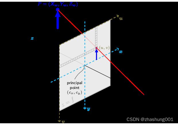
The camera matrix A A A is composed of the focal lengths f x f_x fx and f y f_y fy, which are expressed in pixel units, and the principal point ( c x , c y ) (c_x, c_y) (cx,cy), that is usually close to the image center:
相机矩阵 A A A包括:焦距 f x f_x fx和 f y f_y fy,以像素为单位。光轴点 ( c x , c y ) (c_x, c_y) (cx,cy)通常表示为图像中心。
A = [ f x 0 c x 0 f y c y 0 0 1 ] , A = \begin{bmatrix}{f_x}&{0}&{c_x}\\{0}&{f_y}&{c_y}\\{0}&{0}&{1}\end{bmatrix}, A=⎣ ⎡fx000fy0cxcy1⎦ ⎤,
and thus
s [ u v 1 ] = [ f x 0 c x 0 f y c y 0 0 1 ] [ X c Y c Z c ] . s \begin{bmatrix}{u}\\{v}\\{1}\end{bmatrix} = \begin{bmatrix}{f_x}&{0}&{c_x}\\{0}&{f_y}&{c_y}\\{0}&{0}&{1}\end{bmatrix} \begin{bmatrix}{X_c}\\{Y_c}\\{Z_c}\end{bmatrix}. s⎣ ⎡uv1⎦ ⎤=⎣ ⎡fx000fy0cxcy1⎦ ⎤⎣ ⎡XcYcZc⎦ ⎤.
The matrix of intrinsic parameters does not depend on the scene viewed. So, once estimated, it can be re-used as long as the focal length is fixed (in case of a zoom lens). Thus, if an image from the camera is scaled by a factor, all of these parameters need to be scaled (multiplied/divided, respectively) by the same factor.
相机内参矩阵中的参数不由视图决定。因此,一次估算,只要焦距固定(除了变焦镜头)便可以一直使用。因此如果图像发生缩放,所有的参数同样需要缩放(对应乘或者除)相同的系数即可。
The joint rotation-translation matrix [ R ∣ t ] [R|t] [R∣t] is the matrix product of a projective transformation and a homogeneous transformation. The 3-by-4 projective transformation maps 3D points represented in camera coordinates to 2D poins in the image plane and represented in normalized camera coordinates x ′ = X c / Z c x' = X_c / Z_c x′=Xc/Zc and y ′ = Y c / Z c y' = Y_c / Z_c y′=Yc/Zc:
联合旋转平移矩阵 [ R ∣ t ] [R|t] [R∣t] 是投影变换和齐次变换的矩阵乘法。其中3×4 大小的投影变换将相机坐标的一个3D点映射到图像平面的2D点。并使用归一化相机坐标表示 x ′ = X c / Z c x' = X_c / Z_c x′=Xc/Zc, y ′ = Y c / Z c y' = Y_c / Z_c y′=Yc/Zc。
Z c [ x ′ y ′ 1 ] = [ 1 0 0 0 0 1 0 0 0 0 1 0 ] [ X c Y c Z c 1 ] . Z_c \begin{bmatrix} x' \\ y' \\ 1\end{bmatrix} = \begin{bmatrix}1 & 0 & 0 & 0 \\0 & 1 & 0 & 0 \\0 & 0 & 1 & 0\end{bmatrix} \begin{bmatrix} X_c \\ Y_c \\ Z_c \\ 1\end{bmatrix}. Zc⎣ ⎡x′y′1⎦ ⎤=⎣ ⎡100010001000⎦ ⎤⎣ ⎡XcYcZc1⎦ ⎤.
The homogeneous transformation is encoded by the extrinsic parameters R R R and t t t and represents the change of basis from world coordinate system w w w to the camera coordinate sytem c c c. Thus, given the representation of the point P P P in world coordinates, P w P_w Pw, we obtain P P P’s representation in the camera coordinate system, P c P_c Pc, by
齐次变换包括外参 R R R 和 t t t,它表示基底从世界坐标系 w w w到相机坐标系 c c c。即给出点 P P P在世界坐标的坐标 P w P_w Pw,通过该矩阵计算可与获得点 P P P在相机坐标的对应点 P c P_c Pc。
[ P c = [ R t 0 1 ] P w ] , [P_c = \begin{bmatrix} R & t \\ 0 & 1 \end{bmatrix} P_w], [Pc=[R0t1]Pw],
This homogeneous transformation is composed out of R R R, a 3-by-3 rotation matrix, and t t t, a 3-by-1 translation vector:
该齐次变换由3×3旋转矩阵 R R R和3×1平移向量 t t t组成。
[ R t 0 1 ] = [ r 11 r 12 r 13 t x r 21 r 22 r 23 t y r 31 r 32 r 33 t z 0 0 0 1 ] , \begin{bmatrix} R & t \\ 0 & 1 \end{bmatrix} = \begin{bmatrix}r_{11} & r_{12} & r_{13} & t_x \\r_{21} & r_{22} & r_{23} & t_y \\r_{31} & r_{32} & r_{33} & t_z \\0 & 0 & 0 & 1\end{bmatrix}, [R0t1]=⎣ ⎡r11r21r310r12r22r320r13r23r330txtytz1⎦ ⎤,
and therefore
[ X c Y c Z c 1 ] = [ r 11 r 12 r 13 t x r 21 r 22 r 23 t y r 31 r 32 r 33 t z 0 0 0 1 ] [ X w Y w Z w 1 ] . \begin{bmatrix} X_c \\ Y_c \\ Z_c \\ 1 \end{bmatrix} = \begin{bmatrix} r_{11} & r_{12} & r_{13} & t_x \\ r_{21} & r_{22} & r_{23} & t_y \\ r_{31} & r_{32} & r_{33} & t_z \\ 0 & 0 & 0 & 1 \end{bmatrix} \begin{bmatrix} X_w \\ Y_w \\ Z_w \\ 1 \end{bmatrix}. ⎣ ⎡XcYcZc1⎦ ⎤=⎣ ⎡r11r21r310r12r22r320r13r23r330txtytz1⎦ ⎤⎣ ⎡XwYwZw1⎦ ⎤.
Combining the projective transformation and the homogeneous transformation, we obtain the projective transformation that maps 3D points in world coordinates into 2D points in the image plane and in normalized camera coordinates:
合并投影变换和齐次变换,我们可以获得(另一个)投影变换,使用该矩阵可以将世界坐标的3D点映射到图像平面2D点或归一化相机坐标。
Z c [ x ′ y ′ 1 ] = [ R ∣ t ] [ X w Y w Z w 1 ] = [ r 11 r 12 r 13 t x r 21 r 22 r 23 t y r 31 r 32 r 33 t z ] [ X w Y w Z w 1 ] , Z_c \begin{bmatrix} x' \\ y' \\ 1\end{bmatrix} = \begin{bmatrix} R|t \end{bmatrix} \begin{bmatrix}X_w \\ Y_w \\ Z_w \\ 1\end{bmatrix} = \begin{bmatrix} r_{11} & r_{12} & r_{13} & t_x \\ r_{21} & r_{22} & r_{23} & t_y \\ r_{31} & r_{32} & r_{33} & t_z \end{bmatrix} \begin{bmatrix} X_w \\ Y_w \\ Z_w \\ 1 \end{bmatrix}, Zc⎣ ⎡x′y′1⎦ ⎤=[R∣t]⎣ ⎡XwYwZw1⎦ ⎤=⎣ ⎡r11r21r31r12r22r32r13r23r33txtytz⎦ ⎤⎣ ⎡XwYwZw1⎦ ⎤,
with x ′ = X c / Z c x' = X_c / Z_c x′=Xc/Zc and y ′ = Y c / Z c y' = Y_c / Z_c y′=Yc/Zc. Putting the equations for instrincs and extrinsics together, we can write out
$ s ; p = A \begin{bmatrix} R|t \end{bmatrix} P_w $ as
使用 x ′ = X c / Z c x' = X_c / Z_c x′=Xc/Zc 和 y ′ = Y c / Z c y' = Y_c / Z_c y′=Yc/Zc,将内参和外参带入,我们可以得到 s p = A [ R ∣ t ] P w s \; p = A \begin{bmatrix} R|t \end{bmatrix} P_w sp=A[R∣t]Pw。
s [ u v 1 ] = [ f x 0 c x 0 f y c y 0 0 1 ] [ r 11 r 12 r 13 t x r 21 r 22 r 23 t y r 31 r 32 r 33 t z ] [ X w Y w Z w 1 ] . s \begin{bmatrix}{u}\\{v}\\{1}\end{bmatrix} = \begin{bmatrix}{f_x}&{0}&{c_x}\\{0}&{f_y}&{c_y}\\{0}&{0}&{1}\end{bmatrix} \begin{bmatrix} r_{11} & r_{12} & r_{13} & t_x \\ r_{21} & r_{22} & r_{23} & t_y \\ r_{31} & r_{32} & r_{33} & t_z \end{bmatrix} \begin{bmatrix} X_w \\ Y_w \\ Z_w \\ 1 \end{bmatrix}. s⎣ ⎡uv1⎦ ⎤=⎣ ⎡fx000fy0cxcy1⎦ ⎤⎣ ⎡r11r21r31r12r22r32r13r23r33txtytz⎦ ⎤⎣ ⎡XwYwZw1⎦ ⎤.
If Z c ≠ 0 Z_c \ne 0 Zc=0, the transformation above is equivalent to the following,
假设 Z c ≠ 0 Z_c \ne 0 Zc=0,上述变换可等价于以下公式
[ u v ] = [ f x X c / Z c + c x f y Y c / Z c + c y ] \begin{bmatrix} u \\ v \end{bmatrix} = \begin{bmatrix} f_x X_c/Z_c + c_x \\ f_y Y_c/Z_c + c_y \end{bmatrix} [uv]=[fxXc/Zc+cxfyYc/Zc+cy]
with
[ X c Y c Z c ] = [ R ∣ t ] [ X w Y w Z w 1 ] . \begin{bmatrix}{X_c}\\{Y_c}\\{Z_c}\end{bmatrix} = \begin{bmatrix} R|t \end{bmatrix} \begin{bmatrix} X_w \\ Y_w \\ Z_w \\ 1 \end{bmatrix}. ⎣ ⎡XcYcZc⎦ ⎤=[R∣t]⎣ ⎡XwYwZw1⎦ ⎤.
The following figure illustrates the pinhole camera model.
如下图描述了针孔相机模型
相机畸变模型
Real lenses usually have some distortion, mostly radial distortion, and slight tangential distortion. So, the above model is extended as:
真实的镜头通常存在一定畸变,通常是径向畸变和轻微切向畸变。因此上述模型扩展为:
[ u v ] = [ f x x ′ ′ + c x f y y ′ ′ + c y ] \begin{bmatrix} u \\ v\end{bmatrix} = \begin{bmatrix}f_x x'' + c_x \\f_y y'' + c_y\end{bmatrix} [uv]=[fxx′′+cxfyy′′+cy]
where
[ x ′ ′ y ′ ′ ] = [ x ′ 1 + k 1 r 2 + k 2 r 4 + k 3 r 6 1 + k 4 r 2 + k 5 r 4 + k 6 r 6 + 2 p 1 x ′ y ′ + p 2 ( r 2 + 2 x ′ 2 ) + s 1 r 2 + s 2 r 4 y ′ 1 + k 1 r 2 + k 2 r 4 + k 3 r 6 1 + k 4 r 2 + k 5 r 4 + k 6 r 6 + p 1 ( r 2 + 2 y ′ 2 ) + 2 p 2 x ′ y ′ + s 3 r 2 + s 4 r 4 ] \begin{bmatrix} x'' \\ y''\end{bmatrix} = \begin{bmatrix} x' \frac{1 + k_1 r^2 + k_2 r^4 + k_3 r^6}{1 + k_4 r^2 + k_5 r^4 + k_6 r^6} + 2 p_1 x' y' + p_2(r^2 + 2 x'^2) + s_1 r^2 + s_2 r^4 \\ y' \frac{1 + k_1 r^2 + k_2 r^4 + k_3 r^6}{1 + k_4 r^2 + k_5 r^4 + k_6 r^6} + p_1 (r^2 + 2 y'^2) + 2 p_2 x' y' + s_3 r^2 + s_4 r^4 \\ \end{bmatrix} [x′′y′′]=[x′1+k4r2+k5r4+k6r61+k1r2+k2r4+k3r6+2p1x′y′+p2(r2+2x′2)+s1r2+s2r4y′1+k4r2+k5r4+k6r61+k1r2+k2r4+k3r6+p1(r2+2y′2)+2p2x′y′+s3r2+s4r4]
with
r 2 = x ′ 2 + y ′ 2 r^2 = x'^2 + y'^2 r2=x′2+y′2
and
[ x ′ y ′ ] = [ X c / Z c Y c / Z c ] , \begin{bmatrix} x'\\ y'\end{bmatrix} = \begin{bmatrix}X_c/Z_c \\ Y_c/Z_c\end{bmatrix}, [x′y′]=[Xc/ZcYc/Zc],
if Z c ≠ 0 Z_c \ne 0 Zc=0.
The distortion parameters are the radial coefficients k 1 k_1 k1, k 2 k_2 k2, k 3 k_3 k3, k 4 k_4 k4, k 5 k_5 k5, and k 6 k_6 k6 , p 1 p_1 p1 and p 2 p_2 p2 are the tangential distortion coefficients, and s 1 s_1 s1, s 2 s_2 s2, s 3 s_3 s3, and s 4 s_4 s4, are the thin prism distortion coefficients. Higher-order coefficients are not considered in OpenCV.
畸变参数中: k 1 k_1 k1、 k 2 k_2 k2、 k 3 k_3 k3、 k 4 k_4 k4、 k 5 k_5 k5、 k 6 k_6 k6为径向畸变系数, p 1 p_1 p1 、 p 2 p_2 p2是切向畸变系数, s 1 s_1 s1、 s 2 s_2 s2、 s 3 s_3 s3、 s 4 s_4 s4是薄透镜畸变系数,OpenCV中不考虑更高阶系数。
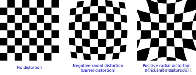
The next figures show two common types of radial distortion: barrel distortion ( 1 + k 1 r 2 + k 2 r 4 + k 3 r 6 1 + k_1 r^2 + k_2 r^4 + k_3 r^6 1+k1r2+k2r4+k3r6 monotonically decreasing) and pincushion distortion ( 1 + k 1 r 2 + k 2 r 4 + k 3 r 6 1 + k_1 r^2 + k_2 r^4 + k_3 r^6 1+k1r2+k2r4+k3r6 monotonically increasing).Radial distortion is always monotonic for real lenses, and if the estimator produces a non-monotonic result, this should be considered a calibration failure. More generally, radial distortion must be monotonic and the distortion function must be bijective. A failed estimation result may look deceptively good near the image center but will work poorly in e.g. AR/SFM applications. The optimization method used in OpenCV camera calibration does not include these constraints as the framework does not support the required integer programming and polynomial inequalities. See issue #15992 for additional information.
如下两张图像分别展示了两种常见方式的径向畸变:桶形畸变 (当 1 + k 1 r 2 + k 2 r 4 + k 3 r 6 1 + k_1 r^2 + k_2 r^4 + k_3 r^6 1+k1r2+k2r4+k3r6 单点递减) 枕型畸变 (当 1 + k 1 r 2 + k 2 r 4 + k 3 r 6 1 + k_1 r^2 + k_2 r^4 + k_3 r^6 1+k1r2+k2r4+k3r6 单调递增)。对于实际的镜头,径向畸变往往是单调的。如估算得到了非单调的结果,应该被视为标定失败。更一般的说,径向畸变必须是单调的而且畸变函数必须是bijective的。一个失败的估算结果可能在图像中心附近表现良好,但是在AR/SFM等应用时则很糟糕。在OpenCV的相机标定中实现的优化方法并不包括该项约束,因为框架不支持integer programming和polynomial inequalities。在issue #15992中查看更多信息。

In some cases, the image sensor may be tilted in order to focus an oblique plane in front of the camera (Scheimpflug principle). This can be useful for particle image velocimetry (PIV) or triangulation with a laser fan. The tilt causes a perspective distortion of x ′ ′ x'' x′′ and y ′ ′ y'' y′′. This distortion can be modeled in the following way, see e.g. @cite Louhichi07.
在有些情况,成像传感器可能会倾斜的为了聚焦一个斜面(Scheimpflug principle)。这种场景在粒子图像测速(PIV)或者激光三角测量中很有帮助。这种畸变可以使用Louhichi中的模型。
[ u v ] = [ f x x ′ ′ ′ + c x f y y ′ ′ ′ + c y ] , \begin{bmatrix} u \\ v \end{bmatrix} = \begin{bmatrix}f_x x''' + c_x \\f_y y''' + c_y\end{bmatrix}, [uv]=[fxx′′′+cxfyy′′′+cy],
where
s [ x ′ ′ ′ y ′ ′ ′ 1 ] = [ R 33 ( τ x , τ y ) 0 − R 13 ( τ x , τ y ) 0 R 33 ( τ x , τ y ) − R 23 ( τ x , τ y ) 0 0 1 ] R ( τ x , τ y ) [ x ′ ′ y ′ ′ 1 ] s\begin{bmatrix}{x'''}\\{y'''}\\{1} \end{bmatrix}= \begin{bmatrix}{R_{33}(\tau_x, \tau_y)}&{0}&{-R_{13}(\tau_x, \tau_y)}\\ {0}&{R_{33}(\tau_x, \tau_y)}&{-R_{23}(\tau_x, \tau_y)} \\{0}&{0}&{1}\end{bmatrix} R(\tau_x, \tau_y) \begin{bmatrix}{x''}\\{y''}\\{1}\end{bmatrix} s⎣ ⎡x′′′y′′′1⎦ ⎤=⎣ ⎡R33(τx,τy)000R33(τx,τy)0−R13(τx,τy)−R23(τx,τy)1⎦ ⎤R(τx,τy)⎣ ⎡x′′y′′1⎦ ⎤
and the matrix R ( τ x , τ y ) R(\tau_x, \tau_y) R(τx,τy) is defined by two rotations with angular parameter τ x \tau_x τx and τ y \tau_y τy, respectively,
矩阵 R ( τ x , τ y ) R(\tau_x, \tau_y) R(τx,τy) 中的两个旋转分别包括 τ x \tau_x τx和 τ y \tau_y τy两个角度参数。
R ( τ x , τ y ) = [ cos ( τ y ) 0 − sin ( τ y ) 0 1 0 sin ( τ y ) 0 cos ( τ y ) ] [ 1 0 0 0 cos ( τ x ) sin ( τ x ) 0 − sin ( τ x ) cos ( τ x ) ] = [ cos ( τ y ) sin ( τ y ) sin ( τ x ) − sin ( τ y ) cos ( τ x ) 0 cos ( τ x ) sin ( τ x ) sin ( τ y ) − cos ( τ y ) sin ( τ x ) cos ( τ y ) cos ( τ x ) ] . R(\tau_x, \tau_y) = \begin{bmatrix}{\cos(\tau_y)}&{0}&{-\sin(\tau_y)}\\{0}&{1}&{0}\\{\sin(\tau_y)}&{0}&{\cos(\tau_y)}\end{bmatrix} \begin{bmatrix}{1}&{0}&{0}\\{0}&{\cos(\tau_x)}&{\sin(\tau_x)}\\{0}&{-\sin(\tau_x)}&{\cos(\tau_x)}\end{bmatrix} = \begin{bmatrix}{\cos(\tau_y)}&{\sin(\tau_y)\sin(\tau_x)}&{-\sin(\tau_y)\cos(\tau_x)} \\{0}&{\cos(\tau_x)}&{\sin(\tau_x)}\\ {\sin(\tau_y)}&{-\cos(\tau_y)\sin(\tau_x)}&{\cos(\tau_y)\cos(\tau_x)}\end{bmatrix}. R(τx,τy)=⎣ ⎡cos(τy)0sin(τy)010−sin(τy)0cos(τy)⎦ ⎤⎣ ⎡1000cos(τx)−sin(τx)0sin(τx)cos(τx)⎦ ⎤=⎣ ⎡cos(τy)0sin(τy)sin(τy)sin(τx)cos(τx)−cos(τy)sin(τx)−sin(τy)cos(τx)sin(τx)cos(τy)cos(τx)⎦ ⎤.
In the functions below the coefficients are passed or returned as
在如下的函数中,对应的输出输出的系数向量为:
( k 1 , k 2 , p 1 , p 2 [ , k 3 [ , k 4 , k 5 , k 6 [ , s 1 , s 2 , s 3 , s 4 [ , τ x , τ y ] ] ] ] ) (k_1, k_2, p_1, p_2[, k_3[, k_4, k_5, k_6 [, s_1, s_2, s_3, s_4[, \tau_x, \tau_y]]]]) (k1,k2,p1,p2[,k3[,k4,k5,k6[,s1,s2,s3,s4[,τx,τy]]]])
vector. That is, if the vector contains four elements, it means that k 3 = 0 k_3=0 k3=0. The distortion coefficients do not depend on the scene viewed. Thus, they also belong to the intrinsic camera parameters. And they remain the same regardless of the captured image resolution. If, for example, a camera has been calibrated on images of 320 x 240 resolution, absolutely the same distortion coefficients can be used for 640 x 480 images from the same camera while f x f_x fx, f y f_y fy, c x c_x cx, and c y c_y cy need to be scaled appropriately.
如果向量包括四个元素,则 k 3 = 0 k_3=0 k3=0。畸变矩阵与场景视图无关,仍然属于相机内参,这些参数与图像分辨率无关。比如,对于同一个相机在320 x 240 分辨率中的标定的畸变系数结果与640 x 480 分辨率的一致,只需要适当缩放 f x f_x fx, f y f_y fy, c x c_x cx, and c y c_y cy。
The functions below use the above model to do the following:
使用上述模型,以下的函数主要实现以下功能:
-
Project 3D points to the image plane given intrinsic and extrinsic parameters.
-
通过给定的内外参,将3D点投影到图像平面。
-
Compute extrinsic parameters given intrinsic parameters, a few 3D points, and their projections.
-
???
-
Estimate intrinsic and extrinsic camera parameters from several views of a known calibration pattern (every view is described by several 3D-2D point correspondences).
-
使用多个视图对应的标定模板(每一视图由多个3D-2D的点对描述)估算相机内外参。
-
Estimate the relative position and orientation of the stereo camera “heads” and compute the rectification transformation that makes the camera optical axes parallel.
-
估算多相机"heads"的相对位置和方位。计算rectification transformation 使得 平行校正。
Homogeneous Coordinates
Homogeneous Coordinates are a system of coordinates that are used in projective geometry. Their use allows to represent points at infinity by finite coordinates and simplifies formulas when compared to the cartesian counterparts, e.g. they have the advantage that affine transformations can be expressed as linear homogeneous transformation.
齐次坐标是在投影几何中使用的坐标系,被用来使用有限坐标来表示无限的点。相比cartesian counterparts可以简化公式。比如,将仿射变换表示为线性齐次变换。
One obtains the homogeneous vector P h P_h Ph by appending a 1 along an n-dimensional cartesian vector P P P e.g. for a 3D cartesian vector the mapping P → P h P \rightarrow P_h P→Ph is:
对于n维笛卡尔向量 P P P,我们可以通过在后面添加一个1来获得齐次向量 P h P_h Ph。比如,对于3D笛卡尔向量,映射 P → P h P \rightarrow P_h P→Ph可以表示为:
[ X Y Z ] → [ X Y Z 1 ] . \begin{bmatrix} X \\ Y \\ Z\end{bmatrix} \rightarrow \begin{bmatrix} X \\ Y \\ Z \\ 1\end{bmatrix}. ⎣ ⎡XYZ⎦ ⎤→⎣ ⎡XYZ1⎦ ⎤.
For the inverse mapping P h → P P_h \rightarrow P Ph→P, one divides all elements of the homogeneous vector by its last element, e.g. for a 3D homogeneous vector one gets its 2D cartesian counterpart by:
对于 P h → P P_h \rightarrow P Ph→P 反向映射,使用最后一个元素除以齐次向量的所有元素,对于一个三位齐次向量获取其对应二维笛卡尔向量如下:
[ X Y W ] → [ X / W Y / W ] , \begin{bmatrix} X \\ Y \\ W\end{bmatrix} \rightarrow \begin{bmatrix}X / W \\ Y / W \end{bmatrix}, ⎣ ⎡XYW⎦ ⎤→[X/WY/W],
if W ≠ 0 W \ne 0 W=0.
Due to this mapping, all multiples k P h k P_h kPh, for k ≠ 0 k \ne 0 k=0, of a homogeneous point represent the same point P h P_h Ph. An intuitive understanding of this property is that under a projective transformation, all multiples of P h P_h Ph are mapped to the same point. This is the physical observation one does for pinhole cameras, as all points along a ray through the camera’s pinhole are projected to the same image point, e.g. all points along the red ray in the image of the pinhole camera model above would be mapped to the same image coordinate. This property is also the source for the scale ambiguity s in the equation of the pinhole camera model.
因为这个映射,当 k ≠ 0 k \ne 0 k=0时,对于不同倍数的齐次(坐标)点 k P h k P_h kPh,与 P h P_h Ph实际为同一个点。在投影变换中可以更直观的理解:不同倍数的 P h P_h Ph都会映射到同一个点。对于针孔相机,通过物理观察,射线上所有的通过小孔的点都投影到图像中同一个点。比如,在针孔相机模型的图片中,红色射线的所有点都将映射到相同图像坐标。这一特性也造成了针孔相机模型中scale ambiguity。
As mentioned, by using homogeneous coordinates we can express any change of basis parameterized by R R R and t t t as a linear transformation, e.g. for the change of basis from coordinate system 0 to coordinate system 1 becomes:
如前所述,使用齐次坐标,我们可以将 R R R和 t t t参数化为一种基底变换的线性变换。比如将基底从坐标系 0到坐标系 1。
P 1 = R P 0 + t → P h 1 = [ R t 0 1 ] P h 0 . P_1 = R P_0 + t \rightarrow P_{h_1} = \begin{bmatrix}R & t \\ 0 & 1 \end{bmatrix} P_{h_0}. P1=RP0+t→Ph1=[R0t1]Ph0.