数据增强,对图片的crop,以及对关键点标注的对应缩放
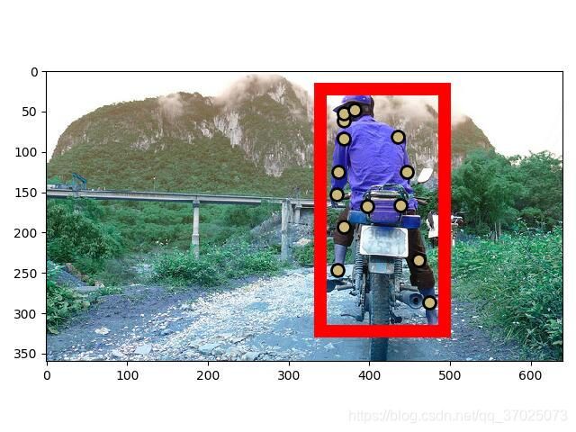
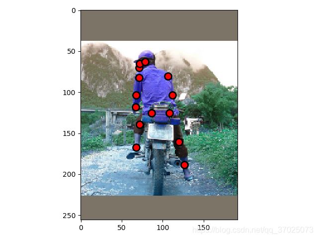
以以下图片(000000391895.jpg)为例子,可视化图片裁剪过程
对图片裁剪的关键在于如何让关键点标注在裁剪前后同步进行坐标点的转换。要裁剪的区域为gt_box,但需要对gt_box进行一定的扩展,首先算出中心点objcenter,再根据中心点进行高和宽的缩放,然后对图片进行一定的裁剪。
其实我还是有点没搞懂代码,为什么有个crop_size和min_shape出来。
详细可参考此博客


if __name__ == '__main__':
    import matplotlib.patches as patches


    def augmentationCropImage(img, bbox, joints=None):
        is_train = True
        height, width = 256, 192
        bbox = np.array(bbox).reshape(4, ).astype(np.float32)
        add = max(img.shape[0], img.shape[1])
        mean_value = np.array([122.7717, 115.9465, 102.9801])
        bimg = cv2.copyMakeBorder(img, add, add, add, add, borderType=cv2.BORDER_CONSTANT, value=mean_value.tolist())
        objcenter = np.array([(bbox[0] + bbox[2]) / 2., (bbox[1] + bbox[3]) / 2.])
        bbox += add
        objcenter += add
        if is_train:
            joints[:, :2] += add
            inds = np.where(joints[:, -1] == 0)
            joints[inds, :2] = -1000000  # avoid influencing by data processing
        crop_width = (bbox[2] - bbox[0]) * (1 + 0.1 * 2)
        crop_height = (bbox[3] - bbox[1]) * (1 + 0.15 * 2)
        if is_train:
            crop_width = crop_width * (1 + 0.25)
            crop_height = crop_height * (1 + 0.25)
        if crop_height / height > crop_width / width:
            crop_size = crop_height
            min_shape = height
        else:
            crop_size = crop_width
            min_shape = width

        crop_size = min(crop_size, objcenter[0] / width * min_shape * 2. - 1.)
        crop_size = min(crop_size, (bimg.shape[1] - objcenter[0]) / width * min_shape * 2. - 1)
        crop_size = min(crop_size, objcenter[1] / height * min_shape * 2. - 1.)
        crop_size = min(crop_size, (bimg.shape[0] - objcenter[1]) / height * min_shape * 2. - 1)

        min_x = int(objcenter[0] - crop_size / 2. / min_shape * width)
        max_x = int(objcenter[0] + crop_size / 2. / min_shape * width)
        min_y = int(objcenter[1] - crop_size / 2. / min_shape * height)
        max_y = int(objcenter[1] + crop_size / 2. / min_shape * height)

        x_ratio = float(width) / (max_x - min_x)
        y_ratio = float(height) / (max_y - min_y)

        if is_train:
            joints[:, 0] = joints[:, 0] - min_x
            joints[:, 1] = joints[:, 1] - min_y

            joints[:, 0] *= x_ratio
            joints[:, 1] *= y_ratio
            label = joints[:, :2].copy()
            valid = joints[:, 2].copy()

        img = cv2.resize(bimg[min_y:max_y, min_x:max_x, :], (width, height))
        details = np.asarray([min_x - add, min_y - add, max_x - add, max_y - add]).astype(np.float)

        if is_train:
            return img, joints, details
        else:
            return img, details


    num_class = 17
    a =  {'unit': {'num_keypoints': 14, 'keypoints': [368, 61, 1, 369, 52, 2, 0, 0, 0, 382, 48, 2, 0, 0, 0, 368, 84, 2, 435, 81, 2, 362, 125, 2, 446, 125, 2, 360, 153, 2, 0, 0, 0, 397, 167, 1, 439, 166, 1, 369, 193, 2, 461, 234, 2, 361, 246, 2, 474, 287, 2], 'GT_bbox': [339, 22, 493, 322]}, 'imgInfo': {'imgID': 391895, 'img_paths': '000000391895.jpg'}, 'operation': 0}
    image_name = a['imgInfo']['img_paths']
    points = np.array(a['unit']['keypoints']).reshape(num_class, 3).astype(np.float32)
    gt_bbox = a['unit']['GT_bbox']
    points = points.flatten()
    x = points[0::3]
    y = points[1::3]
    v = points[2::3]
    plt.figure()
    c = (np.random.random((1, 3)) * 0.6 + 0.4).tolist()[0]
    plt.plot(x[v > 0], y[v > 0], 'o', markersize=10, markerfacecolor=c, markeredgecolor='k', markeredgewidth=2)

    x = gt_bbox[0]
    y = gt_bbox[1]
    width = gt_bbox[2] - gt_bbox[0]
    height = gt_bbox[3] - gt_bbox[1]
    currentAxis = plt.gca()
    rect = patches.Rectangle((x, y), width, height, linewidth=10, edgecolor='r', facecolor='none')
    currentAxis.add_patch(rect)
    img =  cv2.imread(image_name)

    plt.imshow(img)
    plt.show()


    points = np.array(a['unit']['keypoints']).reshape(num_class, 3).astype(np.float32)
    image, points, details = augmentationCropImage(img, gt_bbox, points)


    # 画矩形
    x = details[0]
    y = details[1]
    width = details[2] - details[0]
    height = details[3] - details[1]
    currentAxis = plt.gca()
    rect = patches.Rectangle((x, y), width, height, linewidth=10, edgecolor='r', facecolor='none')
    currentAxis.add_patch(rect)
    # 画关键点
    points = points.flatten()
    x = points[0::3]
    y = points[1::3]
    v = points[2::3]
    plt.plot(x, y, 'o', markersize=10, markerfacecolor='red', markeredgecolor='k', markeredgewidth=2)
    # 展示图片
    plt.imshow(image)
    plt.show()
