Linux0.11内核源码解析-setup.s
学习资料:
Linux内核完全注释
操作系统真像还原
极客时间-Linux内核源码趣读
Linux0.11内核源码
->setup程序将system模块从0x10000~0x8ffff整块向下移动到内存绝对地址0x00000处
->加载中断描述符寄存器idtr和全局描述符表寄存器gdtr(为了让head.s在32位保护模式下运行,本程序中临时设置中断描述符idt和全局描述符gdt,并在gdt中设置了当前内核代码段的描述符和数据段的描述符,head.s程序中会根据内核的需要重新描述符表)
->开启A20地址线
->重新设置两个中断控制芯片8259A,中断号设置为0x20-0x2f
->设置CPU控制寄存器CR0,进入32位保护模式
->跳转到位于system模块最前面的部分的head.s继续运行
setup程序读取保留参数
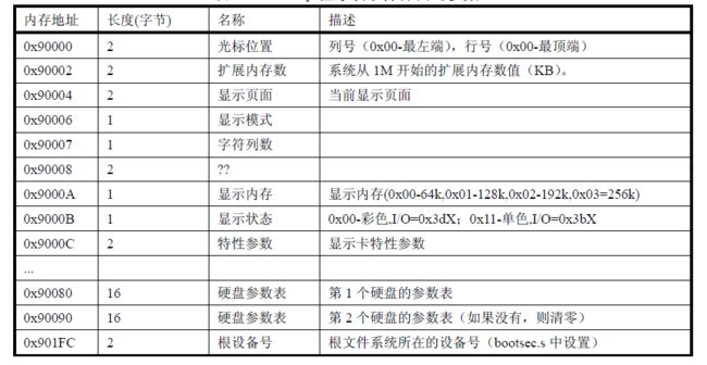
保存光标位置信息在0x90000处,控制台初始化时会来取
# ok, the read went well so we get current cursor position and save it for
# posterity.

    mov    $INITSEG, %ax    # this is done in bootsect already, but...
    mov    %ax, %ds
    mov    $0x03, %ah    # read cursor pos
    xor    %bh, %bh
    int    $0x10        # save it in known place, con_init fetches
    mov    %dx, %ds:0    # it from 0x90000.
获取内存大小
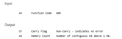
# Get memory size (extended mem, kB)

    mov    $0x88, %ah
    int    $0x15
    mov    %ax, %ds:2
获取显示卡显示模式
中断0x10 ,功能号ah=0x0f
返回:ah=字符列数 al=显示模式 bh=当前显示页
# Get video-card data:

    mov    $0x0f, %ah
    int    $0x10
    mov    %bx, %ds:4    # bh = display page
    mov    %ax, %ds:6    # al = video mode, ah = window width
EGA、VGA检查显示模式
中断0x10 ,功能号=0x12,bl=0x10
返回:bh=显示状态(0x00彩色模式,IO=0x3dX)(0x01单色模式,IO=0x3bX)
bl=安装的显存(0x00 64k; 0x01 128k; 0x02 192k; 0x03 256k)
cx = 显示卡特性参数
# check for EGA/VGA and some config parameters

    mov    $0x12, %ah
    mov    $0x10, %bl
    int    $0x10
    mov    %ax, %ds:8  # ds=0x90000
    mov    %bx, %ds:10
    mov    %cx, %ds:12
取第一个硬盘的信息,第一个硬盘参数表首地址竟然是中断向量0x41,第二个硬盘参数表紧接第一个表的后面,中断向量0x46的向量值也指向第2个硬盘的参数表首地址。表的长度为16字节0x10
LDS——偏移地址及其数据段段地址传送指令 LDS r16,mem
从mem存储单元开始的4个连续存储单元中取出某变量的地址指针(共4个字节),将其前两个字节(即变量的偏移地址)传送到r16,后两个字节(即变量的段地址)传送到DS段寄存器中
# Get hd0 data

    mov    $0x0000, %ax
    mov    %ax, %ds
    lds    %ds:4*0x41, %si # 104h
    mov    $INITSEG, %ax
    mov    %ax, %es
    mov    $0x0080, %di
    mov    $0x10, %cx
    rep
    movsb

# Get hd1 data

    mov    $0x0000, %ax
    mov    %ax, %ds
    lds    %ds:4*0x46, %si # 118h
    mov    $INITSEG, %ax
    mov    %ax, %es
    mov    $0x0090, %di
    mov    $0x10, %cx
    rep
    movsb
检查硬盘是否存在第二个硬盘
功能15H
功能描述:读取磁盘类型
入口参数:AH=15H
DL=驱动器,00H~7FH:软盘;80H~0FFH:硬盘
出口参数:CF=1——操作失败,AH=状态代码,参见功能号01H中的说明, 否则,AH=00H — 未安装驱动器
=01H — 无改变线支持的软盘驱动器
=02H — 带有改变线支持的软盘驱动器
=03H — 硬盘,CX:DX=512字节的扇区数
# Check that there IS a hd1 :-)

    mov    $0x01500, %ax
    mov    $0x81, %dl # 0x81是第二个硬盘,0x80是第一个硬盘
    int    $0x13
    jc    no_disk1
    cmp    $3, %ah
    je    is_disk1
no_disk1:
    mov    $INITSEG, %ax
    mov    %ax, %es
    mov    $0x0090, %di
    mov    $0x10, %cx
    mov    $0x00, %ax
    rep
    stosb
is_disk1:
# now we want to move to protected mode ...

    cli            # no interrupts allowed ! 关闭中断,后面会覆盖BIOS中断
将system模块从0x10000-0x8ffff到0x00000到0x7ffff,system模块最大长度不会超过0x80000(512k),末端不会超过内存地址0x90000
# first we move the system to it's rightful place

    mov    $0x0000, %ax
    cld            # 'direction'=0, movs moves forward
do_move:
    mov    %ax, %es    # destination segment
    add    $0x1000, %ax
    cmp    $0x9000, %ax
    jz    end_move
    mov    %ax, %ds    # source segment
    sub    %di, %di
    sub    %si, %si
    mov     $0x8000, %cx
    rep
    movsw
    jmp    do_move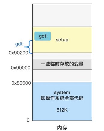
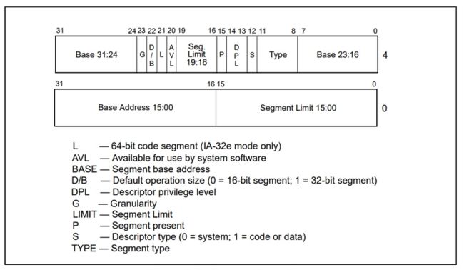
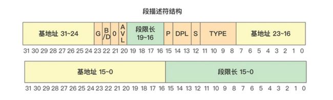
lidt指令用于加载中断描述符(idt)寄存器,它的操作数是6个字节,0-1字节是描述符表长度值,2-5字节是描述符表的32位线性基地址
lgdt指令用于加载全局描述符表(gdt)寄存器,其操作数格式与lidt指令相同。全局描述符表中的每个描述符项(8字节)描述了保护模式下数据和代码段的信息。其中包括段的最大长度限制16位,段的线性基址32位,段的特权级,段是否存在内存,读写许可以及其它一些保护模式运行的标志。

# 全局描述符表开始处,描述符表由多个8字节长描述符项组成
# 三个描述符,第一项无用
gdt:

#第0个描述符,不用
    .word    0,0,0,0        # dummy

#第1个描述符,系统代码段描述符
    .word    0x07FF        # 8Mb - limit=2047 (2048*4096=8Mb)
    .word    0x0000        # base address=0
    .word    0x9A00        # code read/exec
    .word    0x00C0        # granularity=4096, 386

#第2个描述符,系统数据段描述符
    .word    0x07FF        # 8Mb - limit=2047 (2048*4096=8Mb)
    .word    0x0000        # base address=0
    .word    0x9200        # data read/write
    .word    0x00C0        # granularity=4096, 386
end_move:
mov $SETUPSEG, %ax # right, forgot this at first. didn't work :-)
mov %ax, %ds
lidt idt_48 # load idt with 0,0
lgdt gdt_48 # load gdt with whatever appropriate
# This routine checks that the keyboard command queue is empty
# No timeout is used - if this hangs there is something wrong with
# the machine, and we probably couldn't proceed anyway.
#子程序检查键盘命令队列是否为空,这里不使用超时方法,只有当输入缓冲器为空时(状态寄存器2=0)才可以对其进行写命令
empty_8042:
.word 0x00eb,0x00eb #两个跳转指令的机器码,相当于延时空操作
in $0x64, %al # 8042 status port #读AT键盘控制器状态寄存器
test $2, %al # is input buffer full? #测试位2,输入缓冲器满?
jnz empty_8042 # yes - loop #yes loop
ret
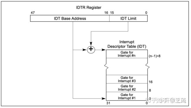
#* IDTR(48bit)
#中断描述符表寄存器,指向了中断描述符表IDT,这个表的每一项都是一个中断处理描述符,
#当CPU执行过程中发生了硬中断、异常、软中断时,将自动从这个表中定位对应的表项,里面记录了发生中断、异常时该去哪里执行处理函数。
idt_48:
.word 0 # idt limit=0
.word 0,0 # idt base=0L
#* GDTR(48bit)
#全局描述符表寄存器,CPU现在使用的是段+分页结合的内存管理方式,那系统总共有那些分段呢?
#这就存储在一个叫全局描述符表(GDT)的表格中,并用gdtr寄存器指向这个表。这个表中的每一项都描述了一个内存段的信息。
gdt_48:
.word 0x800 # gdt limit=2048, 256 GDT entries
.word 512+gdt, 0x9 # gdt base = 0X9xxxx,
# 512+gdt is the real gdt after setup is moved to 0x9020 * 0x10#可以看到这个标签位置处表示一个 48 位的数据,其中高 32 位存储着的正是全局描述符表 gdt 的内存地址 0x90200 + gdt。
#gdt 是个标签,表示在本文件 setup.s 内的偏移量,不过准确说是 setup.s 被编译成 setup 二进制文件后,gdt 所在的内存偏移量。

控制A20总线的端口被称为A20-Gate。使用in/out指令控制,即可控制A20总线是否打开。A20 Gate是0x92端口的第二个bit。先获得0x92端口的值并存放在al寄存器中,然后通过or将该寄存器的第二个bit设置为1。然后再将al的值写入0x92端口即可。
打开A20地址线,突破地址信号线20位的宽度,变成32位可用。
# that was painless, now we enable A20

    inb     $0x92, %al    # open A20 line(Fast Gate A20).
    orb     $0b00000010, %al
    outb    %al, $0x92
重新对8259中断控制器进行编程
# well, that went ok, I hope. Now we have to reprogram the interrupts :-(
# we put them right after the intel-reserved hardware interrupts, at
# int 0x20-0x2F. There they won't mess up anything. Sadly IBM really
# messed this up with the original PC, and they haven't been able to
# rectify it afterwards. Thus the bios puts interrupts at 0x08-0x0f,
# which is used for the internal hardware interrupts as well. We just
# have to reprogram the 8259's, and it isn't fun.

    mov    $0x11, %al        # initialization sequence(ICW1)
                    # ICW4 needed(1),CASCADE mode,Level-triggered
    out    %al, $0x20        # send it to 8259A-1
    .word    0x00eb,0x00eb        # jmp $+2, jmp $+2
    out    %al, $0xA0        # and to 8259A-2
    .word    0x00eb,0x00eb
    mov    $0x20, %al        # start of hardware int's (0x20)(ICW2)
    out    %al, $0x21        # from 0x20-0x27
    .word    0x00eb,0x00eb
    mov    $0x28, %al        # start of hardware int's 2 (0x28)
    out    %al, $0xA1        # from 0x28-0x2F
    .word    0x00eb,0x00eb        #               IR 7654 3210
    mov    $0x04, %al        # 8259-1 is master(0000 0100) --\
    out    %al, $0x21        #                |
    .word    0x00eb,0x00eb        #             INT    /
    mov    $0x02, %al        # 8259-2 is slave(       010 --> 2)
    out    %al, $0xA1
    .word    0x00eb,0x00eb
    mov    $0x01, %al        # 8086 mode for both
    out    %al, $0x21
    .word    0x00eb,0x00eb
    out    %al, $0xA1
    .word    0x00eb,0x00eb
    mov    $0xFF, %al        # mask off all interrupts for now
    out    %al, $0x21
    .word    0x00eb,0x00eb
    out    %al, $0xA1
进入32位保护模式运行
# well, that certainly wasn't fun :-(. Hopefully it works, and we don't
# need no steenking BIOS anyway (except for the initial loading :-).
# The BIOS-routine wants lots of unnecessary data, and it's less
# "interesting" anyway. This is how REAL programmers do it.
#
# Well, now's the time to actually move into protected mode. To make
# things as simple as possible, we do no register set-up or anything,
# we let the gnu-compiled 32-bit programs do that. We just jump to
# absolute address 0x00000, in 32-bit protected mode.
mov %cr0, %eax # get machine status(cr0|MSW)
bts $0, %eax # turn on the PE-bit
mov %eax, %cr0 # protection enabled
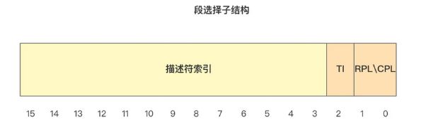
# segment-descriptor (INDEX:TI:RPL)
.equ sel_cs0, 0x0008 # select for code segment 0 ( 001:0 :00)
ljmp $sel_cs0, $0 # jmp offset 0 of code segment 0 in gdt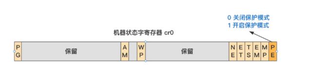
ljmp cs=8 ip=0,此时处于保护模式,0000 0000 0000 1000,所以描述符索引是1,就是去全局描述符表GDT中找索引1的描述符
第0项为空,第1项是代码段描述符,第2项是数据段描述符