基于Ti Omap3x 分析v4l2架构
1 概述
本文将基于Ti Omap3x这个典型的实例来分析v4l2在具体media场景中的应用。通过分析app层的行为以及driver层的实现来对整个多媒体框架有一个大概的认识。内容主要包括主要包括v4l2-core、meida framework。
前几章的内容借鉴了这篇文章:
【原创】Linux v4l2框架分析 - LoyenWang - 博客园
2 . 基本原理分析
2.1 v4l2-core
2.1.1 应用视角
先从应用的角度来看如何使用v4l2吧:
上面的框图是对v4l2的一个典型应用。左边的框图是一个video 采集的基本流程,不涉及对子设备的操作,实际使用过程中融合了media框架以后,应用场景会更复杂。在Ti Omap3x 的实现中,有的v4l2_device只有一个,用来虚拟整个多媒体设备,但会有多个video device,有的video device会关联v4l2 sub device设备,这些sub device 通过注册video device 向上层暴露文件节点,以使应用层通过这些文件节点可以直接操作这些sub device, 而有些video device 不关联 sub device,则他可能直接用于video 的采集。
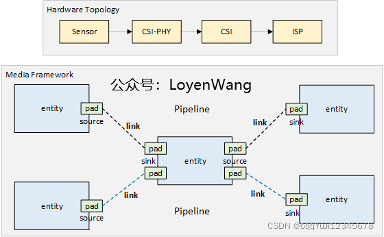
可以先看一下较常见的硬件拓扑结构:
- 通常一个camera的模组如图所示,通常包括Lens、Sensor、CSI接口等,其中CSI接口用于视频数据的传输;
- SoC的Mipi接口对接Camera,并通过I2C/SPI控制camera模组;
- Camera模组中也可以包含ISP模块,用于对图像进行处理,有的SoC中也集成了ISP的IP,接收camera的raw数据后,进行图像处理。
2.1.2 数据结构
如果以上图的硬件为例,对摄像头的硬件该怎么来抽象呢?没错,就是以v4l2_device和v4l2_subdev来进行抽象,以v4l2_device来代表整个输入设备,以v4l2_subdev来代表子模块,比如CSI、Sensor等;
v4l2_device:对视频设备的整体进行抽象,可以看成是一个纽带,将各个子设备联系在一起,通常它会嵌入在其他结构体中以提供v4l2框架的功能,比如strcut isp_device;v4l2_subdev:对子设备进行抽象,该结构体中包含的struct v4l2_subdev_ops是一个完备的操作函数集,用于对接各种不同的子设备,比如video、audio、sensor等,同时还有一个核心的函数集struct v4l2_subdev_core_ops,提供更通用的功能。子设备驱动根据设备特点实现该函数集中的某些函数即可;video_device:用于向系统注册字符设备节点,以便用户空间可以进行交互,包括各类设置以及数据buffer的获取等,在该结构体中也能看到struct v4l2_ioctl_ops和struct vb2_queue结构体字段,这些与上文中的应用层代码编写息息相关,如果子设备需要和应用层交互,则需要关联video_device结构,通过该结构应用层可以直接控制子设备;- 如果子设备不需要与应用层交互,
struct v4l2_subdev中内嵌的video_device也可以不向系统注册字符设备; video_device结构体,可以内嵌在其他结构体中,以便提供用户层交互的功能,比如struct isp_video;
2.1.3 流程分析
来进一步看一下内部的注册,及调用流程吧:
- 在驱动实现中,驱动结构体中内嵌
struct video_device,同时实现struct v4l2_file_operations结构体中的函数,最终通过video_register_device向提供注册; v4l2_register_device函数通过cdev_add向系统注册字符设备,并指定了file_operations,用户空间调用open/read/write/ioctl等接口,便可回调到驱动实现中;v4l2_register_device函数中,通过device_register向系统注册设备,会在/sys文件系统下创建节点;
完成注册后,用户空间便可通过文件描述符来进行访问,从应用层看,大部分都是通过ioctl接口来完成,流程如下:
- 用户层的
ioctl回调到__video_do_ioctl中,该函数会对系统提供的struct v4l2_ioctl_info v4l2_ioctls[]表进行查询,找到对应的项后进行调用; - 驱动做的工作就是填空题,实现对应的回调,在合适的时候被调用;
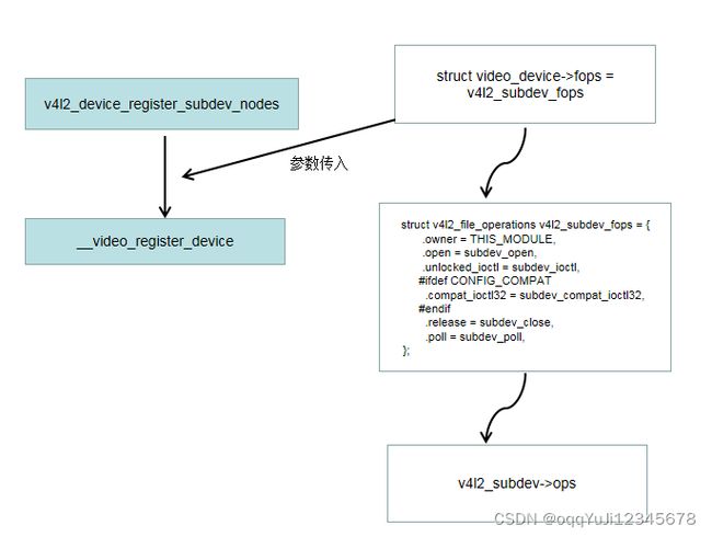
当sub device设置了V4L2_SUBDEV_FL_HAS_DEVNODE flag以后,调用v4l2_device_register_subdev_nodes函数也会注册video device节点,并且该video device的fops会被设置成v4l2_subdev_fops函数,所有对video device节点的操作会被转换成对sub device的操作:
2.2 media framework
2.2.1 问题引入
本节以omap3isp为例,先看一下它的硬件构成:
- CSI:camera接口,接收图像数据,RGB/YUV/JPEG等;
- CCDC:视频处理前端,CCDC为图像传感器和数字视频源提供接口,并处理图像数据;
- Preview/Resizer:视频处理后端,Preview提供预览功能,可针对不同类型的传感器进行定制,Resizer提供将输入图像数据按所需的显示或视频编码分辨率调整大小的方法;
- H3A/HIST:静态统计模块,H3A支持AF、AWB、AE的回路控制,HIST根据输入数据,提供各种3A算法所需的统计数据;
上述硬件模块,可以对应到驱动结构体struct isp_device中的各个字段。
omap3isp的硬件模块,支持多种数据流通路,它并不是唯一的,以RGB为例,如下图:
- Raw RGB数据进入ISP模块后,可以在运行过程中,根据实际的需求进行通路设置;
- 所以,重点是:它需要动态设置路径!
那么,软件该如何满足这种需求呢?
2.2.2 框架
pipeline框架的引入可以解决这个问题
- 模块之间相互独立,通过
struct media_entity来进行抽象,通常会将struct media_entity嵌入到其他结构中,比如video device或者sub device以支持media framework功能,这样就可以把media_entity和具体的设备相关联 - 模块包含
struct media_pad,pad可以认为是端口,与其他模块进行联系的媒介,针对特定模块来说它是确定的; - pad通过
struct media_link来建立连接,指定source和sink,即可将通路建立起来; - 各个模块之间最终建立一条数据流,便是一条pipeline了,同一条pipeline中的模块,可以根据前一个模块查找到下一个模块,因此也可以很方便进行遍历,并做进一步的设置操作;
因此,只需要将struct media_entity嵌入到特定子模块中,最终便可以将子模块串联起来,构成数据流。所以,omap3isp的驱动中,数据流就如下图所示:
video devnode代表video device,也就是前文中提到的导出到用户空间的节点,用于与用户进行控制及数据交互;- 每个模块分别有source pad和sink pad,从连接图就可以看出,数据通路灵活多变;
- 至于数据通路选择问题,可以在驱动初始化的时候进行链接创建,比如
isp_create_links;
还是看一下数据结构吧:
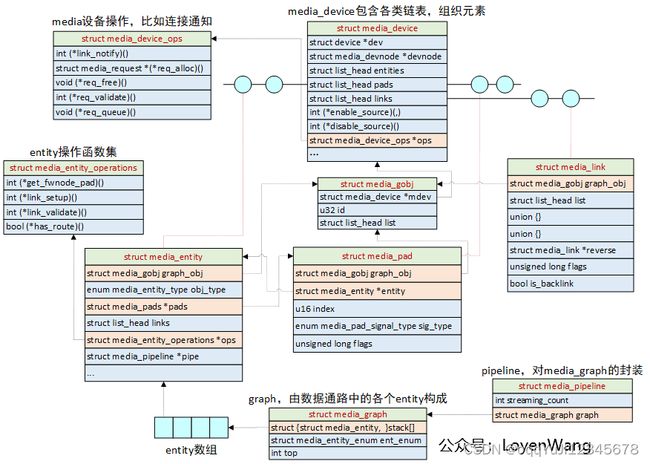
media_device:与v4l2_device类似,也是负责将各个子模块集中进行管理,同时在注册的时候,会向系统注册设备节点,方便用户层进行操作;media_entity、media_pad、media_link等结构体的功能在上文中描述过,注意,这几个结构体会添加到media_device的链表中,同时它们结构体的开始字段都需是struct media_gobj,该结构中的mdev将会指向它所属的media_device。这种设计方便结构之间的查找;media_entity中包含多个media_pad,同时media_pad又会指向它所属的media_entity;media_graph和media_pipeline是media_entity的集合,直观来理解,就是由一些模块构成的一条数据通路,由一个统一的数据结构来组织管理;
3 . 代码分析
上面分析完了框架,下面就从代码实现的角度看一下。 Ti 的omap3x的driver在新版的kernel里都有实现,代码在drivers/media/platform/omap3isp/ 目录下。 app层的使用实例可以在该链接下载到:
https://git.ideasonboard.org/
3.1 driver 代码分析
omap3x driver 加载的函数是isp_probe,现在着重分析里面的几个关键函数:
static int isp_probe(struct platform_device *pdev)
{

...........
ret = isp_parse_of_endpoints(isp); .......(1)
...........
ret = isp_initialize_modules(isp); ........(2)
if (ret < 0)
	goto error_iommu;

ret = isp_register_entities(isp); ..........(3)
if (ret < 0)
	goto error_modules;

ret = isp_create_links(isp);  ..........(4)
if (ret < 0)
	goto error_register_entities;

isp->notifier.ops = &isp_subdev_notifier_ops;

ret = v4l2_async_notifier_register(&isp->v4l2_dev, &isp->notifier); ........(5)

..................

}
(1)看一下isp_parse_of_endpoints,这个函数是解析device tree,获取dts中描述的视频设备的port的endpoint里的remote endpoint节点,并且通过该节点找到连接的remote 设备。可以看一下这类dts的设备树大概如何写:
i2c0: i2c@fff20000 {
                ...


                imx074: camera@1a {
                        compatible = "sony,imx074";
                        reg = <0x1a>;
                        vddio-supply = <®ulator1>;
                        vddcore-supply = <®ulator2>;

                        clock-frequency = <30000000>;   /* Shared clock with ov772x_1 */
                        clocks = <&mclk 0>;
                        clock-names = "sysclk";         /* Assuming this is the
                                                           name in the datasheet */
                        port {
                                imx074_1: endpoint {
                                        clock-lanes = <0>;
                                        data-lanes = <1 2>;
                                        remote-endpoint = <&csi2_1>;
                                };
                        };
                };

    };

csi2: csi2@ffc90000 {
                compatible = "renesas,sh-mobile-csi2";
                reg = <0xffc90000 0x1000>;
                interrupts = <0x17a0>;
                #address-cells = <1>;
                #size-cells = <0>;

                port@1 {
                        compatible = "renesas,csi2c";   /* One of CSI2I and CSI2C. */
                        reg = <1>;                      /* CSI-2 PHY #1 of 2: PHY_S,
                                                           PHY_M has port address 0,
                                                           is unused. */
                        csi2_1: endpoint {
                                clock-lanes = <0>;
                                data-lanes = <2 1>;
                                remote-endpoint = <&imx074_1>;
                        };
                };

        };
所以如果该设备是csi2,则解析其接口的时候,其port的endpoint1的remote endpoint就是imx074_1,其parent 节点就是imx074,这样就找到了sensor设备,把该设备注册到异步通知链中,如果sensor驱动加载了就会匹配起来,向系统注册sub device设备,主要视频设备和sensor的通路就连接起来了。
可以看一下部分代码:
static int isp_parse_of_endpoints(struct isp_device *isp)
{
	struct fwnode_handle *ep;
	struct isp_async_subdev *isd = NULL;
	struct isp_bus_cfg *buscfg;
	unsigned int i;

	ep = fwnode_graph_get_endpoint_by_id(
		dev_fwnode(isp->dev), ISP_OF_PHY_PARALLEL, 0,
		FWNODE_GRAPH_ENDPOINT_NEXT);

	if (ep) {
		struct v4l2_fwnode_endpoint vep = {
			.bus_type = V4L2_MBUS_PARALLEL
		};
		int ret;

		dev_dbg(isp->dev, "parsing parallel interface\n");

		ret = v4l2_fwnode_endpoint_parse(ep, &vep);

		if (!ret) {
			ret = isp_alloc_isd(&isd, &buscfg);
			if (ret)
				return ret;
		}

		if (!ret) {
			isp_parse_of_parallel_endpoint(isp->dev, &vep, buscfg);
			ret = v4l2_async_notifier_add_fwnode_remote_subdev(
				&isp->notifier, ep, &isd->asd);
		}
这边先尝试解析并行接口,找到并行接口的endpoint以后,就调用v4l2_async_notifier_add_fwnode_remote_subdev尝试寻找remote endpoint的parent节点,如果找到就放入v4l2_async_subdev 结构中,并且注册到异步通知链中等待后面匹配
(2)isp_initialize_modules 中对csi2,ccp2,ccdc,preview,resizer,hist,h3a,h3a_af等子设备进行初始化,以ccdc的初始化为例,看一下具体做了哪些工作:
omap3isp_ccdc_init
-------->ccdc_init_entities
static int ccdc_init_entities(struct isp_ccdc_device *ccdc)
{
	struct v4l2_subdev *sd = &ccdc->subdev;
	struct media_pad *pads = ccdc->pads;
	struct media_entity *me = &sd->entity;
	int ret;

	ccdc->input = CCDC_INPUT_NONE;

	v4l2_subdev_init(sd, &ccdc_v4l2_ops);
	sd->internal_ops = &ccdc_v4l2_internal_ops;
	strscpy(sd->name, "OMAP3 ISP CCDC", sizeof(sd->name));
	sd->grp_id = 1 << 16;	/* group ID for isp subdevs */
	v4l2_set_subdevdata(sd, ccdc);
	sd->flags |= V4L2_SUBDEV_FL_HAS_EVENTS | V4L2_SUBDEV_FL_HAS_DEVNODE;

	pads[CCDC_PAD_SINK].flags = MEDIA_PAD_FL_SINK
				    | MEDIA_PAD_FL_MUST_CONNECT;
	pads[CCDC_PAD_SOURCE_VP].flags = MEDIA_PAD_FL_SOURCE;
	pads[CCDC_PAD_SOURCE_OF].flags = MEDIA_PAD_FL_SOURCE;

	me->ops = &ccdc_media_ops;
	ret = media_entity_pads_init(me, CCDC_PADS_NUM, pads);
	if (ret < 0)
		return ret;

	ccdc_init_formats(sd, NULL);

	ccdc->video_out.type = V4L2_BUF_TYPE_VIDEO_CAPTURE;
	ccdc->video_out.ops = &ccdc_video_ops;
	ccdc->video_out.isp = to_isp_device(ccdc);
	ccdc->video_out.capture_mem = PAGE_ALIGN(4096 * 4096) * 3;
	ccdc->video_out.bpl_alignment = 32;

	ret = omap3isp_video_init(&ccdc->video_out, "CCDC");
	if (ret < 0)
		goto error;

	return 0;

error:
	media_entity_cleanup(me);
	return ret;
}
该函数初始化了sub device结构,并设置了其操作函数集,并且初始化该sub device包含的media entity,设置其sink和source pad,设置了V4L2_SUBDEV_FL_HAS_DEVNODEflag,该sub device 后面会向应用层暴露video device接口,从而应用层可以直接操作该sub device,media entity的惭怍函数集被设置成ccdc_media_ops,这样后面连接上其他的media entity 会调用里面的ccdc_link_setup回调,接着调用omap3isp_video_init 对video_out 进行初始化,他是对video_device的进一步分装,该节点主要用于视频向memory的输出,不关联sub device。
总结一下,上面初始化了sub device 和video_out,其中sub device 和video_out的video_device中都包含media entity,所以在media 框架中他们都属于单独的实体,在满足条件的情况下可以和其他的实体建立连接,并且在v4l2框架内ccdc抽象成sub device,操作sub device即可设置ccdc的相关功能,而video_out则作为一个video节点,可以进行video buffer的管理。其他的模块初始化也是类似的。
(3)isp_register_entities 初始化media device设备,然后向其注册前面初始化的sub device和video_device的entity实体。media device在media框架里面的作用跟 v4l2 device在v4l2框架里的作用差不多。他们都是对整个多媒体设备的抽象。media device 用来管理系统中所有的entity,而v4l2 device用来管理所有的sub device.
struct media_device {
	/* dev->driver_data points to this struct. */
	struct device *dev;
	struct media_devnode *devnode;

	char model[32];
	char driver_name[32];
	char serial[40];
	char bus_info[32];
	u32 hw_revision;

	u64 topology_version;

	u32 id;
	struct ida entity_internal_idx;
	int entity_internal_idx_max;

	struct list_head entities;
	struct list_head interfaces;
	struct list_head pads;
	struct list_head links;

};
可以看到media device里面有pads,entity 和link的链表存在,通过结构就能知道系统中所有的entity以及他们之间的连接关系。
static int isp_register_entities(struct isp_device *isp)
{
	int ret;

	isp->media_dev.dev = isp->dev;
	strscpy(isp->media_dev.model, "TI OMAP3 ISP",
		sizeof(isp->media_dev.model));
	isp->media_dev.hw_revision = isp->revision;
	isp->media_dev.ops = &isp_media_ops;
	media_device_init(&isp->media_dev);

	isp->v4l2_dev.mdev = &isp->media_dev;
	ret = v4l2_device_register(isp->dev, &isp->v4l2_dev);
	if (ret < 0) {
		dev_err(isp->dev, "%s: V4L2 device registration failed (%d)\n",
			__func__, ret);
		goto done;
	}
。。。。。。。。。。。。

	ret = omap3isp_ccdc_register_entities(&isp->isp_ccdc, &isp->v4l2_dev);
。。。。。。。。。。。。
在omap3isp_ccdc_register_entities中调用v4l2_device_register_subdev 和omap3isp_video_register,把sub device和video_out节点中的media entity加入到media device的链表中,并且video_out中的video device创建设备节点,方便用户层控制。
(4)isp_create_links中在不同的entity中建立link,通过这些link,就把不同的entity串联起来了:
static int isp_create_links(struct isp_device *isp)
{
	int ret;

	/* Create links between entities and video nodes. */
	ret = media_create_pad_link(
			&isp->isp_csi2a.subdev.entity, CSI2_PAD_SOURCE,
			&isp->isp_csi2a.video_out.video.entity, 0, 0);
	if (ret < 0)
		return ret;

	ret = media_create_pad_link(
			&isp->isp_ccp2.video_in.video.entity, 0,
			&isp->isp_ccp2.subdev.entity, CCP2_PAD_SINK, 0);
	if (ret < 0)
		return ret;

	ret = media_create_pad_link(
			&isp->isp_ccdc.subdev.entity, CCDC_PAD_SOURCE_OF,
			&isp->isp_ccdc.video_out.video.entity, 0, 0);
	if (ret < 0)
		return ret;

	ret = media_create_pad_link(
			&isp->isp_prev.video_in.video.entity, 0,
			&isp->isp_prev.subdev.entity, PREV_PAD_SINK, 0);
	if (ret < 0)
		return ret;

	ret = media_create_pad_link(
			&isp->isp_prev.subdev.entity, PREV_PAD_SOURCE,
			&isp->isp_prev.video_out.video.entity, 0, 0);
	if (ret < 0)
		return ret;

	ret = media_create_pad_link(
			&isp->isp_res.video_in.video.entity, 0,
			&isp->isp_res.subdev.entity, RESZ_PAD_SINK, 0);
	if (ret < 0)
		return ret;

	ret = media_create_pad_link(
			&isp->isp_res.subdev.entity, RESZ_PAD_SOURCE,
			&isp->isp_res.video_out.video.entity, 0, 0);

	if (ret < 0)
		return ret;

	/* Create links between entities. */
	ret = media_create_pad_link(
			&isp->isp_csi2a.subdev.entity, CSI2_PAD_SOURCE,
			&isp->isp_ccdc.subdev.entity, CCDC_PAD_SINK, 0);
	if (ret < 0)
		return ret;

	ret = media_create_pad_link(
			&isp->isp_ccp2.subdev.entity, CCP2_PAD_SOURCE,
			&isp->isp_ccdc.subdev.entity, CCDC_PAD_SINK, 0);
	if (ret < 0)
		return ret;

	ret = media_create_pad_link(
			&isp->isp_ccdc.subdev.entity, CCDC_PAD_SOURCE_VP,
			&isp->isp_prev.subdev.entity, PREV_PAD_SINK, 0);
	if (ret < 0)
		return ret;

	ret = media_create_pad_link(
			&isp->isp_ccdc.subdev.entity, CCDC_PAD_SOURCE_OF,
			&isp->isp_res.subdev.entity, RESZ_PAD_SINK, 0);
	if (ret < 0)
		return ret;

	ret = media_create_pad_link(
			&isp->isp_prev.subdev.entity, PREV_PAD_SOURCE,
			&isp->isp_res.subdev.entity, RESZ_PAD_SINK, 0);
	if (ret < 0)
		return ret;

	ret = media_create_pad_link(
			&isp->isp_ccdc.subdev.entity, CCDC_PAD_SOURCE_VP,
			&isp->isp_aewb.subdev.entity, 0,
			MEDIA_LNK_FL_ENABLED | MEDIA_LNK_FL_IMMUTABLE);
	if (ret < 0)
		return ret;

	ret = media_create_pad_link(
			&isp->isp_ccdc.subdev.entity, CCDC_PAD_SOURCE_VP,
			&isp->isp_af.subdev.entity, 0,
			MEDIA_LNK_FL_ENABLED | MEDIA_LNK_FL_IMMUTABLE);
	if (ret < 0)
		return ret;

	ret = media_create_pad_link(
			&isp->isp_ccdc.subdev.entity, CCDC_PAD_SOURCE_VP,
			&isp->isp_hist.subdev.entity, 0,
			MEDIA_LNK_FL_ENABLED | MEDIA_LNK_FL_IMMUTABLE);
	if (ret < 0)
		return ret;

	return 0;
}
应用层可以通过media device设备的操作集来操作这些entity和link。
(5)v4l2_async_notifier_register 异步通知链上匹配其他的driver注册的sub device:
static int __v4l2_async_notifier_register(struct v4l2_async_notifier *notifier)
{
	struct v4l2_async_subdev *asd;
	int ret, i = 0;

	INIT_LIST_HEAD(¬ifier->waiting);
	INIT_LIST_HEAD(¬ifier->done);

	mutex_lock(&list_lock);

	list_for_each_entry(asd, ¬ifier->asd_list, asd_list) {
		ret = v4l2_async_notifier_asd_valid(notifier, asd, i++);
		if (ret)
			goto err_unlock;
//把driver 一开始在dts 里面探测到的remote endponit的节点放到通知链的waiting中等待匹配
		list_add_tail(&asd->list, ¬ifier->waiting);
	}

//尝试从subdev_list list中查找sub device,如果找到匹配的,比如和某个sensor driver
匹配,则把该sub device注册到v4l2 device中,并且把其media entity 放入media device中。
	ret = v4l2_async_notifier_try_all_subdevs(notifier);
	if (ret < 0)
		goto err_unbind;

调用notify通知链的complete函数。
	ret = v4l2_async_notifier_try_complete(notifier);
	if (ret < 0)
		goto err_unbind;

	/* Keep also completed notifiers on the list */
	list_add(¬ifier->list, ¬ifier_list);

	mutex_unlock(&list_lock);

	return 0;

err_unbind:
	/*
	 * On failure, unbind all sub-devices registered through this notifier.
	 */
	v4l2_async_notifier_unbind_all_subdevs(notifier);

err_unlock:
	mutex_unlock(&list_lock);

	return ret;
}
notify的complete通知链函数为isp_subdev_notifier_complete:
static int isp_subdev_notifier_complete(struct v4l2_async_notifier *async)
{
	struct isp_device *isp = container_of(async, struct isp_device,
					      notifier);
	struct v4l2_device *v4l2_dev = &isp->v4l2_dev;
	struct v4l2_subdev *sd;
	int ret;

	ret = media_entity_enum_init(&isp->crashed, &isp->media_dev);
	if (ret)
		return ret;

	list_for_each_entry(sd, &v4l2_dev->subdevs, list) {
		if (sd->notifier != &isp->notifier)
			continue;

		ret = isp_link_entity(isp, &sd->entity,
				      v4l2_subdev_to_bus_cfg(sd)->interface);
		if (ret < 0)
			return ret;
	}
//搜索v4l2 device下面挂载的所有的sub device,为设置了V4L2_SUBDEV_FL_HAS_DEVNODE flag
的sub device分配 video device节点,并创建文件节点,暴露给应用层调用
	ret = v4l2_device_register_subdev_nodes(&isp->v4l2_dev);
	if (ret < 0)
		return ret;

//为media device创建设备节点,方便用户层管理media entity 节点。
	return media_device_register(&isp->media_dev);
}
至此driver的初始化基本完成。
总结一下,驱动抽象了csi2,ccp2,ccdc,preview等结构,例如ccdc用isp_ccdc_device结构来描述,该结构内部包含有sub device和video_out 结构,通过sub device结构可以操作ccdc,而通过video_out 可以操作video的output buffer,这两个结构内部的media entity可以通过link连接起来,形成pipline。
3.2 app 代码分析
Ti 的omap3isp 工程中给出了一些简单得我示例代码。下面简单分析一下omap3-isp-dsp 这个程序。
isp.mdev = media_open(MEDIA_DEVICE, 0);首先会调用media open这个函数,这面会打开driver 里面注册的media device的节点,通过该节点,可以直接获取到系统的media entity的具体情况以及相互之间的联系:
struct media_device *media_open(const char *name, int verbose)
{
	struct media_device *media;
	int ret;

	media = malloc(sizeof(*media));
	if (media == NULL) {
		printf("%s: unable to allocate memory\n", __func__);
		return NULL;
	}
	memset(media, 0, sizeof(*media));

	if (verbose)
		printf("Opening media device %s\n", name);
	media->fd = open(name, O_RDWR);
	if (media->fd < 0) {
		media_close(media);
		printf("%s: Can't open media device %s\n", __func__, name);
		return NULL;
	}

	ret = ioctl(media->fd, MEDIA_IOC_DEVICE_INFO, &media->info);
	if (ret < 0) {
		printf("%s: Unable to retrieve media device information for "
		       "device %s (%s)\n", __func__, name, strerror(errno));
		media_close(media);
		return NULL;
	}

	if (verbose)
		printf("Enumerating entities\n");

	ret = media_enum_entities(media);
	if (ret < 0) {
		printf("%s: Unable to enumerate entities for device %s (%s)\n",
			__func__, name, strerror(-ret));
		media_close(media);
		return NULL;
	}

	if (verbose) {
		printf("Found %u entities\n", media->entities_count);
		printf("Enumerating pads and links\n");
	}

	ret = media_enum_links(media);
	if (ret < 0) {
		printf("%s: Unable to enumerate pads and linksfor device %s\n",
			__func__, name);
		media_close(media);
		return NULL;
	}

	return media;
}
之前driver中已经初始化了media entity和link,所以这里调用media device的ioctl可以获取到driver中的entity和link的具体状态。所有的media entity以及link,其拓扑打印出来大概入下所示:
Openingmedia device /dev/media0
Enumeratingentities
Found16 entities
Enumeratingpads and links
Devicetopology
-entity 1: OMAP3 ISP CCP2 (2 pads, 2 links)
            type V4L2 subdev subtype Unknown
            device node name /dev/v4l-subdev0
        pad0: Input [SGRBG10 4096x4096]
                <- 'OMAP3 ISP CCP2input':pad0 []
        pad1: Output [SGRBG10 4096x4096]
                -> 'OMAP3 ISP CCDC':pad0 []

-entity 2: OMAP3 ISP CCP2 input (1 pad, 1 link)
            type Node subtype V4L
            device node name /dev/video0
        pad0: Output
                -> 'OMAP3 ISP CCP2':pad0 []

-entity 3: OMAP3 ISP CSI2a (2 pads, 2 links)
            type V4L2 subdev subtype Unknown
            device node name /dev/v4l-subdev1
        pad0: Input [SGRBG10 4096x4096]
        pad1: Output [SGRBG10 4096x4096]
                -> 'OMAP3 ISP CSI2aoutput':pad0 []
                -> 'OMAP3 ISP CCDC':pad0 []

-entity 4: OMAP3 ISP CSI2a output (1 pad, 1 link)
            type Node subtype V4L
            device node name /dev/video1
        pad0: Input
                <- 'OMAP3 ISP CSI2a':pad1 []

-entity 5: OMAP3 ISP CCDC (3 pads, 9 links)
            type V4L2 subdev subtype Unknown
            device node name /dev/v4l-subdev2
        pad0: Input [SGRBG10 4096x4096]
                <- 'OMAP3 ISP CCP2':pad1 []
                <- 'OMAP3 ISP CSI2a':pad1 []
                <- 'ov5640 2-003c':pad0 []
        pad1: Output [SGRBG10 4096x4096]
                -> 'OMAP3 ISP CCDC output':pad0[]
                -> 'OMAP3 ISP resizer':pad0[]
        pad2: Output [SGRBG10 4096x4095]
                -> 'OMAP3 ISP preview':pad0[]
                -> 'OMAP3 ISP AEWB':pad0[IMMUTABLE,ACTIVE]
                -> 'OMAP3 ISP AF':pad0[IMMUTABLE,ACTIVE]
                -> 'OMAP3 ISPhistogram':pad0 [IMMUTABLE,ACTIVE]

-entity 6: OMAP3 ISP CCDC output (1 pad, 1 link)
            type Node subtype V4L
            device node name /dev/video2
        pad0: Input
                <- 'OMAP3 ISP CCDC':pad1 []

-entity 7: OMAP3 ISP preview (2 pads, 4 links)
            type V4L2 subdev subtype Unknown
            device node name /dev/v4l-subdev3
        pad0: Input [SGRBG10 4096x4096]
                <- 'OMAP3 ISP CCDC':pad2 []
                <- 'OMAP3 ISP previewinput':pad0 []
        pad1: Output [YUYV 4082x4088]
                -> 'OMAP3 ISP previewoutput':pad0 []
                -> 'OMAP3 ISP resizer':pad0[]

-entity 8: OMAP3 ISP preview input (1 pad, 1 link)
            type Node subtype V4L
            device node name /dev/video3
        pad0: Output
                -> 'OMAP3 ISP preview':pad0[]

-entity 9: OMAP3 ISP preview output (1 pad, 1 link)
            type Node subtype V4L
            device node name /dev/video4
        pad0: Input
                <- 'OMAP3 ISP preview':pad1[]

-entity 10: OMAP3 ISP resizer (2 pads, 4 links)
             type V4L2 subdev subtype Unknown
             device node name /dev/v4l-subdev4
        pad0: Input [YUYV 4095x4095(0,0)/4086x4082]
                <- 'OMAP3 ISP CCDC':pad1 []
                <- 'OMAP3 ISP preview':pad1[]
                <- 'OMAP3 ISP resizerinput':pad0 []
        pad1: Output [YUYV 4096x4095]
                -> 'OMAP3 ISP resizeroutput':pad0 []

-entity 11: OMAP3 ISP resizer input (1 pad, 1 link)
             type Node subtype V4L
             device node name /dev/video5
        pad0: Output
                -> 'OMAP3 ISP resizer':pad0[]

-entity 12: OMAP3 ISP resizer output (1 pad, 1 link)
             type Node subtype V4L
             device node name /dev/video6
        pad0: Input
                <- 'OMAP3 ISP resizer':pad1[]

-entity 13: OMAP3 ISP AEWB (1 pad, 1 link)
             type V4L2 subdev subtype Unknown
             device node name /dev/v4l-subdev5
        pad0: Input
                <- 'OMAP3 ISP CCDC':pad2[IMMUTABLE,ACTIVE]

-entity 14: OMAP3 ISP AF (1 pad, 1 link)
             type V4L2 subdev subtype Unknown
             device node name /dev/v4l-subdev6
        pad0: Input
                <- 'OMAP3 ISP CCDC':pad2[IMMUTABLE,ACTIVE]

-entity 15: OMAP3 ISP histogram (1 pad, 1 link)
             type V4L2 subdev subtype Unknown
             device node name /dev/v4l-subdev7
        pad0: Input
                <- 'OMAP3 ISP CCDC':pad2[IMMUTABLE,ACTIVE]

-entity 17: ov5640 2-003c (1 pad, 1 link)
             type V4L2 subdev subtype Unknown
             device node name /dev/v4l-subdev8
        pad0: Output [unknown 640x480(0,0)/640x480]
                -> 'OMAP3 ISP CCDC':pad0 []
接着调用omap3isp_pipeline_setup函数,在该函数中,进行了pipline的设置:
static int omap3isp_pipeline_setup(struct omap3_isp_device *isp)
{
	struct v4l2_mbus_framefmt format;
	struct media_entity *entity;
	unsigned int i;
	int ret;

	/* Reset all links to make sure we're in a consistent, known state. */
	ret = media_reset_links(isp->mdev);
	if (ret < 0) {
		printf("error: unable to reset links.\n");
		return ret;
	}

	/* Setup a Sensor -> CCDC -> memory pipeline.
	 *
	 * Start by locating the three entities. The output video node is
	 * located by looking for a devnode connected to the CCDC.
	 */
	isp->ccdc = media_get_entity_by_name(isp->mdev, ENTITY_CCDC,
					     strlen(ENTITY_CCDC));
	if (isp->ccdc == NULL) {
		printf("error: unable to locate CCDC.\n");
		return -ENOENT;
	}
//根据名字从之前获取到的media entity中,提取到相应的media entity
	isp->sensor = media_get_entity_by_name(isp->mdev, ENTITY_SENSOR,
					       strlen(ENTITY_CCDC));
	if (isp->sensor == NULL) {
		printf("error: unable to locate sensor.\n");
		return -ENOENT;
	}
//获取ccdc的具有MEDIA_ENT_T_DEVNODE属性的entity,ccdc会注册多个entity,
//一种是具有subdev的entity,通过该节点可以操作设置ccdc,
还有一种是没有subvdev的entity,这边寻找的就是此种,该种entity会注册video节点,用来操控视频流
	for (i = 0; i < isp->ccdc->info.links; ++i) {
		entity = isp->ccdc->links[i].sink->entity;
		if (media_entity_type(entity) == MEDIA_ENT_T_DEVNODE)
			break;
	}

	if (i == isp->ccdc->info.links) {
		printf("error: unable to locate CCDC output video node.\n");
		return -ENOENT;
	}

	isp->video = entity;
//设置pipline,激活link
	/* Enable the Sensor -> CCDC and CCDC -> memory links. */
	ret = media_setup_link(isp->mdev, &isp->sensor->pads[0],
			       &isp->ccdc->pads[0], MEDIA_LNK_FL_ENABLED);
	if (ret < 0) {
		printf("error: unable to setup sensor -> CCDC link.\n");
		return ret;
	}

	ret = media_setup_link(isp->mdev, &isp->ccdc->pads[1],
			       &isp->video->pads[0], MEDIA_LNK_FL_ENABLED);
	if (ret < 0) {
		printf("error: unable to setup CCDC -> devnode link.\n");
		return ret;
	}

	/* Configure formats. Retrieve the default format at the sensor output
	 * and propagate it through the pipeline. As the CCDC will not perform
	 * any cropping we can just apply the same format on all pads.
	 */
	ret = v4l2_subdev_get_format(isp->sensor, &format, 0,
				     V4L2_SUBDEV_FORMAT_TRY);
	if (ret < 0) {
		printf("error: get format on sensor output failed.\n");
		return ret;
	}

	ret = v4l2_subdev_set_format(isp->sensor, &format, 0,
				     V4L2_SUBDEV_FORMAT_ACTIVE);
	if (ret < 0) {
		printf("error: set format failed on %s:%u.\n",
			isp->sensor->info.name, 0);
		return ret;
	}

	ret = v4l2_subdev_set_format(isp->ccdc, &format, 0,
				     V4L2_SUBDEV_FORMAT_ACTIVE);
	if (ret < 0) {
		printf("error: set format failed on %s:%u.\n",
			isp->ccdc->info.name, 1);
		return ret;
	}

	ret = v4l2_subdev_set_format(isp->ccdc, &format, 1,
				     V4L2_SUBDEV_FORMAT_ACTIVE);
	if (ret < 0) {
		printf("error: set format failed on %s:%u.\n",
			isp->ccdc->info.name, 1);
		return ret;
	}

	isp->format = format;

	return 0;
}
通过上面的函数,设置了一条这样的pipline:Sensor -> CCDC -> memory,接着打开ccdc的video节点:
isp.vdev = v4l2_open(isp.video->devname);
通过video节点初始化video buffer
ret = omap3isp_video_setup(&isp);
	if (ret < 0) {
		printf("error: unable to setup video capture\n");
		goto cleanup;
	}

。。。。。。。。
调用video接口开出抓流
	ret = omap3isp_video_start(&isp);
	if (ret < 0)
		goto cleanup;
可以看到应用程序比较简单,做的操作也可以和driver相对应起来。


