基于FPGA的TDC延时设计
1、参考‘
https://cas.tudelft.nl/fpga_tdc/TDC_basic.html
2、原理
采用FPGA的CARRY4进位单元,每个CARRY4的COUT连接到下一个CARRY4的CIN,这样级联起来,形成延时链;每个COUT做为抽头输出到触发器,通过本地时钟进行数据采样。假定每个延时链的延时是固定的(最后需要标定),可通过采样值大致估算所测信号与本地时钟上升沿之间的间隔,当得到适当的标定后,可获得较高的精度。
3、当前测试的芯片是XC7K325TFFG900 -2
仿真中的carry4 除第一级外,其他的carry4输出到输入延迟固定都是53ps,但是这是4个进位的延迟时间,只是vivado仿真工具有限制,且需要后仿真。

4、源代码
顶层
tdc_top.v
module tdc_top#(
	parameter STAGE 					 = 200,
	parameter GAP_BITS 					 = 8
)(
	input wire 							sg_start,
	input wire 							clk_sys,
	input wire 							reset    ,
	output wire                         cs_gap,
	output wire [GAP_BITS-1:0]			value_gap
);

wire clk_bufg;

clk_wiz_0 clk_wiz_0_inst(
	.clk_out1(clk_bufg),
	.clk_in1(clk_sys)
);

wire valid_pre;

wire valid;
wire [STAGE-1:0]					value_latch;

wire bin_cs;
wire [GAP_BITS-1:0] bin;

wire sg_bufr;

BUFR #(
    .BUFR_DIVIDE("BYPASS"),   // Values: "BYPASS, 1, 2, 3, 4, 5, 6, 7, 8"
    .SIM_DEVICE("7SERIES")  // Must be set to "7SERIES"
 )
BUFR_INST (
    .O(sg_bufr),        // 1-bit output: Clock output port
    .CE(1'b1),          // 1-bit input: Active high, clock enable (Divided modes only)
    .CLR(1'b0),         // 1-bit input: Active high, asynchronous clear (Divided modes only)
    .I(sg_start)        // 1-bit input: Clock buffer input driven by an IBUF, MMCM or local interconnect
);

FDCE #(
	.INIT(1'b0) // Initial value of register (1'b0 or 1'b1)
)
FDCE_INST2 (
	.Q(valid_pre),      // 1-bit Data output
	.C(clk_bufg),      	// 1-bit Clock input
	.CE(1'b1),    		// 1-bit Clock enable input
	.CLR(1'b0),  		// 1-bit Asynchronous clear input
	.D(sg_bufr)       	// 1-bit Data input
);

FDCE #(
	.INIT(1'b0) // Initial value of register (1'b0 or 1'b1)
)
FDCE_INST3 (
	.Q(valid),      // 1-bit Data output
	.C(clk_bufg),      // 1-bit Clock input
	.CE(1'b1),    // 1-bit Clock enable input
	.CLR(1'b0),  // 1-bit Asynchronous clear input
	.D(valid_pre)       // 1-bit Data input
);

line_tdc#(
	.STAGE								(STAGE)

) line_tdc_inst(
	.sg_start 							(sg_bufr),
	.clk_bufg 							(clk_bufg),
	.reset 								(reset),
	.value_latch 						(value_latch)
);

latch2bin#(
	.GAP_BITS						    (GAP_BITS)
) latch2bin_inst(
	.clk_bufg 							(clk_bufg),
	.reset 								(reset),
	.valid 								(valid),
	.value_latch 						(value_latch),
	.bin_cs                             (cs_gap),
	.bin                                (value_gap)
);
延迟线代码
line_tdc.v
module line_tdc#(
	parameter STAGE 					 = 256
)(
	input wire 							sg_start,
	input wire 							clk_bufg,
	input wire 							reset,
	output wire [STAGE - 1:0]			value_latch
);

wire [STAGE - 1:0] dat_reg0;
wire [STAGE - 1:0] dat_reg1;

genvar i;
generate
	for (i = 0; i <= STAGE/4 - 1; i = i+1) begin
		if(i == 0) begin :carry4_first
			CARRY4 CARRY4_INST (
				.CO				(dat_reg0[3:0]),      			// 4-bit carry out
				.O				(),           				// 4-bit carry chain XOR data out
				.CI				(1'b0),         			// 1-bit carry cascade input
				.CYINIT			(sg_start), 				// 1-bit carry initialization
				.DI				(4'b0000),      			// 4-bit carry-MUX data in
				.S				(4'b1111)       			// 4-bit carry-MUX select input
			);
		end
		if (i > 0) begin :carry4_others
			CARRY4 CARRY4_OTHERS (
				.CO				(dat_reg0[4*(i+1)-1:4*i]),	// 4-bit carry out
				.O				(),           				// 4-bit carry chain XOR data out
				.CI				(dat_reg0[4*i-1]),       	// 1-bit carry cascade input
				.CYINIT			(1'b0), 					// 1-bit carry initialization
				.DI				(4'b0000),      			// 4-bit carry-MUX data in
				.S				(4'b1111)       			// 4-bit carry-MUX select input
			);
		end
	end
endgenerate

genvar j;
generate
	for (j = 0; j <= STAGE - 1; j = j+1) begin:loop_fdre
		FDRE #(
			.INIT				(1'b0) 						// Initial value of register (1'b0 or 1'b1)
		) FDRE_INST0 (
			.Q					(dat_reg1[j]),   			// 1-bit Data output
			.C					(clk_bufg),      			// 1-bit Clock input
			.CE					(1'b1), 					// 1-bit Clock enable input
			.R					(reset),  					// 1-bit Synchronous reset input
			.D					(dat_reg0[j])    			// 1-bit Data input
		);

		FDRE #(
			.INIT				(1'b0) 						// Initial value of register (1'b0 or 1'b1)
		) FDRE_INST1 (
			.Q					(value_latch[j]),			// 1-bit Data output
			.C					(clk_bufg),      			// 1-bit Clock input
			.CE					(1'b1),    					// 1-bit Clock enable input
			.R					(reset),      				// 1-bit Synchronous reset input
			.D					(dat_reg1[j])       			// 1-bit Data input
		);
	end
endgenerate

endmodule
延迟线数字码转换二进制输出
latch2bin.v
module latch2bin#(
	parameter GAP_BITS 					 = 8

)(
	input wire 							clk_bufg,
	input wire 							reset,
	input wire 							valid,
	input wire  [(2**GAP_BITS)-1:0]     value_latch,
	output reg                          bin_cs,
	output reg [GAP_BITS-1:0]			bin
);

(* dont_touch="true" *)reg [(2**GAP_BITS)-2:0] decoding [0:GAP_BITS-4];

(* dont_touch="true" *)reg [GAP_BITS:0] binary [0:GAP_BITS-3];

(* dont_touch="true" *)reg [GAP_BITS-2:0] data_valid;

(* dont_touch="true" *)reg [15:0] decode_final;

(* dont_touch="true" *)reg [GAP_BITS-1:0] bin_final;

(* dont_touch="true" *)reg [3:0] ones;

(* dont_touch="true" *)reg [GAP_BITS:0] binary_r;

always@(*) begin
    decoding[0] = value_latch[(2**GAP_BITS)-2:0];
    data_valid[0] <= valid;
end

genvar i;
generate
	for (i = 0; i <= GAP_BITS-5; i = i+1) begin
        always@(posedge clk_bufg) begin
            if(reset) begin
                decoding[i+1] <= 'd0;
                binary[i+1] <= 1'b0;
                data_valid[i+1] <= 1'b0;
            end
            else begin
                binary[i+1][GAP_BITS:GAP_BITS-1-i] <= {binary[i][GAP_BITS:GAP_BITS-i],decoding[i][((2**(GAP_BITS-i))-2)/2]};
                data_valid[i+1] <= data_valid[i];
                if(decoding[i][((2**(GAP_BITS-i))-2)/2]==1'b1) begin
					decoding[i+1][((2**(GAP_BITS-i))-2)/2-1:0] <= decoding[i][((2**(GAP_BITS-i))-2):((2**(GAP_BITS-i))-2)/2+1];
				end
				else begin
					decoding[i+1][((2**(GAP_BITS-i))-2)/2-1:0]	<= decoding[i][((2**(GAP_BITS-i))-2)/2-1:0];
				end
			end
		end
	end
endgenerate

always@(posedge clk_bufg) begin
    if(reset) begin
        ones <= 4'd0;
        data_valid[GAP_BITS-3] <= 1'b0;
        binary[GAP_BITS-3] <= 'd0;
        bin_final <= 'd0;
    end
    else begin
        ones <=
        decoding[GAP_BITS-4][0] + decoding[GAP_BITS-4][1] + decoding[GAP_BITS-4][2] + decoding[GAP_BITS-4][3] +
        decoding[GAP_BITS-4][4] + decoding[GAP_BITS-4][5] + decoding[GAP_BITS-4][6] + decoding[GAP_BITS-4][7] +
        decoding[GAP_BITS-4][8] + decoding[GAP_BITS-4][9] + decoding[GAP_BITS-4][10] + decoding[GAP_BITS-4][11] +
        decoding[GAP_BITS-4][12] + decoding[GAP_BITS-4][13] + decoding[GAP_BITS-4][14] + decoding[GAP_BITS-4][15];

        data_valid[GAP_BITS-3] <= data_valid[GAP_BITS-4];
        binary[GAP_BITS-3] <= {binary[GAP_BITS-4][GAP_BITS-1:4],4'b0};

        data_valid[GAP_BITS-2] <= data_valid[GAP_BITS-3];
        bin_final <= {binary[GAP_BITS-3][GAP_BITS-1:4],ones[3:0]};
    end
end

always@(posedge clk_bufg) begin
    if(reset) begin
        bin_cs <= 1'b0;
        bin <= 'b0;
    end
    else begin
        if(data_valid[GAP_BITS-2] == 1'b1) begin
            bin_cs <= 1'b1;
            bin <= bin_final;
        end
        else begin
            bin_cs <= 1'b0;
            bin <= 'b0;
        end
    end
end

endmodule
测试
tb_tdc_top.v
module tb_tdc_top;

reg clk_sys;
reg sg_start;
reg reset;
wire [7:0] value_gap;

tdc_top tdc_top_inst(
	.sg_start		(sg_start),
	.clk_sys		(clk_sys),
	.reset			(reset),
	.value_gap		(value_gap)
);

initial begin
	clk_sys = 0;
	sg_start = 0;
	reset = 1;
	#1000;
	reset = 0;
	#116;
	sg_start = 1;
	#3;
	sg_start = 0;
end

always #(5) clk_sys = ~clk_sys;

endmodule
时钟模块100M输入,400M输出,并经过BUFG资源。

由于每个carry4的延迟时间是53ps,每个时钟周期是2.5ns,最多需要50个carry4级联即可。
5、约束
手册上有写,对于carry4的第一级约束后,下一级的carry4会以最邻近的摆放。
tdc.xdc
set_property PACKAGE_PIN AD21 [get_ports reset]
set_property PACKAGE_PIN AE23 [get_ports sg_start]
set_property PACKAGE_PIN AD23 [get_ports clk_sys]
set_property IOSTANDARD LVCMOS33 [get_ports {value_gap[7]}]
set_property IOSTANDARD LVCMOS33 [get_ports {value_gap[6]}]
set_property IOSTANDARD LVCMOS33 [get_ports {value_gap[5]}]
set_property IOSTANDARD LVCMOS33 [get_ports {value_gap[4]}]
set_property IOSTANDARD LVCMOS33 [get_ports {value_gap[3]}]
set_property IOSTANDARD LVCMOS33 [get_ports {value_gap[2]}]
set_property IOSTANDARD LVCMOS33 [get_ports {value_gap[1]}]
set_property IOSTANDARD LVCMOS33 [get_ports {value_gap[0]}]
set_property IOSTANDARD LVCMOS33 [get_ports cs_gap]
set_property IOSTANDARD LVCMOS33 [get_ports reset]
set_property IOSTANDARD LVCMOS33 [get_ports sg_start]
set_property IOSTANDARD LVCMOS33 [get_ports clk_sys]

set_property LOC SLICE_X0Y0 [get_cells line_tdc_inst/genblk1[0].carry4_first.CARRY4_INST]
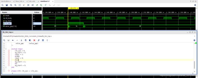
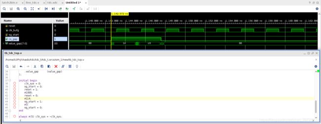
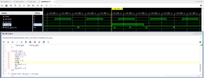
6、后仿真测试结果


7、以上可以对sg_start和clk_bufg两个信号的间隔进行大致估算,通过计算大致可计算出第一级carry4输入的延时。