ESP32 different boot modes hardware requirements
The ESP32 chips usually has two boot modes:Flash download mode and SPI Flash boot mode .
- Different boot modes all focuses on the level of the Strapping pins when the chips powered on.
- Different boot modes has different hardware requirements when the chips powered on
Flash download mode
Different models of the ESP32 series chips, the hardware interface used to download firmware is exactly the same, and they all use the UART0(
TXD0(GPIO1)andRXD0(GPIO3)) interface to download firmware.
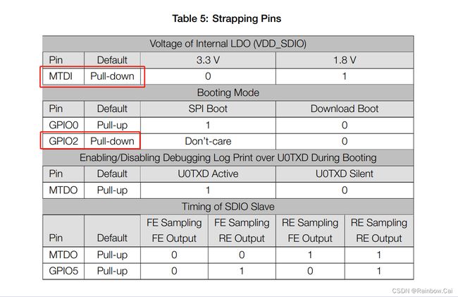
If you want to download the firmware, the chips will need to enter the download mode when powered on. The following hardware conditions need to be satisfied to enter the download mode when the chips power on . Please refer to the 《ESP32 Datasheet》 about “Strapping Pins” instructions . As follows:
- We recommend connecting
GPIO0to GND before powering on.- The
GPIO2andMTDI(GPIO12)arelow levelby default when the chips powered on if they are not used for other functions.- If you are using the
3.3V Flash, it require theMTDI(GPIO12)pin to below levelwhen the chips powered on. If you are using the1.8V flash, it require theMTDI(GPIO12)pin to be high level when the chips powered on.
Generally, we recommended to check the boot log of chip UART0 to determine whether the chip is in download mode when the power-on. If it is in download mode, the following log will be printed:
ets Jun  8 2016 00:22:57
rst:0x1 (POWERON_RESET),boot:0x3 (DOWNLOAD_BOOT(UART0/UART1/SDIO_REI_REO_V2))
waiting for download
You can use the serial debugging tool to view the logs.

By viewing the boot parameters in the chip startup log, you can also determine the true level state of the Strapping pins when it is powered on.
-
You can refer to the ESP32 “Boot log” instructions
-
The Strapping pins bits corresponding to ESP32 series Boot logs are as follows:
| bit 5 | bit 4 | bit 3 | bit 2 | bit 1 | bit 0 |
|---|---|---|---|---|---|
GPIO 12(MTDI) |
GPIO 0 |
GPIO 2 |
GPIO 4 |
GPIO 15(MTDO) |
GPIO 5 |
boot:0xNN (DESCRIPTION) is the hex value of the strapping pins, as represented in the GPIO_STRAP register. The individual bit values are as follows:
0x01 :GPIO5
0x02 :MTDO (GPIO15)
0x04 :GPIO4
0x08 :GPIO2
0x10 :GPIO0
0x20 :MTDI (GPIO12)
It is worth mentioning our ESP32-devkit-C development board has the automatic download circuit, so you do not need to manually enter the download mode when the chips power on. You only need to connect the USB port to the PC. You can refer to the schematic design of the ESP32-DevKitC V4 schematics development board.
SPI Flash boot mode to run the firmware
If you want to run the firmware, the chips will need to enter the SPI Flash boot mode when powered on. The Strapping pins level meets SPI Flash boot mode requirements by default when the chip is powered on. Therefore, you only need to power on the chip properly and meet the power-up timing. Please note that the power-on timing of EN pin is later than of the VDD. The power-up timing requires that when VDD reaches 2.3V, EN cannot exceed 0.6V. Please refer to the 《ESP32 Datasheet》 about the “Figure 5: ESP32 Power-up and Reset Timing” . For more hardware instructions, please refer to the 《ESP32 Hardware Design Guidelines》 .
If you want to run your firmware after downloading it, please remember to pull-up the GPIO0 and do a hardware reset. Pulling down the EN pin can triggers a hardware reset and restart.
The following hardware conditions need to be satisfied to enter the SPI Flash boot mode when the chips power on . Please refer to the 《ESP32 Datasheet》 about “Strapping Pins” instructions . As follows:
MTDI(GPIO12)-> Pull Down
VDD -> 3V3
GND -> GND
EN -> Pull UP
GPIO0 -> Pull UP(Enter the Flash boot mode)
TXD0 、RXD0 (Correct Connection)
