一、什么是宏函数?通过宏定义的函数是宏函数。如下,编译器在预处理阶段会将Add(x,y)替换为((x)*(y))#defineAdd(x,y)((x)*(y))#defineAdd(x,y)((x)*(y))intmain(){inta=10;intb=20;intd=10;intc=Add(a+d,b)*2;cout<
谢谢你们,爱你们!
鹿游儿
昨天家人去泡温泉,二个孩子也带着去,出发前一晚,匆匆下班,赶回家和孩子一起收拾。饭后,我拿出笔和本子(上次去澳门时做手帐的本子)写下了1\2\3\4\5\6\7\8\9,让后让小壹去思考,带什么出发去旅游呢?她在对应的数字旁边画上了,泳衣、泳圈、肖恩、内衣内裤、tapuy、拖鞋……画完后,就让她自己对着这个本子,将要带的,一一带上,没想到这次带的书还是这本《便便工厂》(晚上姑婆发照片过来,妹妹累得
C语言如何定义宏函数?
小九格物
c语言
在C语言中,宏函数是通过预处理器定义的,它在编译之前替换代码中的宏调用。宏函数可以模拟函数的行为,但它们不是真正的函数,因为它们在编译时不会进行类型检查,也不会分配存储空间。宏函数的定义通常使用#define指令,后面跟着宏的名称和参数列表,以及宏展开后的代码。宏函数的定义方式:1.基本宏函数:这是最简单的宏函数形式,它直接定义一个表达式。#defineSQUARE(x)((x)*(x))2.带参
微服务下功能权限与数据权限的设计与实现
nbsaas-boot
微服务java架构
在微服务架构下,系统的功能权限和数据权限控制显得尤为重要。随着系统规模的扩大和微服务数量的增加,如何保证不同用户和服务之间的访问权限准确、细粒度地控制,成为设计安全策略的关键。本文将讨论如何在微服务体系中设计和实现功能权限与数据权限控制。1.功能权限与数据权限的定义功能权限:指用户或系统角色对特定功能的访问权限。通常是某个用户角色能否执行某个操作,比如查看订单、创建订单、修改用户资料等。数据权限:
理解Gunicorn:Python WSGI服务器的基石
范范0825
ipythonlinux运维
理解Gunicorn:PythonWSGI服务器的基石介绍Gunicorn,全称GreenUnicorn,是一个为PythonWSGI(WebServerGatewayInterface)应用设计的高效、轻量级HTTP服务器。作为PythonWeb应用部署的常用工具,Gunicorn以其高性能和易用性著称。本文将介绍Gunicorn的基本概念、安装和配置,帮助初学者快速上手。1.什么是Gunico
c++ 的iostream 和 c++的stdio的区别和联系
黄卷青灯77
c++算法开发语言iostreamstdio
在C++中,iostream和C语言的stdio.h都是用于处理输入输出的库,但它们在设计、用法和功能上有许多不同。以下是两者的区别和联系:区别1.编程风格iostream(C++风格):C++标准库中的输入输出流类库,支持面向对象的输入输出操作。典型用法是cin(输入)和cout(输出),使用>操作符来处理数据。更加类型安全,支持用户自定义类型的输入输出。#includeintmain(){in
Long类型前后端数据不一致
igotyback
前端
响应给前端的数据浏览器控制台中response中看到的Long类型的数据是正常的到前端数据不一致前后端数据类型不匹配是一个常见问题,尤其是当后端使用Java的Long类型(64位)与前端JavaScript的Number类型(最大安全整数为2^53-1,即16位)进行数据交互时,很容易出现精度丢失的问题。这是因为JavaScript中的Number类型无法安全地表示超过16位的整数。为了解决这个问
消息中间件有哪些常见类型
xmh-sxh-1314
java
消息中间件根据其设计理念和用途,可以大致分为以下几种常见类型:点对点消息队列(Point-to-PointMessagingQueues):在这种模型中,消息被发送到特定的队列中,消费者从队列中取出并处理消息。队列中的消息只能被一个消费者消费,消费后即被删除。常见的实现包括IBM的MQSeries、RabbitMQ的部分使用场景等。适用于任务分发、负载均衡等场景。发布/订阅消息模型(Pub/Sub
【一起学Rust | 设计模式】习惯语法——使用借用类型作为参数、格式化拼接字符串、构造函数
广龙宇
一起学Rust#Rust设计模式rust设计模式开发语言
提示:文章写完后,目录可以自动生成,如何生成可参考右边的帮助文档文章目录前言一、使用借用类型作为参数二、格式化拼接字符串三、使用构造函数总结前言Rust不是传统的面向对象编程语言,它的所有特性,使其独一无二。因此,学习特定于Rust的设计模式是必要的。本系列文章为作者学习《Rust设计模式》的学习笔记以及自己的见解。因此,本系列文章的结构也与此书的结构相同(后续可能会调成结构),基本上分为三个部分
每日一题——第八十九题
互联网打工人no1
C语言程序设计每日一练c语言
题目:在字符串中找到提取数字,并统计一共找到多少整数,a123xxyu23&8889,那么找到的整数为123,23,8889//思想:#include#include#includeintmain(){charstr[]="a123xxyu23&8889";intcount=0;intnum=0;//用于临时存放当前正在构建的整数。boolinNum=false;//用于标记当前是否正在读取一个整
每日一题——第八十三题
互联网打工人no1
C语言程序设计每日一练c语言
题目:将输入的整形数字输出,输出1990,输出"1990"#include#defineMAX_INPUT1024intmain(){intarrr_num[MAX_INPUT];intnum,i=0;printf("请输入一个数字:");scanf_s("%d",&num);while(num!=0){arrr_num[i++]=num%10;num/=10;}printf("\"");for(
腾讯云技术深度探索:构建高效云原生微服务架构
我的运维人生
云原生架构腾讯云运维开发技术共享
腾讯云技术深度探索:构建高效云原生微服务架构在当今快速发展的技术环境中,云原生技术已成为企业数字化转型的关键驱动力。腾讯云作为行业领先的云服务提供商,不断推出创新的产品和技术,助力企业构建高效、可扩展的云原生微服务架构。本文将深入探讨腾讯云在微服务领域的最新进展,并通过一个实际案例展示如何在腾讯云平台上构建云原生应用。腾讯云微服务架构概览腾讯云微服务架构基于云原生理念,旨在帮助企业快速实现应用的容
Google earth studio 简介
陟彼高冈yu
旅游
GoogleEarthStudio是一个基于Web的动画工具,专为创作使用GoogleEarth数据的动画和视频而设计。它利用了GoogleEarth强大的三维地图和卫星影像数据库,使用户能够轻松地创建逼真的地球动画、航拍视频和动态地图可视化。网址为https://www.google.com/earth/studio/。GoogleEarthStudio是一个基于Web的动画工具,专为创作使用G
509. 斐波那契数(每日一题)
lzyprime
lzyprime博客(github)创建时间:2021.01.04qq及邮箱:2383518170leetcode笔记题目描述斐波那契数,通常用F(n)表示,形成的序列称为斐波那契数列。该数列由0和1开始,后面的每一项数字都是前面两项数字的和。也就是:F(0)=0,F(1)=1F(n)=F(n-1)+F(n-2),其中n>1给你n,请计算F(n)。示例1:输入:2输出:1解释:F(2)=F(1)+
使用 FinalShell 进行远程连接(ssh 远程连接 Linux 服务器)
编程经验分享
开发工具服务器sshlinux
目录前言基本使用教程新建远程连接连接主机自定义命令路由追踪前言后端开发,必然需要和服务器打交道,部署应用,排查问题,查看运行日志等等。一般服务器都是集中部署在机房中,也有一些直接是云服务器,总而言之,程序员不可能直接和服务器直接操作,一般都是通过ssh连接来登录服务器。刚接触远程连接时,使用的是XSHELL来远程连接服务器,连接上就能够操作远程服务器了,但是仅用XSHELL并没有上传下载文件的功能
DIV+CSS+JavaScript技术制作网页(旅游主题网页设计与制作)云南大理
STU学生网页设计
网页设计期末网页作业html静态网页html5期末大作业网页设计web大作业
️精彩专栏推荐作者主页:【进入主页—获取更多源码】web前端期末大作业:【HTML5网页期末作业(1000套)】程序员有趣的告白方式:【HTML七夕情人节表白网页制作(110套)】文章目录二、网站介绍三、网站效果▶️1.视频演示2.图片演示四、网站代码HTML结构代码CSS样式代码五、更多源码二、网站介绍网站布局方面:计划采用目前主流的、能兼容各大主流浏览器、显示效果稳定的浮动网页布局结构。网站程
关于城市旅游的HTML网页设计——(旅游风景云南 5页)HTML+CSS+JavaScript
二挡起步
web前端期末大作业javascripthtmlcss旅游风景
⛵源码获取文末联系✈Web前端开发技术描述网页设计题材,DIV+CSS布局制作,HTML+CSS网页设计期末课程大作业|游景点介绍|旅游风景区|家乡介绍|等网站的设计与制作|HTML期末大学生网页设计作业,Web大学生网页HTML:结构CSS:样式在操作方面上运用了html5和css3,采用了div+css结构、表单、超链接、浮动、绝对定位、相对定位、字体样式、引用视频等基础知识JavaScrip
HTML网页设计制作大作业(div+css) 云南我的家乡旅游景点 带文字滚动
二挡起步
web前端期末大作业web设计网页规划与设计htmlcssjavascriptdreamweaver前端
Web前端开发技术描述网页设计题材,DIV+CSS布局制作,HTML+CSS网页设计期末课程大作业游景点介绍|旅游风景区|家乡介绍|等网站的设计与制作HTML期末大学生网页设计作业HTML:结构CSS:样式在操作方面上运用了html5和css3,采用了div+css结构、表单、超链接、浮动、绝对定位、相对定位、字体样式、引用视频等基础知识JavaScript:做与用户的交互行为文章目录前端学习路线
121. 买卖股票的最佳时机
薄荷糖的味道_fb40
给定一个数组,它的第i个元素是一支给定股票第i天的价格。如果你最多只允许完成一笔交易(即买入和卖出一支股票),设计一个算法来计算你所能获取的最大利润。注意你不能在买入股票前卖出股票。示例1:输入:[7,1,5,3,6,4]输出:5解释:在第2天(股票价格=1)的时候买入,在第5天(股票价格=6)的时候卖出,最大利润=6-1=5。注意利润不能是7-1=6,因为卖出价格需要大于买入价格。示例2:输入:
【JS】执行时长(100分) |思路参考+代码解析(C++)
l939035548
JS算法数据结构c++
题目为了充分发挥GPU算力,需要尽可能多的将任务交给GPU执行,现在有一个任务数组,数组元素表示在这1秒内新增的任务个数且每秒都有新增任务。假设GPU最多一次执行n个任务,一次执行耗时1秒,在保证GPU不空闲情况下,最少需要多长时间执行完成。题目输入第一个参数为GPU一次最多执行的任务个数,取值范围[1,10000]第二个参数为任务数组长度,取值范围[1,10000]第三个参数为任务数组,数字范围
CX8903:Ebike自行车仪表电源方案开发,Ebike智能仪表电源芯片
诚芯微科技
社交电子
CX8903:电动Ebike自行车仪表电源方案开发,Ebike智能仪表电源芯片推荐。电动助力自行车EBIKE凭借其环保、健康、低噪、和便捷等特点,成为了越来越受欢迎的骑行便利交通工具。提供电动Ebike自行车仪表电源方案开发、E-BIKE电动助力自行车仪表供电电源解决方案。CX8903采用100V高压制造工艺(芯片最高耐压可到100V以上),SOP-8L贴片封装,CX8903内置100V/90mΩ
CX8836:小体积大功率升降压方案推荐(附Demo设计指南)
诚芯微科技
社交电子
CX8836是一颗同步四开关单向升降压控制器,在4.5V-40V宽输入电压范围内稳定工作,持续负载电流10A,能够在输入高于或低于输出电压时稳定调节输出电压,可适用于USBPD快充、车载充电器、HUB、汽车启停系统、工业PC电源等多种升降压应用场合,为大功率TYPE-CPD车载充电器提供最优解决方案。提供CX8836Demo测试、CX8836样品申请及CX8836方案开发技术支持。CX8836同升
数据仓库——维度表一致性
墨染丶eye
背诵数据仓库
数据仓库基础笔记思维导图已经整理完毕,完整连接为:数据仓库基础知识笔记思维导图维度一致性问题从逻辑层面来看,当一系列星型模型共享一组公共维度时,所涉及的维度称为一致性维度。当维度表存在不一致时,短期的成功难以弥补长期的错误。维度时确保不同过程中信息集成起来实现横向钻取货活动的关键。造成横向钻取失败的原因维度结构的差别,因为维度的差别,分析工作涉及的领域从简单到复杂,但是都是通过复杂的报表来弥补设计
高级 ECharts 技巧:自定义图表主题与样式
SnowMan1993
echarts信息可视化数据分析
ECharts是一个强大的数据可视化库,提供了多种内置主题和样式,但你也可以根据项目的设计需求,自定义图表的主题与样式。本文将介绍如何使用ECharts自定义图表主题,以提升数据可视化的吸引力和一致性。1.什么是ECharts主题?ECharts的主题是指定义图表样式的配置项,包括颜色、字体、线条样式等。通过预设主题,你可以快速更改图表的整体风格,而自定义主题则允许你在此基础上进行个性化设置。2.
Redis系列:Geo 类型赋能亿级地图位置计算
Ly768768
redisbootstrap数据库
1前言我们在篇深刻理解高性能Redis的本质的时候就介绍过Redis的几种基本数据结构,它是基于不同业务场景而设计的:动态字符串(REDIS_STRING):整数(REDIS_ENCODING_INT)、字符串(REDIS_ENCODING_RAW)双端列表(REDIS_ENCODING_LINKEDLIST)压缩列表(REDIS_ENCODING_ZIPLIST)跳跃表(REDIS_ENCODI
ARM驱动学习之基础小知识
JT灬新一
ARM嵌入式arm开发学习
ARM驱动学习之基础小知识•sch原理图工程师工作内容–方案–元器件选型–采购(能不能买到,价格)–原理图(涉及到稳定性)•layout画板工程师–layout(封装、布局,布线,log)(涉及到稳定性)–焊接的一部分工作(调试阶段板子的焊接)•驱动工程师–驱动,原理图,layout三部分的交集容易发生矛盾•PCB研发流程介绍–方案,原理图(网表)–layout工程师(gerber文件)–PCB板
ARM驱动学习之5 LEDS驱动
JT灬新一
嵌入式C底层arm开发学习单片机
ARM驱动学习之5LEDS驱动知识点:•linuxGPIO申请函数和赋值函数–gpio_request–gpio_set_value•三星平台配置GPIO函数–s3c_gpio_cfgpin•GPIO配置输出模式的宏变量–S3C_GPIO_OUTPUT注意点:DRIVER_NAME和DEVICE_NAME匹配。实现步骤:1.加入需要的头文件://Linux平台的gpio头文件#include//三
Low Power概念介绍-Voltage Area
飞奔的大虎
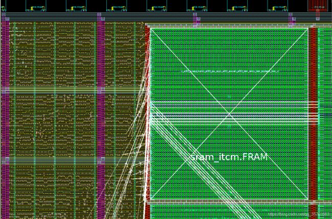
随着智能手机,以及物联网的普及,芯片功耗的问题最近几年得到了越来越多的重视。为了实现集成电路的低功耗设计目标,我们需要在系统设计阶段就采用低功耗设计的方案。而且,随着设计流程的逐步推进,到了芯片后端设计阶段,降低芯片功耗的方法已经很少了,节省的功耗百分比也不断下降。芯片的功耗主要由静态功耗(staticleakagepower)和动态功耗(dynamicpower)构成。静态功耗主要是指电路处于等
SQL的各种连接查询
xieke90
UNION ALLUNION外连接内连接JOIN
一、内连接
概念:内连接就是使用比较运算符根据每个表共有的列的值匹配两个表中的行。
内连接(join 或者inner join )
SQL语法:
select * fron
java编程思想--复用类
百合不是茶
java继承代理组合final类
复用类看着标题都不知道是什么,再加上java编程思想翻译的比价难懂,所以知道现在才看这本软件界的奇书
一:组合语法:就是将对象的引用放到新类中即可
代码:
package com.wj.reuse;
/**
*
* @author Administrator 组
[开源与生态系统]国产CPU的生态系统
comsci
cpu
计算机要从娃娃抓起...而孩子最喜欢玩游戏....
要让国产CPU在国内市场形成自己的生态系统和产业链,国家和企业就不能够忘记游戏这个非常关键的环节....
投入一些资金和资源,人力和政策,让游
JVM内存区域划分Eden Space、Survivor Space、Tenured Gen,Perm Gen解释
商人shang
jvm内存
jvm区域总体分两类,heap区和非heap区。heap区又分:Eden Space(伊甸园)、Survivor Space(幸存者区)、Tenured Gen(老年代-养老区)。 非heap区又分:Code Cache(代码缓存区)、Perm Gen(永久代)、Jvm Stack(java虚拟机栈)、Local Method Statck(本地方法栈)。
HotSpot虚拟机GC算法采用分代收
页面上调用 QQ
oloz
qq
<A href="tencent://message/?uin=707321921&Site=有事Q我&Menu=yes">
<img style="border:0px;" src=http://wpa.qq.com/pa?p=1:707321921:1></a>
一些问题
文强chu
问题
1.eclipse 导出 doc 出现“The Javadoc command does not exist.” javadoc command 选择 jdk/bin/javadoc.exe 2.tomcate 配置 web 项目 .....
SQL:3.mysql * 必须得放前面 否则 select&nbs
生活没有安全感
小桔子
生活孤独安全感
圈子好小,身边朋友没几个,交心的更是少之又少。在深圳,除了男朋友,没几个亲密的人。不知不觉男朋友成了唯一的依靠,毫不夸张的说,业余生活的全部。现在感情好,也很幸福的。但是说不准难免人心会变嘛,不发生什么大家都乐融融,发生什么很难处理。我想说如果不幸被分手(无论原因如何),生活难免变化很大,在深圳,我没交心的朋友。明
php 基础语法
aichenglong
php 基本语法
1 .1 php变量必须以$开头
<?php
$a=” b”;
echo
?>
1 .2 php基本数据库类型 Integer float/double Boolean string
1 .3 复合数据类型 数组array和对象 object
1 .4 特殊数据类型 null 资源类型(resource) $co
mybatis tools 配置详解
AILIKES
mybatis
MyBatis Generator中文文档
MyBatis Generator中文文档地址:
http://generator.sturgeon.mopaas.com/
该中文文档由于尽可能和原文内容一致,所以有些地方如果不熟悉,看中文版的文档的也会有一定的障碍,所以本章根据该中文文档以及实际应用,使用通俗的语言来讲解详细的配置。
本文使用Markdown进行编辑,但是博客显示效
继承与多态的探讨
百合不是茶
JAVA面向对象 继承 对象
继承 extends 多态
继承是面向对象最经常使用的特征之一:继承语法是通过继承发、基类的域和方法 //继承就是从现有的类中生成一个新的类,这个新类拥有现有类的所有extends是使用继承的关键字:
在A类中定义属性和方法;
class A{
//定义属性
int age;
//定义方法
public void go
JS的undefined与null的实例
bijian1013
JavaScriptJavaScript
<form name="theform" id="theform">
</form>
<script language="javascript">
var a
alert(typeof(b)); //这里提示undefined
if(theform.datas
TDD实践(一)
bijian1013
java敏捷TDD
一.TDD概述
TDD:测试驱动开发,它的基本思想就是在开发功能代码之前,先编写测试代码。也就是说在明确要开发某个功能后,首先思考如何对这个功能进行测试,并完成测试代码的编写,然后编写相关的代码满足这些测试用例。然后循环进行添加其他功能,直到完全部功能的开发。
[Maven学习笔记十]Maven Profile与资源文件过滤器
bit1129
maven
什么是Maven Profile
Maven Profile的含义是针对编译打包环境和编译打包目的配置定制,可以在不同的环境上选择相应的配置,例如DB信息,可以根据是为开发环境编译打包,还是为生产环境编译打包,动态的选择正确的DB配置信息
Profile的激活机制
1.Profile可以手工激活,比如在Intellij Idea的Maven Project视图中可以选择一个P
【Hive八】Hive用户自定义生成表函数(UDTF)
bit1129
hive
1. 什么是UDTF
UDTF,是User Defined Table-Generating Functions,一眼看上去,貌似是用户自定义生成表函数,这个生成表不应该理解为生成了一个HQL Table, 貌似更应该理解为生成了类似关系表的二维行数据集
2. 如何实现UDTF
继承org.apache.hadoop.hive.ql.udf.generic
tfs restful api 加auth 2.0认计
ronin47
目前思考如何给tfs的ngx-tfs api增加安全性。有如下两点:
一是基于客户端的ip设置。这个比较容易实现。
二是基于OAuth2.0认证,这个需要lua,实现起来相对于一来说,有些难度。
现在重点介绍第二种方法实现思路。
前言:我们使用Nginx的Lua中间件建立了OAuth2认证和授权层。如果你也有此打算,阅读下面的文档,实现自动化并获得收益。SeatGe
jdk环境变量配置
byalias
javajdk
进行java开发,首先要安装jdk,安装了jdk后还要进行环境变量配置:
1、下载jdk(http://java.sun.com/javase/downloads/index.jsp),我下载的版本是:jdk-7u79-windows-x64.exe
2、安装jdk-7u79-windows-x64.exe
3、配置环境变量:右击"计算机"-->&quo
《代码大全》表驱动法-Table Driven Approach-2
bylijinnan
java
package com.ljn.base;
import java.io.BufferedReader;
import java.io.FileInputStream;
import java.io.InputStreamReader;
import java.util.ArrayList;
import java.util.Collections;
import java.uti
SQL 数值四舍五入 小数点后保留2位
chicony
四舍五入
1.round() 函数是四舍五入用,第一个参数是我们要被操作的数据,第二个参数是设置我们四舍五入之后小数点后显示几位。
2.numeric 函数的2个参数,第一个表示数据长度,第二个参数表示小数点后位数。
例如:
select cast(round(12.5,2) as numeric(5,2))
c++运算符重载
CrazyMizzz
C++
一、加+,减-,乘*,除/ 的运算符重载
Rational operator*(const Rational &x) const{
return Rational(x.a * this->a);
}
在这里只写乘法的,加减除的写法类似
二、<<输出,>>输入的运算符重载
&nb
hive DDL语法汇总
daizj
hive修改列DDL修改表
hive DDL语法汇总
1、对表重命名
hive> ALTER TABLE table_name RENAME TO new_table_name;
2、修改表备注
hive> ALTER TABLE table_name SET TBLPROPERTIES ('comment' = new_comm
jbox使用说明
dcj3sjt126com
Web
参考网址:http://www.kudystudio.com/jbox/jbox-demo.html jBox v2.3 beta [
点击下载]
技术交流QQGroup:172543951 100521167
[2011-11-11] jBox v2.3 正式版
- [调整&修复] IE6下有iframe或页面有active、applet控件
UISegmentedControl 开发笔记
dcj3sjt126com
// typedef NS_ENUM(NSInteger, UISegmentedControlStyle) {
// UISegmentedControlStylePlain, // large plain
&
Slick生成表映射文件
ekian
scala
Scala添加SLICK进行数据库操作,需在sbt文件上添加slick-codegen包
"com.typesafe.slick" %% "slick-codegen" % slickVersion
因为我是连接SQL Server数据库,还需添加slick-extensions,jtds包
"com.typesa
ES-TEST
gengzg
test
package com.MarkNum;
import java.io.IOException;
import java.util.Date;
import java.util.HashMap;
import java.util.Map;
import javax.servlet.ServletException;
import javax.servlet.annotation
为何外键不再推荐使用
hugh.wang
mysqlDB
表的关联,是一种逻辑关系,并不需要进行物理上的“硬关联”,而且你所期望的关联,其实只是其数据上存在一定的联系而已,而这种联系实际上是在设计之初就定义好的固有逻辑。
在业务代码中实现的时候,只要按照设计之初的这种固有关联逻辑来处理数据即可,并不需要在数据库层面进行“硬关联”,因为在数据库层面通过使用外键的方式进行“硬关联”,会带来很多额外的资源消耗来进行一致性和完整性校验,即使很多时候我们并不
领域驱动设计
julyflame
VODAO设计模式DTOpo
概念:
VO(View Object):视图对象,用于展示层,它的作用是把某个指定页面(或组件)的所有数据封装起来。
DTO(Data Transfer Object):数据传输对象,这个概念来源于J2EE的设计模式,原来的目的是为了EJB的分布式应用提供粗粒度的数据实体,以减少分布式调用的次数,从而提高分布式调用的性能和降低网络负载,但在这里,我泛指用于展示层与服务层之间的数据传输对
单例设计模式
hm4123660
javaSingleton单例设计模式懒汉式饿汉式
单例模式是一种常用的软件设计模式。在它的核心结构中只包含一个被称为单例类的特殊类。通过单例模式可以保证系统中一个类只有一个实例而且该实例易于外界访问,从而方便对实例个数的控制并节约系统源。如果希望在系统中某个类的对象只能存在一个,单例模式是最好的解决方案。
&nb
logback
zhb8015
loglogback
一、logback的介绍
Logback是由log4j创始人设计的又一个开源日志组件。logback当前分成三个模块:logback-core,logback- classic和logback-access。logback-core是其它两个模块的基础模块。logback-classic是log4j的一个 改良版本。此外logback-class
整合Kafka到Spark Streaming——代码示例和挑战
Stark_Summer
sparkstormzookeeperPARALLELISMprocessing
作者Michael G. Noll是瑞士的一位工程师和研究员,效力于Verisign,是Verisign实验室的大规模数据分析基础设施(基础Hadoop)的技术主管。本文,Michael详细的演示了如何将Kafka整合到Spark Streaming中。 期间, Michael还提到了将Kafka整合到 Spark Streaming中的一些现状,非常值得阅读,虽然有一些信息在Spark 1.2版
spring-master-slave-commondao
王新春
DAOspringdataSourceslavemaster
互联网的web项目,都有个特点:请求的并发量高,其中请求最耗时的db操作,又是系统优化的重中之重。
为此,往往搭建 db的 一主多从库的 数据库架构。作为web的DAO层,要保证针对主库进行写操作,对多个从库进行读操作。当然在一些请求中,为了避免主从复制的延迟导致的数据不一致性,部分的读操作也要到主库上。(这种需求一般通过业务垂直分开,比如下单业务的代码所部署的机器,读去应该也要从主库读取数


