FFT算法
FFT算法的完整DSP实现
傅里叶变换或者FFT的理论参考:
[1] http://www.dspguide.com/ch12/2.htm
The Scientist and Engineer's Guide to Digital Signal Processing, By Steven W. Smith, Ph.D.
[2] http://blog.csdn.net/v_JULY_v/article/details/6196862,可当作[1]的中文参考
[3] 任意一本数字信号处理教材,上面都有详细的推导DCT求解转换为FFT求解的过程
[4] TI文档:基于TMS320C64x+DSP的FFT实现。 使用baidu/google可以搜索到。
1. 有关FFT理论的一点小小解释
关于FFT这里只想提到两点:
(1)DFT变换对的表达式(必须记住)
![]() —— 称旋转因子
—— 称旋转因子
(2)FFT用途——目标只有一个,加速DFT的计算效率。
DFT计算X(k)需要N^2次复数乘法和N(N-1)次复数加法;FFT将N^2的计算量降为![]() 。
。
“FFT其实是很难的东西,即使常年在这个领域下打拼的科学家也未必能很好的写出FFT的算法。”——摘自参考上面提供的参考文献[1]
因此,我们不必太过纠结于细节,当明白FFT理论后,将已有的算法挪过来用就OK了,不必为闭着教材写不出FFT而郁闷不堪。
FFT的BASIC程序伪代码如下:
IFFT的BASIC程序伪代码如下(IFFT通过调用FFT计算):
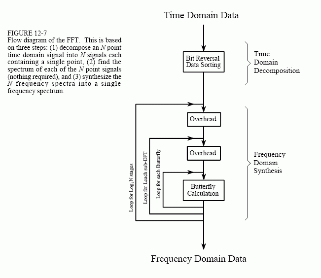
FFT算法的流程图如下图,总结为3过程3循环:
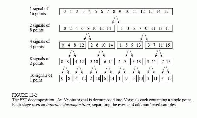
(1)3过程:单点时域分解(倒位序过程) + 单点时域计算单点频谱 + 频域合成
(2)3循环:外循环——分解次数,中循环——sub-DFT运算,内循环——2点蝶形算法
2. FFT的DSP实现
下面为本人使用C语言实现的FFT及IFFT算法实例,能计算任意以2为对数底的采样点数的FFT,算法参考上面给的流程图。
/*
 * zx_fft.h
 *
 *  Created on: 2013-8-5
 *      Author: monkeyzx
 */

#ifndef ZX_FFT_H_
#define ZX_FFT_H_

typedef float          FFT_TYPE;

#ifndef PI
#define PI             (3.14159265f)
#endif

typedef struct complex_st {
	FFT_TYPE real;
	FFT_TYPE img;
} complex;

int fft(complex *x, int N);
int ifft(complex *x, int N);
void zx_fft(void);

#endif /* ZX_FFT_H_ */
/*
 * zx_fft.c
 *
 * Implementation of Fast Fourier Transform(FFT)
 * and reversal Fast Fourier Transform(IFFT)
 *
 *  Created on: 2013-8-5
 *      Author: monkeyzx
 */

#include "zx_fft.h"
#include <math.h>
#include <stdlib.h>

/*
 * Bit Reverse
 * === Input ===
 * x : complex numbers
 * n : nodes of FFT. @N should be power of 2, that is 2^(*)
 * l : count by bit of binary format, @l=CEIL{log2(n)}
 * === Output ===
 * r : results after reversed.
 * Note: I use a local variable @temp that result @r can be set
 * to @x and won't overlap.
 */
static void BitReverse(complex *x, complex *r, int n, int l)
{
	int i = 0;
	int j = 0;
	short stk = 0;
	static complex *temp = 0;

	temp = (complex *)malloc(sizeof(complex) * n);
	if (!temp) {
		return;
	}

	for(i=0; i<n; i++) {
		stk = 0;
		j = 0;
		do {
			stk |= (i>>(j++)) & 0x01;
			if(j<l)
			{
				stk <<= 1;
			}
		}while(j<l);

		if(stk < n) {             /* 满足倒位序输出 */
			temp[stk] = x[i];
		}
	}
	/* copy @temp to @r */
	for (i=0; i<n; i++) {
		r[i] = temp[i];
	}
	free(temp);
}

/*
 * FFT Algorithm
 * === Inputs ===
 * x : complex numbers
 * N : nodes of FFT. @N should be power of 2, that is 2^(*)
 * === Output ===
 * the @x contains the result of FFT algorithm, so the original data
 * in @x is destroyed, please store them before using FFT.
 */
int fft(complex *x, int N)
{
	int i,j,l,ip;
	static int M = 0;
	static int le,le2;
	static FFT_TYPE sR,sI,tR,tI,uR,uI;

	M = (int)(log(N) / log(2));

	/*
	 * bit reversal sorting
	 */
	BitReverse(x,x,N,M);

	/*
	 * For Loops
	 */
	for (l=1; l<=M; l++) {   /* loop for ceil{log2(N)} */
		le = (int)pow(2,l);
		le2 = (int)(le / 2);
		uR = 1;
		uI = 0;
		sR = cos(PI / le2);
		sI = -sin(PI / le2);
		for (j=1; j<=le2; j++) {   /* loop for each sub DFT */
			//jm1 = j - 1;
			for (i=j-1; i<=N-1; i+=le) {  /* loop for each butterfly */
				ip = i + le2;
				tR = x[ip].real * uR - x[ip].img * uI;
				tI = x[ip].real * uI + x[ip].img * uR;
				x[ip].real = x[i].real - tR;
				x[ip].img = x[i].img - tI;
				x[i].real += tR;
				x[i].img += tI;
			}  /* Next i */
			tR = uR;
			uR = tR * sR - uI * sI;
			uI = tR * sI + uI *sR;
		} /* Next j */
	} /* Next l */

	return 0;
}

/*
 * Inverse FFT Algorithm
 * === Inputs ===
 * x : complex numbers
 * N : nodes of FFT. @N should be power of 2, that is 2^(*)
 * === Output ===
 * the @x contains the result of FFT algorithm, so the original data
 * in @x is destroyed, please store them before using FFT.
 */
int ifft(complex *x, int N)
{
	int k = 0;

	for (k=0; k<=N-1; k++) {
		x[k].img = -x[k].img;
	}

	fft(x, N);    /* using FFT */

	for (k=0; k<=N-1; k++) {
		x[k].real = x[k].real / N;
		x[k].img = -x[k].img / N;
	}

	return 0;
}

/*
 * Code below is an example of using FFT and IFFT.
 */
#define  SAMPLE_NODES              (128)
complex x[SAMPLE_NODES];
int INPUT[SAMPLE_NODES];
int OUTPUT[SAMPLE_NODES];

static void MakeInput()
{
	int i;

	for ( i=0;i<SAMPLE_NODES;i++ )
	{
		x[i].real = sin(PI*2*i/SAMPLE_NODES);
		x[i].img = 0.0f;
		INPUT[i]=sin(PI*2*i/SAMPLE_NODES)*1024;
	}
}

static void MakeOutput()
{
	int i;

	for ( i=0;i<SAMPLE_NODES;i++ )
	{
		OUTPUT[i] = sqrt(x[i].real*x[i].real + x[i].img*x[i].img)*1024;
	}
}

void zx_fft(void)
{
	MakeInput();

	fft(x,128);
	MakeOutput();

	ifft(x,128);
	MakeOutput();
}
程序在TMS320C6713上实验,主函数中调用zx_fft()函数即可。
FFT的采样点数为128,输入信号的实数域为正弦信号,虚数域为0,数据精度定义FFT_TYPE为float类型,MakeInput和MakeOutput函数分别用于产生输入数据INPUT和输出数据OUTPUT的函数,便于使用CCS 的Graph功能绘制波形图。这里调试时使用CCS v5中的Tools -> Graph功能得到下面的波形图(怎么用自己琢磨,不会的使用CCS 的Help)。
输入波形
输入信号的频域幅值表示
FFT运算结果
对FFT运算结果逆变换(IFFT)
如何检验运算结果是否正确呢?有几种方法:
(1)使用matlab验证,下面为相同情况的matlab图形验证代码
SAMPLE_NODES = 128;
i = 1:SAMPLE_NODES;
x = sin(pi*2*i / SAMPLE_NODES);

subplot(2,2,1); plot(x);title('Inputs');
axis([0 128 -1 1]);

y = fft(x, SAMPLE_NODES);
subplot(2,2,2); plot(abs(y));title('FFT');
axis([0 128 0 80]);

z = ifft(y, SAMPLE_NODES);
subplot(2,2,3); plot(abs(z));title('IFFT');
axis([0 128 0 1]);
(2)使用IFFT验证:输入信号的FFT获得的信号再IFFT,则的到的信号与原信号相同
可能大家发现输入信号上面的最后IFFT的信号似乎不同,这是因为FFT和IFFT存在精度截断误差(也叫数据截断噪声,意思就是说,我们使用的float数据类型数据位数有限,没法完全保留原始信号的信息)。因此,IFFT之后是复数(数据截断噪声引入了虚数域,只不过值很小),所以在绘图时使用了计算幅值的方法,
C代码中:
OUTPUT[i] = sqrt(x[i].real*x[i].real + x[i].img*x[i].img)*1024;
matlab代码中:
subplot(2,2,3); plot(abs(z));title('IFFT');
所以IFFT的结果将sin函数的负y轴数据翻到了正y轴。另外,在CCS v5的图形中我们将显示信号的幅度放大了1024倍便于观察,而matlab中没有放大。


