使用python-opencv对双目摄像头进行立体视觉图像矫正,去畸变
准备
1、一张棋盘图
可以直接从opencv官方github下载,这是一个拥有10*7个格子的棋盘,共有9*6个角点,每个格子24mm,本文所使用的就是这一个棋盘。你需要将它打印在A4纸上用于后续使用。(也可以根据官方教程自行设置棋盘大小OpenCV: Create calibration pattern)
opencv/pattern.png at 4.x · opencv/opencv · GitHub
2、一个双目摄像头
随便在tb买的一个不知名摄像头,附赠了一个.exe的测试工具用于简单使用摄像头效果如下
使用opencv简单测试一下,我用的笔记本,接上usb摄像头就是从1开始了,这个双目摄像头虽然有两个输入index=1和index=2但是其实只需要获取index=1的那个视频流就可以得到双目效果。
import cv2
cap = cv2.VideoCapture(1)
cap.set(cv2.CAP_PROP_FRAME_WIDTH,1280)
cap.set(cv2.CAP_PROP_FRAME_HEIGHT,480)
while(1):
    _, frame = cap.read()
    assert _, "摄像头获取失败"
    cv2.imshow('img', frame)
    c = cv2.waitKey(1)
    if c == 27:
        cap.release()
        break
开启前必须将分辨率设置为正确的宽度,我的相机是1280,如果设置宽度不正确会导致无法正确得到双目图像
可以通过下面代码获取相机分辨率,主要是获得width,双目图的width应该为两个相机的width之和
import cv2
cap0 = cv2.VideoCapture(1)
cap1 = cv2.VideoCapture(2)
res0 = [cap0.get(cv2.CAP_PROP_FRAME_WIDTH),cap0.get(cv2.CAP_PROP_FRAME_HEIGHT)]
res1 = [cap1.get(cv2.CAP_PROP_FRAME_WIDTH),cap1.get(cv2.CAP_PROP_FRAME_HEIGHT)]
print(res0)
print(res1)
cap0.release()
cap1.release()分辨率正确的双目图(1280*480)
开始操作
先给棋盘拍照
import cv2,os
cap = cv2.VideoCapture(1)
cap.set(cv2.CAP_PROP_FRAME_WIDTH,1280)
cap.set(cv2.CAP_PROP_FRAME_HEIGHT, 480)
# 生成目录
path = './calibration/'
path_l = './calibration/left/'
path_r = './calibration/right/'
os.mkdir(path) if not os.path.exists(path) else None
os.mkdir(path_l) if not os.path.exists(path_l) else None
os.mkdir(path_r) if not os.path.exists(path_r) else None
count = 0
while cap.isOpened():
    ret, frame = cap.read()
    cv2.imshow('img',frame)
    k = cv2.waitKey(1)
    # 按下ESC退出
    if k == 27:
        break
    # 按下空格键暂停
    if k == 32:
        cv2.imshow('img',frame)
        # 再次按下空格保存
        if cv2.waitKey() == 32:
            cv2.imwrite(path + "{}.jpg".format(count), frame)# 保存全图
            cv2.imwrite(path_l + "{}.jpg".format(count), frame[:,0:640])# 保存左图
            cv2.imwrite(path_r + "{}.jpg".format(count), frame[:,640:])# 保存右图
            count += 1
cv2.destroyAllWindows()
cap.release()
按照下图至少拍摄12对左右图像,以获得最佳效果
来源:Stereo Calibration for the Dual Camera Mezzanine - Blog - FPGA - element14 Community
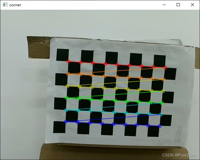
测试一下棋盘角点绘制
import cv2
img = cv2.imread('./calib/left/0.jpg')
img1 = cv2.cvtColor(img,cv2.COLOR_BGR2GRAY)
ret, corner = cv2.findChessboardCorners(img1, (9,6))
ret, corner = cv2.find4QuadCornerSubpix(img1, corner, (7,7))
cv2.drawChessboardCorners(img, (9,6), corner, ret)
cv2.imshow('corner', img)
cv2.waitKey(0)
接下来就获取矫正所需要的参数
import cv2, glob
import numpy as np
'''
获得标定所需参数
'''
# 定义棋盘格的大小
chessboard_size = (9, 6)
# 定义图像分辨率,根据自己相机的分辨率修改
imgsz = (640, 480)
# 定义棋盘格中每个格子的物理大小,自己用尺子量,单位为毫米(mm)
square_size = 24

# 定义棋盘格模板的点的坐标
objp = np.zeros((chessboard_size[0]*chessboard_size[1], 3), np.float32) #生成每个角点三维坐标,共有chessboard_size[0]*chessboard_size[1]个坐标,z轴置0不影响
objp[:, :2] = np.mgrid[0:chessboard_size[0], 0:chessboard_size[1]].T.reshape(-1, 2) * square_size #计算得到每个角点的x,y

# 读取所有棋盘格图像并提取角点
imgpoints_left, imgpoints_right = [], []  # 存储图像中的角点
objpoints = []  # 存储模板中的角点
images = glob.glob('./calibration/right/*.jpg')  # 所有棋盘格图像所在的目录
for fname in images:
    img = cv2.imread(fname)
    gray = cv2.cvtColor(img, cv2.COLOR_BGR2GRAY)
    ret, corners = cv2.findChessboardCorners(gray, chessboard_size, None) #计算corner
    ret, corners = cv2.find4QuadCornerSubpix(gray, corners, (7,7)) #提高角点检测的准确性和稳定性
    if ret == True:
        imgpoints_right.append(corners)
        objpoints.append(objp)

images = glob.glob('./calibration/left/*.jpg')  # 所有棋盘格图像所在的目录
for fname in images:
    img = cv2.imread(fname)
    gray = cv2.cvtColor(img, cv2.COLOR_BGR2GRAY)
    ret, corners = cv2.findChessboardCorners(gray, chessboard_size, None) #计算corner
    ret, corners = cv2.find4QuadCornerSubpix(gray, corners, (7,7)) #提高角点检测的准确性和稳定性
    if ret == True:
        imgpoints_left.append(corners)
'''
开始标定,获得参数
'''
# 标定相机,获得内参和畸变参数
ret, mtx_r, dist_r, rvecs_r, tvecs_r = cv2.calibrateCamera(objpoints, imgpoints_right, gray.shape[::-1], None, None)
ret, mtx_l, dist_l, rvecs_l, tvecs_l = cv2.calibrateCamera(objpoints, imgpoints_left, gray.shape[::-1], None, None)

# 指定迭代次数最大30或者误差小于0.001
term = (cv2.TERM_CRITERIA_EPS + cv2.TERM_CRITERIA_MAX_ITER, 30, 0.001)

# 进行双目相机标定,主要是获得R,T两个矩阵
rotation_matrix, translation_matrix = cv2.stereoCalibrate(
            objpoints, imgpoints_left, imgpoints_right,
            mtx_l, dist_l,
            mtx_r, dist_r,
            imgsz, flags=cv2.CALIB_FIX_INTRINSIC, criteria=term)[5:7]

# 获得矫正矩阵和投影矩阵,用于后续进行图像校正
rect_left, rect_right, \
proj_left, proj_right, \
dispartity, \
ROI_left, ROI_right = cv2.stereoRectify(
            mtx_l, dist_l,
            mtx_r, dist_r,
            imgsz, rotation_matrix, translation_matrix,
            flags=cv2.CALIB_ZERO_DISPARITY, alpha=-1)


'''
打印结果
'''
print('mtx_l = np.array({})'.format(np.array2string(mtx_l, separator=', ', formatter={'int': lambda x: f'{x: 3d}'},prefix='[', suffix=']')))
print('mtx_r = np.array({})'.format(np.array2string(mtx_r, separator=', ', formatter={'int': lambda x: f'{x: 3d}'},prefix='[', suffix=']')))
print('dist_l = np.array({})'.format(np.array2string(dist_l, separator=', ', formatter={'int': lambda x: f'{x: 3d}'},prefix='[', suffix=']')))
print('dist_r = np.array({})'.format(np.array2string(dist_r, separator=', ', formatter={'int': lambda x: f'{x: 3d}'},prefix='[', suffix=']')))
print('R = np.array({})'.format(np.array2string(rotation_matrix, separator=', ', formatter={'int': lambda x: f'{x: 3d}'},prefix='[', suffix=']')))
print('T = np.array({})'.format(np.array2string(translation_matrix, separator=', ', formatter={'int': lambda x: f'{x: 3d}'},prefix='[', suffix=']')))
print('rect_left = np.array({})'.format(np.array2string(rect_left, separator=', ', formatter={'int': lambda x: f'{x: 3d}'},prefix='[', suffix=']')))
print('rect_right = np.array({})'.format(np.array2string(rect_right, separator=', ', formatter={'int': lambda x: f'{x: 3d}'},prefix='[', suffix=']')))
print('proj_left = np.array({})'.format(np.array2string(proj_left, separator=', ', formatter={'int': lambda x: f'{x: 3d}'},prefix='[', suffix=']')))
print('proj_right = np.array({})'.format(np.array2string(proj_right, separator=', ', formatter={'int': lambda x: f'{x: 3d}'},prefix='[', suffix=']')))
print('dispartity = np.array({})'.format(np.array2string(dispartity, separator=', ', formatter={'int': lambda x: f'{x: 3d}'},prefix='[', suffix=']')))
# print('mtx_l = np.array({})'.format(mtx_l))
# print('mtx_r = np.array({})'.format(mtx_r))
# print('dist_l = np.array({})'.format(dist_l))
# print('dist_r = np.array({})'.format(dist_r))
# print('R = np.array({})'.format(rotation_matrix))
# print('T = np.array({})'.format(translation_matrix))
# print('rect_left = np.array({})'.format(rect_left))
# print('rect_right = np.array({})'.format(rect_right))
# print('proj_left = np.array({})'.format(proj_left))
# print('proj_right = np.array({})'.format(proj_right))
# print('dispartity = np.array({})'.format(dispartity))
print('ROI_left = np.array({})'.format(ROI_left))
print('ROI_right = np.array({})'.format(ROI_right))
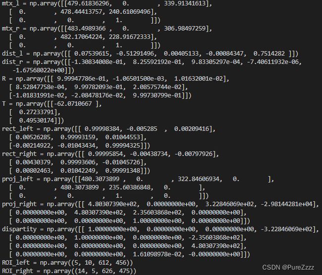
得到下面参数
可以直接复制用于图像矫正
测试
import cv2, glob, os
import numpy as np
def get_corners(imgs, corners):
    for img in imgs:
        # 9x12棋盘有8x11个角点
        ret, c = cv2.findChessboardCorners(img, (9,6))
        assert(ret)
        ret, c = cv2.find4QuadCornerSubpix(img, c, (7,7))
        assert(ret)
        corners.append(c)
mtx_l = np.array([[479.61836296,   0.,         339.91341613],
 [  0.,         478.44413757, 240.61069496],
 [  0.,           0.,           1.,        ]])
mtx_r = np.array([[483.4989366,    0.,         306.98497259],
 [  0.,         482.17064224, 228.91672333],
 [  0.,           0.,           1.        ]])
dist_l = np.array([[ 0.07539615, -0.51291496,  0.00405133, -0.00084347,  0.7514282 ]])
dist_r = np.array([[-1.30834008e-01,  8.25592192e-01,  9.83305297e-04, -7.40611932e-06,  -1.67568022e+00]])
R = np.array([[ 9.99947786e-01, -1.06501500e-03,  1.01632001e-02],
 [ 8.52847758e-04,  9.99782093e-01,  2.08575744e-02],
 [-1.01831991e-02, -2.08478176e-02,  9.99730799e-01]])
T = np.array([[-62.0710667 ],
 [  0.27233791],
 [  0.49530174]])
rect_left = np.array([[ 0.99998384, -0.005285,    0.00209416],
 [ 0.00526285,  0.99993159,  0.01044553],
 [-0.00214922, -0.01043434,  0.99994325]])
rect_right = np.array([[ 0.99995854, -0.00438734, -0.00797926],
 [ 0.00430379,  0.99993606, -0.01045726],
 [ 0.00802463,  0.01042249,  0.99991348]])
proj_left = np.array([[480.3073899,    0.,         322.84606934,   0.,        ],
 [  0.,         480.3073899,  235.60386848,   0.,        ],
 [  0.,           0.,           1.,           0.,        ]])
proj_right = np.array([[ 4.80307390e+02,  0.00000000e+00,  3.22846069e+02, -2.98144281e+04],
 [ 0.00000000e+00,  4.80307390e+02,  2.35603868e+02,  0.00000000e+00],
 [ 0.00000000e+00,  0.00000000e+00,  1.00000000e+00,  0.00000000e+00]])
dispartity = np.array([[ 1.00000000e+00,  0.00000000e+00,  0.00000000e+00, -3.22846069e+02],
 [ 0.00000000e+00,  1.00000000e+00,  0.00000000e+00, -2.35603868e+02],
 [ 0.00000000e+00,  0.00000000e+00,  0.00000000e+00,  4.80307390e+02],
 [ 0.00000000e+00,  0.00000000e+00,  1.61098978e-02, -0.00000000e+00]])
ROI_left = np.array((5, 10, 612, 456))
ROI_right = np.array((14, 5, 626, 475))
img_left = []
img_right = []
corners_left = []
corners_right = []
img_file = glob.glob('./calibration/*.jpg')
imgsize = (640, 480)

for img in img_file:
    frame = cv2.imread(img)
    frame = cv2.cvtColor(frame, cv2.COLOR_BGR2GRAY)
    l = frame[:,0:640]
    r = frame[:,640:]
    img_left.append(l)
    img_right.append(r)
print("获取角点", "left")
get_corners(img_left, corners_left)
print("获取角点", "right")
get_corners(img_right, corners_right)
for i in range(len(img_left)):
    l = img_left[i]
    r = img_right[i]
    # 计算双目校正的矩阵
    R1, R2, P1, P2, Q, validPixROI1, validPixROI2 = cv2.stereoRectify(mtx_l, dist_l, mtx_r, dist_r, imgsize, R, T)
    # 计算校正后的映射关系
    maplx , maply = cv2.initUndistortRectifyMap(mtx_l, dist_l, R1, P1, imgsize, cv2.CV_16SC2)
    maprx , mapry = cv2.initUndistortRectifyMap(mtx_r, dist_r, R2, P2, imgsize, cv2.CV_16SC2)
    # 映射新图像
    lr = cv2.remap(l, maplx, maply, cv2.INTER_LINEAR)
    rr = cv2.remap(r, maprx, mapry, cv2.INTER_LINEAR)
    all = np.hstack((lr,rr))
    # 变换之后和变换之前的角点坐标不一致,所以线不是正好经过角点,只是粗略估计,但偶尔能碰到离角点比较近的线,观察会比较明显
    cv2.line(all, (-1, int(corners_left[i][0][0][1])), (all.shape[1], int(corners_left[i][0][0][1])), (255), 1)
    # 可以看出左右图像y坐标对齐还是比较完美的,可以尝试着打印双目校正前的图片,很明显,左右y坐标是不对齐的
    cv2.imshow('a', all)
    c = cv2.waitKey()
    cv2.destroyAllWindows()
    if c == 27:
        break


print("end")
此段代码借鉴http://t.csdn.cn/uxwLA
参考链接:
Depther project - part 2: calibrate dual camera, parameters rectification - edgenoon.ai
http://t.csdn.cn/uxwLA
OpenCV: Create calibration pattern
opencv/pattern.png at 4.x · opencv/opencv · GitHub
Stereo Calibration for the Dual Camera Mezzanine - Blog - FPGA - element14 Community


