Real-Time Rendering——5.3 Implementing Shading Models 实现着色模型 5.3.1 Frequency of Evaluation 计算的频率
To be useful, these shading and lighting equations must of course be implemented in code. In this section we will go over some key considerations for designing and writing such implementations. We will also walk through a simple implementation example.
为了有用,这些阴影和照明方程当然必须用代码实现。在这一节中,我们将讨论设计和编写这种实现的一些关键考虑因素。我们还将浏览一个简单的实现示例。
When designing a shading implementation, the computations need to be divided according to their frequency of evaluation.
设计着色实现时,需要根据计算的频率来划分计算。
First, determine whether the result of a given computation is always constant over an entire draw call. In this case, the computation can be performed by the application, typically on the CPU, though a GPU compute shader could be used for especially costly computations. The results are passed to the graphics API via uniform shader inputs.
首先,确定给定计算的结果在整个drawcall中是否总是恒定的。在这种情况下,计算可以由应用程序执行,通常在CPU上执行,尽管GPU计算着色器可以用于特别昂贵的计算。结果通过统一着色器输入传递给图形API。
Even within this category, there is a broad range of possible frequencies of evaluation,starting from “once ever.” The simplest such case would be a constant subexpression in the shading equation, but this could apply to any computation based on rarely changing factors such as the hardware configuration and installation options.Such shading computations might be resolved when the shader is compiled, in which case there is no need to even set a uniform shader input. Alternatively, the computation might be performed in an offline precomputation pass, at installation time, or when the application is loaded.
即使在这一类别中,也有很大范围的可能的计算频率,从“曾经”开始。最简单的这种情况是着色方程中的常数子表达式,但是这可以应用于任何基于很少改变的因素的计算,例如硬件配置和安装选项。这种着色计算可能会在着色器编译时解决,在这种情况下,甚至不需要设置统一的着色器输入。或者,可以在安装时或加载应用程序时,在离线预计算过程中执行计算。
Another case is when the result of a shading computation changes over an application run, but so slowly that updating it every frame is not necessary. For example,lighting factors that depend on the time of day in a virtual game world. If the computation is costly, it may be worthwhile to amortize it over multiple frames.
另一种情况是,着色计算的结果在应用程序运行过程中发生变化,但变化非常缓慢,因此没有必要每帧都进行更新。例如,在虚拟游戏世界中依赖于一天中的时间的照明因素。如果计算成本很高,将它分摊到多个帧上可能是值得的。
Other cases include computations that are performed once per frame, such as concatenating the view and perspective matrices; or once per model, such as updating model lighting parameters that depend on location; or once per draw call, e.g., updating parameters for each material within a model. Grouping uniform shader inputs by frequency of evaluation is useful for application efficiency, and can also help GPU performance by minimizing constant updates.
其他情况包括每帧执行一次的计算,例如连接视图和透视矩阵;或者每个模型一次,例如更新依赖于位置的模型照明参数;或者每次绘图调用一次,例如,更新模型中每种材料的参数。按评估频率对统一着色器输入进行分组有助于提高应用效率,还可以通过最大限度地减少持续更新来提高GPU性能。
If the result of a shading computation changes within a draw call, it cannot be passed to the shader through a uniform shader input. Instead, it must be computed by one of the programmable shader stages described in Chapter 3 and, if needed, passed to other stages via varying shader inputs. In theory, shading computations can be performed on any of the programmable stages, each one corresponding to a different evaluation frequency:
如果着色计算的结果在绘制调用中发生变化,则不能通过统一着色器输入将其传递给着色器。相反,它必须由第3章中描述的一个可编程着色器阶段计算,如果需要,通过不同的着色器输入传递到其他阶段。理论上,着色计算可以在任何可编程阶段上执行,每个阶段对应不同的计算频率:
• Vertex shader—Evaluation per pre-tessellation vertex.
• Hull shader—Evaluation per surface patch.
• Domain shader—Evaluation per post-tessellation vertex.
• Geometry shader—Evaluation per primitive.
• Pixel shader—Evaluation per pixel.
顶点着色器—每个曲面细分前顶点的评估。
外壳着色器——每个表面片段的评估。
域着色器—每个曲面细分后顶点的评估。
几何着色器—每个图元的评估。
像素着色器—每像素评估。
In practice most shading computations are performed per pixel. While these are typically implemented in the pixel shader, compute shader implementations are increasingly common;several examples will be discussed in Chapter 20. The other stages are primarily used for geometric operations such as transformation and deformation.To understand why this is the case, we will compare the results of per-vertex and perpixel shading evaluations. In older texts, these are sometimes referred to as Gouraud shading and Phong shading, respectively, though those terms are not often used today. This comparison uses a shading model somewhat similar to the one in Equation 5.1, but modified to work with multiple light sources. The full model will be given a bit later, when we cover an example implementation in detail.
实际上,大多数着色计算都是按像素进行的。虽然这些通常在像素着色器中实现,但计算着色器的实现越来越常见;几个例子将在第20章讨论。其他阶段主要用于几何操作,如变换和变形。为了理解为什么会这样,我们将比较逐顶点和逐像素着色评估的结果。在较老的文本中,这些有时分别被称为Gouraud着色和Phong着色,尽管这些术语今天不常使用。这种比较使用的阴影模型有点类似于等式5.1中的模型,但进行了修改,以适用于多个光源。稍后,当我们详细介绍一个示例实现时,将给出完整的模型。
Figure 5.9 shows the results of per-pixel and per-vertex shading on models with a wide range of vertex densities. For the dragon, an extremely dense mesh, the difference between the two is small. But on the teapot, vertex shading evaluation causes visible errors such as angularly shaped highlights, and on the two-triangle plane the vertexshaded version is clearly incorrect.
图5.9显示了具有各种顶点密度的模型上的每像素和每顶点着色的结果。对于龙来说,一个极其密集的网,两者之间的差别很小。但是在茶壶上,顶点着色评估会导致可见的错误,例如成角度形状的高光,并且在两个三角形平面上,顶点着色版本显然是不正确的。
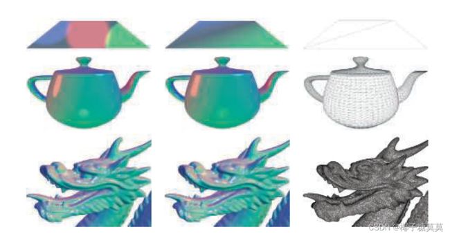
Figure 5.9. A comparison of per-pixel and per-vertex evaluations for the example shading model from Equation 5.19, shown on three models of varying vertex density. The left column shows the results of per-pixel evaluation, the middle column shows per-vertex evaluation, and the right column presents wireframe renderings of each model to show vertex density. (Chinese Dragon mesh from Computer Graphics Archive [1172], original model from Stanford 3D Scanning Repository.)
图5.9。公式5.19中的示例着色模型的每像素和每顶点评估的比较,显示在三个不同顶点密度的模型上。左栏显示每像素评估的结果,中间栏显示每顶点评估,右栏显示每个模型的线框渲染,以显示顶点密度。(中国龙网格来自计算机图形档案[1172],原始模型来自斯坦福3D扫描库。)
The cause of these errors is that parts of the shading equation, the highlight in particular, have values that vary nonlinearly over the mesh surface. This makes them a poor fit for the vertex shader, the results of which are interpolated linearly over the triangle before being fed to the pixel shader.
这些错误的原因是着色方程的部分,特别是高光,具有在网格表面上非线性变化的值。这使得它们不适合顶点着色器,顶点着色器的结果在馈送到像素着色器之前在三角形上线性插值。
In principle, it would be possible to compute only the specular highlight part of the shading model in the pixel shader, and calculate the rest in the vertex shader. This would likely not result in visual artifacts and in theory would save some computation.In practice, this kind of hybrid implementation is often not optimal. The linearly varying parts of the shading model tend to be the least computationally costly, and splitting up the shading computation in this way tends to add enough overhead, such as duplicated computations and additional varying inputs, to outweigh any benefit.
原则上,可以在像素着色器中仅计算着色模型的镜面高光部分,而在顶点着色器中计算其余部分。这可能不会导致视觉伪像,并且理论上将节省一些计算。在实践中,这种混合实现通常不是最佳的。着色模型的线性变化部分往往是计算成本最低的,并且以这种方式分割着色计算往往会增加足够的开销,例如重复的计算和额外的变化输入,从而超过任何好处。
As we mentioned earlier, in most implementations the vertex shader is responsible for non-shading operations such as geometry transformation and deformation. The resulting geometric surface properties, transformed into the appropriate coordinate system, are written out by the vertex shader, linearly interpolated over the triangle,and passed into the pixel shader as varying shader inputs. These properties typically include the position of the surface, the surface normal, and optionally surface tangent vectors, if needed for normal mapping.
正如我们前面提到的,在大多数实现中,顶点着色器负责非着色操作,如几何变换和变形。最终的几何表面属性被转换到适当的坐标系中,由顶点着色器写出,在三角形上线性插值,并作为可变着色器输入传递到像素着色器中。这些属性通常包括表面的位置、表面法线和可选的表面切向量(如果法线贴图需要)。
Note that even if the vertex shader always generates unit-length surface normals,interpolation can change their length. See the left side of Figure 5.10. For this reason the normals need to be renormalized (scaled to length 1) in the pixel shader. However,the length of the normals generated by the vertex shader still matters. If the normal length varies significantly between vertices, e.g., as a side effect of vertex blending,this will skew the interpolation. This can be seen in the right side of Figure 5.10. Due to these two effects, implementations often normalize interpolated vectors before and after interpolation, i.e., in both the vertex and pixel shaders.
注意,即使顶点着色器总是生成单位长度的表面法线,插值也可以改变它们的长度。参见图5.10的左侧。出于这个原因,法线需要在像素着色器中重新规格化(缩放到长度1)。然而,由顶点着色器生成的法线的长度仍然很重要。如果法线长度在顶点之间变化很大,例如,作为顶点混合的副作用,这将扭曲插值。这可以在图5.10的右侧看到。由于这两种影响,实现通常在插值之前和之后,即在顶点和像素着色器中,都对插值向量进行归一化。
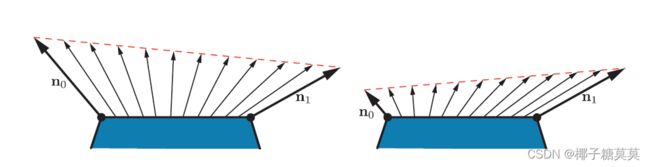
Figure 5.10. On the left, we see that linear interpolation of unit normals across a surface results in interpolated vectors with lengths less than one. On the right, we see that linear interpolation of normals with significantly different lengths results in interpolated directions that are skewed toward the longer of the two normals.
图5.10。在左边,我们看到单位法线在一个表面上的线性插值导致长度小于1的插值向量。在右边,我们看到长度明显不同的法线的线性插值导致插值方向偏向两条法线中较长的一条。
Unlike the surface normals, vectors that point toward specific locations, such as the view vector and the light vector for punctual lights, are typically not interpolated.Instead, the interpolated surface position is used to compute these vectors in the pixel shader. Other than the normalization, which as we have seen needs to be performed in the pixel shader in any case,each of these vectors is computed with a vector subtraction, which is quick.If for some reason it is necessary to interpolate these vectors, do not normalize them beforehand. This will yield incorrect results, as shown in Figure 5.11.
与表面法线不同,指向特定位置的向量(如点光源的视图向量和灯光向量)通常不会进行插值。相反,插值表面位置用于在像素着色器中计算这些向量。除了归一化(正如我们所看到的,在任何情况下都需要在像素着色器中执行)之外,这些向量中的每一个都是通过向量减法来计算的,这很快。如果由于某种原因,有必要对这些向量进行插值,不要预先对它们进行归一化。这将产生不正确的结果,如图5.11所示。
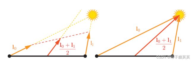
Figure 5.11. Interpolation between two light vectors. On the left, normalizing them before interpolation causes the direction to be incorrect after interpolation. On the right, interpolating the non-normalized vectors yields correct results.
图5.11。两个光矢量之间的插值。在左侧,在插值前对它们进行归一化会导致插值后方向不正确。在右边,内插非标准化向量产生正确的结果。
Earlier we mentioned that the vertex shader transforms the surface geometry into “the appropriate coordinate system.” The camera and light positions, passed to the pixel shader through uniform variables, are typically transformed by the application into the same coordinate system. This minimizes work done by the pixel shader to bring all the shading model vectors into the same coordinate space. But which coordinate system is the “appropriate” one? Possibilities include the global world space as well as the local coordinate system of the camera or, more rarely, that of the currently rendered model. The choice is typically made for the rendering system as a whole,based on systemic considerations such as performance, flexibility, and simplicity. For example, if rendered scenes are expected to include huge numbers of lights, world space might be chosen to avoid transforming the light positions. Alternately, camera space might be preferred, to better optimize pixel shader operations relating to the view vector and to possibly improve precision (Section 16.6).
前面我们提到过顶点着色器将表面几何体转换为“适当的坐标系”通过统一变量传递给像素着色器的相机和灯光位置通常由应用程序转换到相同的坐标系中。这最大限度地减少了像素着色器将所有着色模型向量带入同一坐标空间所做的工作。但是哪个坐标系是“合适的”坐标系呢?可能性包括全局世界空间以及相机的局部坐标系,或者更罕见的是,当前渲染模型的坐标系。这种选择通常是基于诸如性能、灵活性和简单性之类的系统考虑,作为一个整体为呈现系统做出的。例如,如果渲染的场景预计包括大量的灯光,则可以选择世界空间来避免变换灯光位置。或者,相机空间可能是首选,以更好地优化与视图向量相关的像素着色器操作,并可能提高精度(第16.6节)。
Although most shader implementations, including the example implementation we are about to discuss, follow the general outline described above, there are certainly exceptions. For example, some applications choose the faceted appearance of perprimitive shading evaluation for stylistic reasons. This style is often referred to as flat shading. Two examples are shown in Figure 5.12.
虽然大多数着色器实现,包括我们将要讨论的示例实现,都遵循上述的一般概述,但当然也有例外。例如,出于风格原因,一些应用程序选择正面着色评估的多面外观。这种风格通常被称为平面阴影。两个例子如图5.12所示。
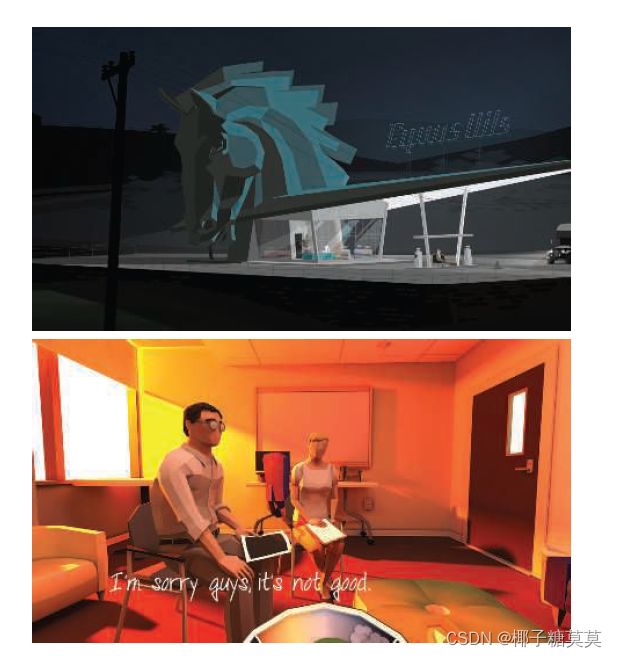
Figure 5.12. Two games that use flat shading as a stylistic choice: Kentucky Route Zero, top, and That Dragon, Cancer, bottom. (Upper image courtesy of Cardboard Computer, lower courtesy of Numinous Games.)
图5.12。两个游戏使用平面阴影作为风格选择:Kentucky Route Zero, top, and That Dragon, Cancer, bottom.(上图由Cardboard Computer提供,下图由Numinous Games提供。)
In principle, flat shading could be performed in the geometry shader, but recent implementations typically use the vertex shader. This is done by associating each primitive’s properties with its first vertex and disabling vertex value interpolation.Disabling interpolation (which can be done for each vertex value separately) causes the value from the first vertex to be passed to all pixels in the primitive.
原则上,平面着色可以在几何着色器中执行,但最近的实现通常使用顶点着色器。这是通过将每个图元的属性与其第一个顶点相关联并禁用顶点值插值来实现的。禁用插值(可以对每个顶点值分别执行)会导致第一个顶点的值传递给图元中的所有像素。