RK3568-ANDROID11-5G-RM500Q-PCIE
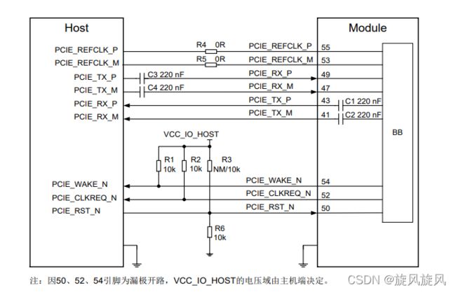
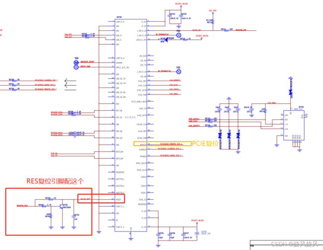
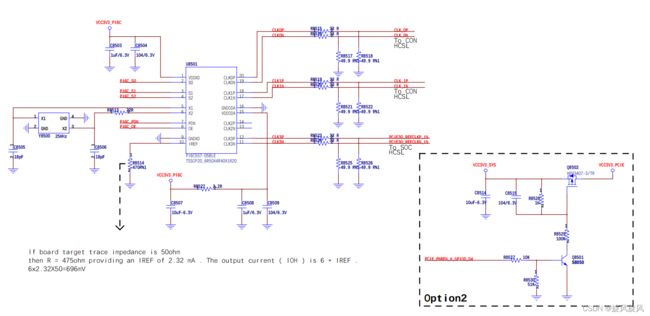
实际原理图
一、先配置硬件接线
	vcc3v3_pcie: gpio-regulator {
		compatible = "regulator-fixed";
		regulator-name = "vcc3v3_pcie";
		regulator-min-microvolt = <3300000>;
		regulator-max-microvolt = <3300000>;
		enable-active-high;
		gpio = <&gpio0 RK_PD4 GPIO_ACTIVE_LOW>;
		startup-delay-us = <5000>;
		vin-supply = <&dc_12v>;
		regulator-always-on;
		regulator-boot-on;
	};
然后时钟信号正常
然后测到电源3.7V 和使能3.3V供电
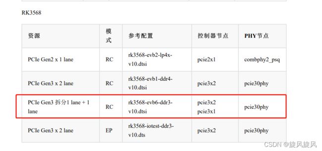
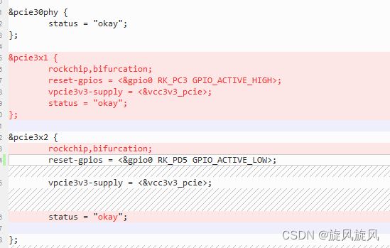
然后根据RK文档配置PCIE功能
&pcie30phy {
	status = "okay";
};

&pcie3x1 {
	rockchip,bifurcation;
	reset-gpios = <&gpio0 RK_PC3 GPIO_ACTIVE_HIGH>;
	vpcie3v3-supply = <&vcc3v3_pcie>;
	status = "okay";
};

&pcie3x2 {
	rockchip,bifurcation;
	reset-gpios = <&gpio0 RK_PD5 GPIO_ACTIVE_LOW>;
	vpcie3v3-supply = <&vcc3v3_pcie>;
	status = "okay";

};
配置完成DTS
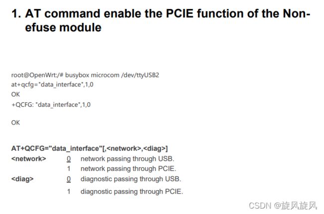
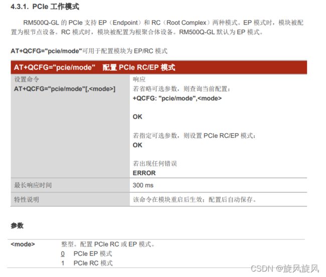
二、配置5G模块模式
//我用的是以下模式

at+qcfg="USBNET",0
at+qcfg="data_interface",1,0
AT+QCFG="pcie/mode",1
三、驱动移植,根据Quectel_Linux_PCIE_MHI_Driver_V1.3.1.zip
1. porting pcie_mhi driver as next

$ git diff drivers/Makefile
diff --git a/drivers/Makefile b/drivers/Makefile
index 77fbc52..e45837e 100644
--- a/drivers/Makefile
+++ b/drivers/Makefile
@@ -184,3 +184,4 @@ obj-$(CONFIG_FPGA)          += fpga/
 obj-$(CONFIG_FSI)              += fsi/
 obj-$(CONFIG_TEE)              += tee/
 obj-$(CONFIG_MULTIPLEXER)      += mux/
+obj-y          += pcie_mhi/

$ tree drivers/pcie_mhi/ -L 1
drivers/pcie_mhi/
 controllers
 core
 devices
 Makefile
四、修改驱动
4. IPQ PCIE 识别代码流程
4.1 IPQ 拉低 PCIE_RESET
drivers/pci/host/pcie-qcom.c
static void qcom_ep_reset_assert(struct qcom_pcie *pcie)
{
 //gpiod_set_value(pcie->reset, 1); //carl.yin delete this, will cause x55 link fail, i donot know why
 usleep_range(PERST_DELAY_US, PERST_DELAY_US + 500);
}
4.2 IPQ 拉高 PCIE_RESET
drivers/pci/host/pcie-qcom.c
static void qcom_ep_reset_deassert(struct qcom_pcie *pcie)
{
 gpiod_set_value(pcie->reset, 0);
 usleep_range(PERST_DELAY_US, PERST_DELAY_US + 500);
}
4.3 IPQ 开始PCIE识别, 默认识别10次,间隔100ms. 如果在这段时间内,SDX55的PCIE 没有READY,
会导致识别不成功, 可适当加大识别次数
drivers/pci/host/pcie-designware.c
int dw_pcie_wait_for_link(struct pcie_port *pp)


{
 int retries;
 /* check if the link is up or not */
 for (retries = 0; retries < LINK_WAIT_MAX_RETRIES; retries++) {
 if (dw_pcie_link_up(pp)) {
//如果识别成功,会打印如下代码的 LOG
 dev_info(pp->dev, "link up. retries %d\n", retries);
 return 0;
 }
 usleep_range(LINK_WAIT_USLEEP_MIN, LINK_WAIT_USLEEP_MAX);
 if (strstr(dev_name(pp->dev), "20000000")) {
 //usleep_range(LINK_WAIT_USLEEP_MIN, LINK_WAIT_USLEEP_MAX);
 //usleep_range(LINK_WAIT_USLEEP_MIN, LINK_WAIT_USLEEP_MAX);
 }
 }
//如果识别不成功,会打印如下代码的 LOG
 dev_err(pp->dev, "phy link never came up. retries %d\n", retries);
 return -ETIMEDOUT;
}
五、可能需要配置4G移植好的RILD库
RK3568-ANDROID11-4G-EC20-(详细步骤)_longmin96的博客-CSDN博客
六、看到图标
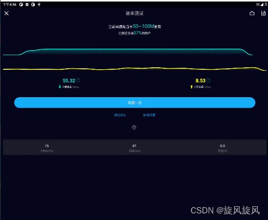
七、测速看一下网络
八、关电插上M.2开机,完成
九、遇到问题
[    0.555786] phy phy-fe8c0000.phy.8: phy init failed --> -110
[    0.555802] rk-pcie 3c0400000.pcie: fail to init phy, err -110
[    0.555816] rk-pcie 3c0400000.pcie: phy init failed
解决:打开晶振芯片电源GPIO,看到晶振起振
