MGER-OSPF的LSA-OSPF的优化 综合实验报告
题目: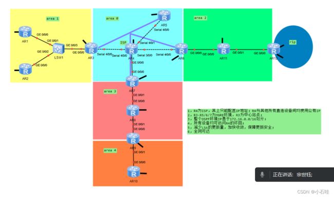
步骤一:拓扑设计,地址规划
地址规划:
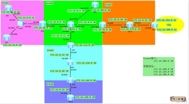
有题意知:整个OSPF环境基于172.16.0.0/16划分。则据提意划分出子网掩码长度为20的,十六个网段,如下:
骨干链路:使用172.16.0.0 20网段172.16.0.0 21网段划分为:
172.16.0.0 30
172.16.0.4 30
172.16.0.8 30
172.16.0.12 30
172.16.0.16 30
172.16.0.20 30
172.16.0.24 30
172.16.0.28 30
172.16.0.32 30
area1区域:172.16.8.0 21
环回接口:
172.16.16.0 20
172.16.32.0 20
172.16.48.0 20
172.16.64.0 20
172.16.80.0 20
172.16.96.0 20
172.16.112.0 20
172.16.128.0 20
172.16.144.0 20
172.16.160.0 20
172.16.176.0 20
172.16.192.0 20划分为:172.16.192.0 21 和 172.16.200.0 21在R12上进行使用
Tunnel接口:
172.16.208.0 20
保留地址:
172.16.208.0 20
172.16.224.0 20
172.16.240.0 20
拓扑设计:
步骤三:配置IP地址
由于IP地址过多则将其拼接在一起写
[R1-GigabitEthernet0/0/0]ip add 172.16.8.1 21
[R1-LoopBack0]ip add 172.16.16.1 20

[R2-GigabitEthernet0/0/0]ip add 172.16.8.2 21
[R2-LoopBack0]ip add 172.16.32.1  20

[R3-GigabitEthernet0/0/0]ip add 172.16.8.3 21
[R3-LoopBack0]ip add 172.16.48.1 20
[R3-Serial4/0/0]ip add 172.16.0.1 30

[R4-LoopBack0]ip add 172.16.64.1 20
[R4-Serial4/0/0]ip add 172.16.0.2 30
[R4-Serial4/0/1]ip add 172.16.0.5 30
[R4-Serial3/0/0]ip add 172.16.0.9 30
[R4-GigabitEthernet0/0/0]ip add 172.16.0.13 30

[R5-Serial4/0/0]ip add 172.16.0.6 30
[R5-LoopBack0]ip add 172.16.80.1 20

[R6-GigabitEthernet0/0/0]ip add 172.16.0.29 30
[R6-LoopBack0]ip add 172.16.96.1 20
[R6-Serial4/0/0]ip add 172.16.0.10 30

[R7-GigabitEthernet0/0/0]ip add 172.16.0.14 30
[R7-GigabitEthernet0/0/1]ip add 172.16.0.17 30
[R7-LoopBack0]ip add 172.16.112.1 20

[R8-GigabitEthernet0/0/0]ip add 172.16.0.18 30
[R8-GigabitEthernet0/0/1]ip add 172.16.0.21 30
[R8-LoopBack0]ip add 172.16.128.1 20

[R9-GigabitEthernet0/0/0]ip add 172.16.0.22 30
[R9-GigabitEthernet0/0/1]ip add 172.16.0.25 30
[R9-LoopBack0]ip add 172.16.144.1 20

[R10-GigabitEthernet0/0/0]ip add 172.16.0.26 30
[R10-LoopBack0]ip add 172.16.160.1 20


[R11-GigabitEthernet0/0/0]ip add 172.16.0.30 30
[R11-GigabitEthernet0/0/1]ip add 172.16.0.33 30
[R11-LoopBack0]ip add 172.16.176.1 20

[R12-GigabitEthernet0/0/0]ip add 172.16.0.34 30
[R12-LoopBack0]ip add 172.16.192.1 21
[R12-LoopBack1]ip add 172.16.200.1 21
步骤四:为MGER做铺垫,配置缺省路由:
[R1]ip route-static 0.0.0.0 0 172.16.8.3

[R2]ip route-static 0.0.0.0 0 172.16.8.3

[R3]ip route-static 0.0.0.0 0 172.16.0.2

[R5]ip route-static 0.0.0.0 0 172.16.0.5

[R6]ip route-static 0.0.0.0 0 172.16.0.9

[R7]ip route-static 0.0.0.0 0 172.16.0.13
步骤五:NAT 配置
由题意知,R4为ISP因此给R3 R5 R6 R6 均配置NAT,方法如下:
[R3]acl 2000

[R3-acl-basic-2000]rule  1 permit source any
[R3-acl-basic-2000]q
[R3-Serial4/0/0]nat outbound 2000
     # 只有R7为[R7-GigabitEthernet0/0/0]nat outbound 2000
步骤六:构建MGRE环境
R3 R5 R6 R7处于MGER环境,且R3为中心站点
Tunnel接口:172.16.208.0 20
配置R3(中心站点的构建)
[R3]int t 0/0/0                            # 创建隧道口
[R3-Tunnel0/0/0]ip add 172.16.208.1 20     # 为隧道接口配置IP地址
[R3-Tunnel0/0/0]tunnel-protocol gre p2mp   # 修改接口模式为多点GRE模式
[R3-Tunnel0/0/0]source 172.16.0.1          # 定义封装源
[R3-Tunnel0/0/0]nhrp network-id 100        # 创建域ID
分支站点构建
R5
[R5]int t 0/00/0
[R5-Tunnel0/0/0]ip add 172.16.208.2 20
[R5-Tunnel0/0/0]tunnel-protocol gre p2mp
[R5-Tunnel0/0/0]nhrp entry 172.16.208.1 172.16.0.1 register
[R5-Tunnel0/0/0]nhrp network-id 100
R6
[R6]int t 0/0/0
[R6-Tunnel0/0/0]ip add 172.16.208.3 20
[R6-Tunnel0/0/0]tunnel-protocol gre  p2mp
[R6-Tunnel0/0/0]nhrp entry 172.16.208.1 172.16.0.1 register
[R6-Tunnel0/0/0]nhrp network-id 100
R7
[R7]int t 0/00/0
[R7-Tunnel0/0/0]ip add 172.16.208.4 20
[R7-Tunnel0/0/0]tunnel-protocol gre p2mp
[R7-Tunnel0/0/0]source G0/00/0
[R7-Tunnel0/0/0]nhrp entry 172.16.208.1 172.16.0.1 register
[R7-Tunnel0/0/0]nhrp network-id 100
步骤七:OSPF及RIP配置路由
1.配置路由
R1
ospf 1 router-id 1.1.1.1
 area 0.0.0.1
  network 172.16.8.0 0.0.7.255
  network 172.16.16.0 0.0.15.255
R2
ospf 1 router-id 2.2.2.2
 area 0.0.0.1
  network 172.16.8.0 0.0.7.255
  network 172.16.32.0 0.0.15.255
R3
ospf 1 router-id 3.3.3.3
 area 0.0.0.0
  network 172.16.208.0 0.0.15.255
 area 0.0.0.1
  network 172.16.8.0 0.0.7.255
  network 172.16.48.0 0.0.15.255
R5
ospf 1 router-id 5.5.5.5
 area 0.0.0.0
  network 172.16.80.0 0.0.15.255
  network 172.16.208.0 0.0.15.255
R6
ospf 1 router-id 6.6.6.6
 area 0.0.0.0
  network 172.16.208.0 0.0.15.255
 area 0.0.0.2
  network 172.16.0.28 0.0.0.3
  network 172.16.96.0 0.0.15.255
R7
ospf 1 router-id 7.7.7.7
 area 0.0.0.0
  network 172.16.208.0 0.0.15.255
 area 0.0.0.3
  network 172.16.0.16 0.0.0.3
  network 172.16.112.0 0.0.15.255
R8
ospf 1 router-id 8.8.8.8
 area 0.0.0.3
  network 172.16.0.16 0.0.0.3
  network 172.16.0.20 0.0.0.3
  network 172.16.128.0 0.0.15.255
R9
ospf 1 router-id 9.9.9.9
 area 0.0.0.3
  network 172.16.0.20 0.0.0.3
 area 0.0.0.4
  network 172.16.0.24 0.0.0.3
  network 172.16.144.0 0.0.15.255
R10
ospf 1 router-id 10.10.10.10
 area 0.0.0.4
  network 172.16.0.24 0.0.0.3
  network 172.16.160.0 0.0.15.255
R11
ospf 1 router-id 11.11.11.11
 import-route rip 1
 area 0.0.0.2
  network 172.16.0.28 0.0.0.3
  network 172.16.0.32 0.0.0.3
  network 172.16.176.0 0.0.15.255
E12
ospf 1 router-id 12.12.12.12
 area 0.0.0.2
  network 172.16.0.32 0.0.0.3
#
rip 1
 version 2
 network 172.16.0.0
 import-route ospf 1
2.修改接口网络类型
查看接口网络类型方法:display ospf interface Tunnel 0/0/0
修改接口网络类型方法:
进入对应接口(隧道接口)后 ospf network-type ~类型~
3.打开伪广播
进入对应接口(中心站点隧道)后 nhrp entry multicast dynamic
步骤八:检测MGRE
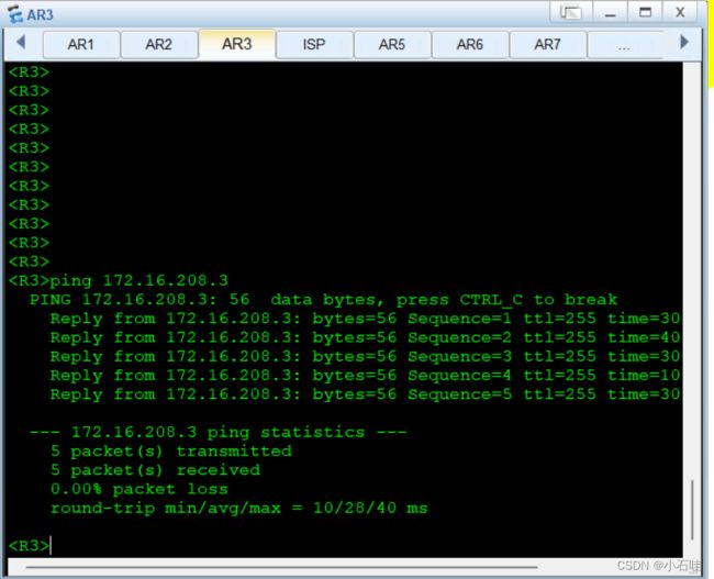
检测:
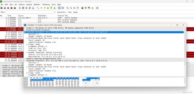
使用R3 R5 R6 R7处于MGER环境中的任何俩台设备去互ping。
与此同时,去抓包。
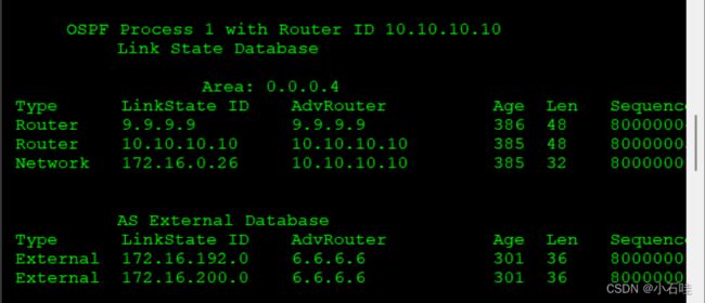
步骤九:做特殊区域减少LSA更新量
设置STUB
由于R9R10不连接ASBR因此可以作为STUB
[R9-ospf-1-area-0.0.0.4]stub
[R9-ospf-1-area-0.0.0.4]stub no-summary

[R10-ospf-1-area-0.0.0.4]stub
[R10-ospf-1-area-0.0.0.4]stub no-summary
做之前:
做之后:
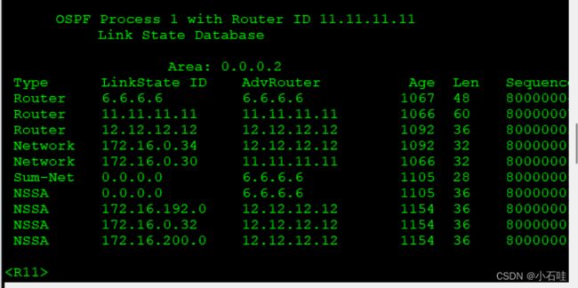
设置NSSA
由于R11R12连接ASBR因此可以作为NSSA
[R6-ospf-1-area-0.0.0.2]nssa
[R6-ospf-1-area-0.0.0.2]nssa no-summary

[R11-ospf-1-area-0.0.0.2]nssa
[R11-ospf-1-area-0.0.0.2]nssa no-summary


[R12-ospf-1-area-0.0.0.2]nssa
[R12-ospf-1-area-0.0.0.2]nssa no-summary
给R3 配置缺省以达到全网都可以访问R4
[R3-ospf-1]default-route-advertise always 