SRV6 BE
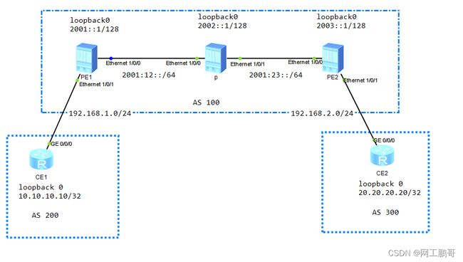
实验目的:通过SRV6 BE实现CE之间的ipv4网络互访
步骤1:配置ISP网络设备的ipv6地址
步骤2:配置ISP网络的IGP协议(ISIS ipv6)设备配置前先在每台设备上面 undo dcn
PE1:
isis 1

 cost-style wide

 network-entity 49.0001.0000.0000.0001.00

ipv6 enable topology ipv6


interface Ethernet1/0/0

 undo shutdown

 ipv6 enable

 ipv6 address 2001:12::1/64

 isis ipv6 enable 1


interface LoopBack0

 ipv6 enable

 ipv6 address 2001::1/128

 isis ipv6 enable 1
PE2:
isis 1

 cost-style wide

 network-entity 49.0001.0000.0000.0002.00

 ipv6 enable topology ipv6


interface LoopBack0

 ipv6 enable

 ipv6 address 2002::1/128

 isis ipv6 enable 1


interface Ethernet1/0/0

ipv6 enable

 ipv6 address 2001:12::2/64

 isis ipv6 enable 1


interface Ethernet1/0/1

ipv6 enable

 ipv6 address 2001:23::2/64

 isis ipv6 enable 1
PE3:
interface Ethernet1/0/0

 undo shutdown

 ipv6 enable

 ipv6 address 2001:23::3/64


interface LoopBack0

 ipv6 enable

 ipv6 address 2003::1/64

 isis ipv6 enable 1


isis 1

 cost-style wide

 network-entity 49.0001.0000.0000.0003.00

 #

 ipv6 enable topology ipv6
步骤3:在PE设备上配置实例,PE设备与CE设备建立BGP邻居关系
PE1:
ip -instance 1 //创建实例

 ipv4-family

  route-distinguisher 1:1

  -target 1:1 export-extcommunity

  -target 1:1 import-extcommunity


interface Ethernet1/0/1 //将接口绑定实例

 ip binding -instance 1

 ip address 192.168.1.1 255.255.255.0


bgp 100 //配置与CE建立BGP邻居

ipv4-family -instance 1

  peer 192.168.1.2 as-number 200
PE2:
ip -instance 1

 ipv4-family

  route-distinguisher 1:1

  -target 1:1 export-extcommunity

  -target 1:1 import-extcommunity

interface Ethernet1/0/1

ip binding -instance 1

 ip address 192.168.2.1 255.255.255.0


bgp 100//配置与CE建立BGP邻居

ipv4-family -instance 1

  peer 192.168.2.2 as-number 300
CE1:
bgp 200

peer 192.168.1.1 as-number 100

network 10.10.10.10 255.255.255.255
CE2
bgp 300

peer 192.168.2.1 as-number 100

network 20.20.20.20 255.255.255.255
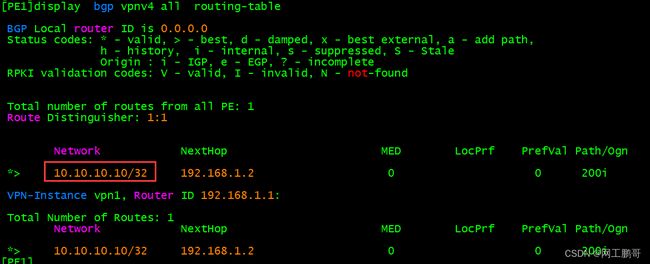
配置完后PE上可以看到CE设备v4的路由
步骤4:配置PE1和PE2的v4邻居关系
PE1:
bgp 100

 router-id 1.1.1.1//一定要配置router id ,bgp4+无法自动生成router id

 peer 2003::1 as-number 100

 peer 2003::1 connect-interface LoopBack0

ipv4-family v4

  peer 2003::1 enable
PE2:
bgp 100

router-id 2.2.2.2

 peer 2001::1 as-number 100

 peer 2001::1 connect-interface LoopBack0

ipv4-family v4

  peer 2001::1 enable
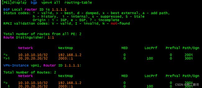
查看PE1的v4邻居以及路由表
可以看到对端的v4以及学习到了,但是没有放入实例的路由表中没有被优选。
没被优选的原因是由于隧道不可达,接下来配置srv6的隧道,用于传递CE之间的数据
步骤5:配置SRV6 BE
(1)开启SRv6功能,并且配置SRv6的locator
PE1:
segment-routing ipv6 //使能srv6功能

 encapsulation source-address 2001::1//配置SRv6 VPN封装的源地址,一般使用bgp的更新源地址

 locator pe1 ipv6-prefix 2001:ABCD:: 64 static 32 //配置静态locator的前缀为2001:ABCD::/64 取值范围为后32位
PE2:
segment-routing ipv6

 encapsulation source-address 2003::1

 locator PE2 ipv6-prefix 2003:ABCD:: 64 static 32
查看配置结果
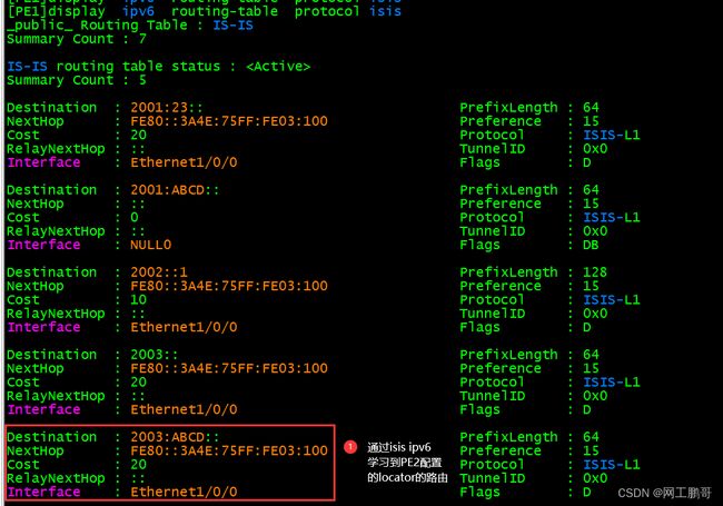
(2)配置isis的srv6功能
PE1
isis 1

segment-routing ipv6 locator PE1 //使能isis的SRv6功能,利用isis通告locator的前缀路由
PE2
isis 1

segment-routing ipv6 locator PE2
(3)配置BGP的srv6功能
PE1:
Bgp 100

ipv4-family v4

peer 2003::1 prefix-sid //向对端pe通告路由的时候携带sid属性

ipv4-family -instance 1

  segment-routing ipv6 locator PE1//使能VPN私网路由携带SID属性

  segment-routing ipv6 best-effort //使能根据路由携带的SID属性进行私网路由迭代
PE2:
Bgp 100

ipv4-family v4

peer 2001::1 prefix-sid

ipv4-family -instance 1

segment-routing ipv6 locator PE2

segment-routing ipv6 best-effort
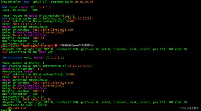
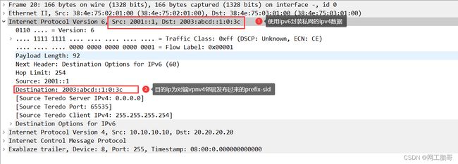
本地生成的sid,类似mpls中的私网标签,用于决定收到此dip时,发往哪一个实例
在CE1 ping CE2
ping -a 10.10.10.10 20.20.20.20

  PING 20.20.20.20: 56  data bytes, press CTRL_C to break

    Reply from 20.20.20.20: bytes=56 Sequence=1 ttl=253 time=40 ms

    Reply from 20.20.20.20: bytes=56 Sequence=2 ttl=253 time=30 ms

    Reply from 20.20.20.20: bytes=56 Sequence=3 ttl=253 time=40 ms

    Reply from 20.20.20.20: bytes=56 Sequence=4 ttl=253 time=30 ms

Reply from 20.20.20.20: bytes=56 Sequence=5 ttl=253 time=30 ms 